NGIU08 - Switch Tripp Lite - Free user manual and instructions
Find the device manual for free NGIU08 Tripp Lite in PDF.
| Technical Features | 8-port network switch, 10/100/1000 Mbps, unmanaged |
|---|---|
| Usage | Ideal for small businesses or home networks to connect multiple devices. |
| Maintenance and Repair | No maintenance required, robust design for extended use. |
| Security | Built-in surge and short circuit protection. |
| General Information | Compatible with Ethernet standards, plug-and-play installation, no configuration needed. |
Frequently Asked Questions - NGIU08 Tripp Lite
User questions about NGIU08 Tripp Lite
0 question about this device. Answer the ones you know or ask your own.
Ask a new question about this device
Download the instructions for your Switch in PDF format for free! Find your manual NGIU08 - Tripp Lite and take your electronic device back in hand. On this page are published all the documents necessary for the use of your device. NGIU08 by Tripp Lite.
USER MANUAL NGIU08 Tripp Lite
Unmanaged Industrial Gigabit Ethernet Switches, Plug and Play, Mountable
Models: NGI-U05, NGI-U16
Espanol 17 • Français 33 • Pycckn 49 • Deutsch 65
WARRANTY REGISTRATION
Register your product today and be automatically entered to win an ISOBAR®
surge protector in our monthly drawing!
triplite.com/warranty

1111 W. 35th Street, Chicago, IL 60609 USA · tripplite.com/support
Copyright © 2022 Tripp Lite. All rights reserved.
Package Contents
- NGI-U05 or NGI-U16 Gigabit Ethernet Switch
- Owner's Manual
Product Features
- 5 (NGI-U05) or 16 (NGI-U16) auto-negotiable 10/100/1000 Mbps RJ45 ports
Supports auto MDI/MDI-X crossover function
Supports operating temperature range of -40^ to 75^ (-40°F to 167°F) - Easy-to-read LEDs indicate connection and activity status for each port
-
Meets the following IEEE standards:
-
IEEE 802.3 10Base-T
- IEEE 802.3u 100Base-T
- IEEE 802.3ab 1000Base-T
- IEEE 802.3 Auto Negotiation
- IEEE 802.3x Flow Control
Supports MAC address auto-learning and auto-aging
- Preinstalled durable rail clip mounts firmly to any standard 35 mm DIN rail*
- Simple plug-and-play installation and operation with no configuration required
*Note: Only NGI-U05 is both DIN and wall mountable
Optional Accessories
N001-Series Cat5e 350 MHz Snagless UTP Cables
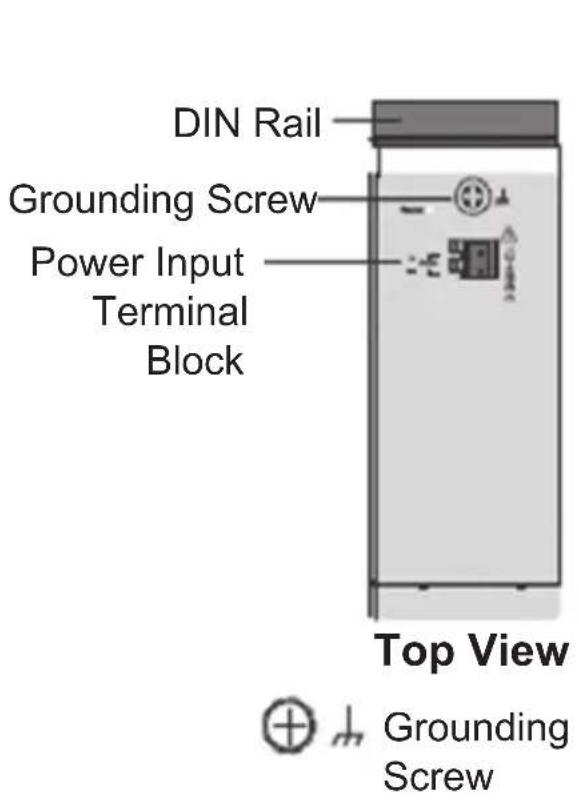
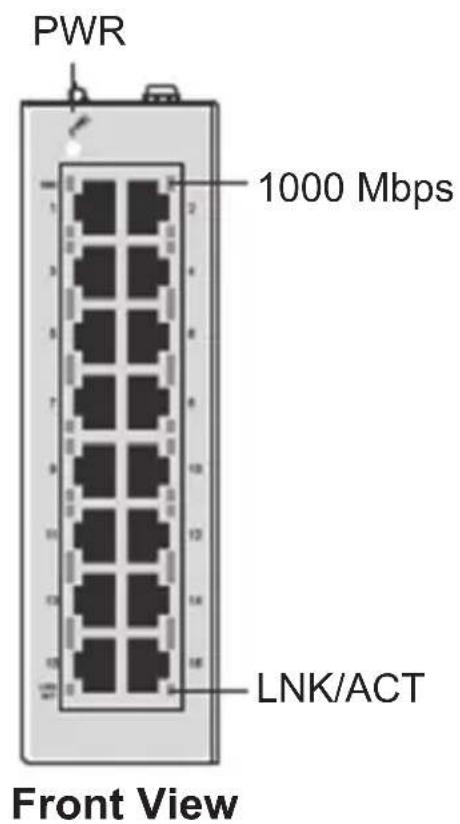
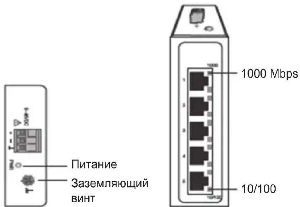
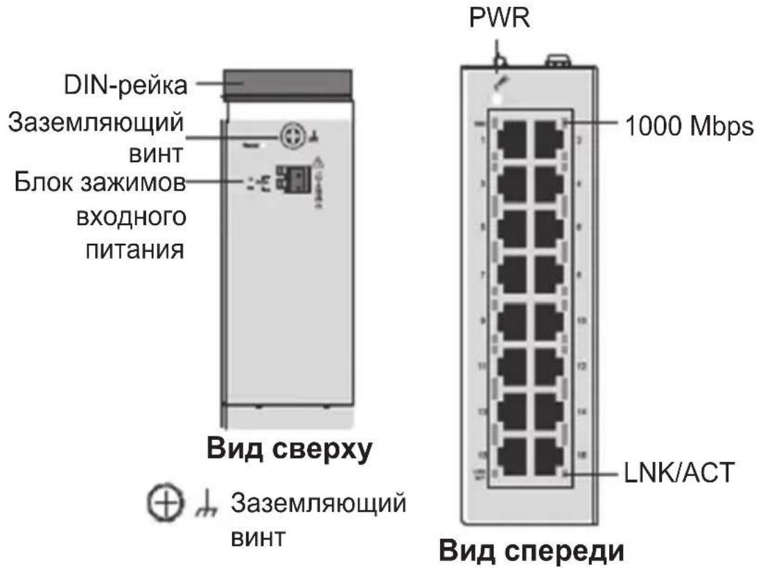
Product Overview
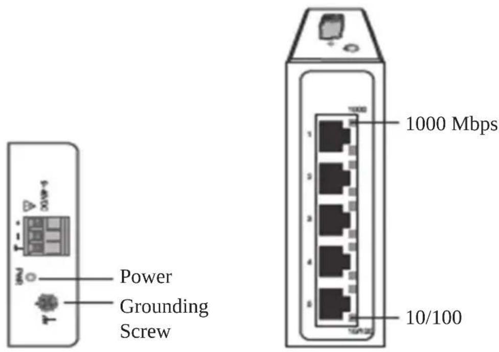
NGI-U05
Top View Front View
Product Overview
NGI-U16
DIN Mounting/Dismounting Instructions

ATTENTION: The NGI-U05 and NGI-U16 are open-type devices and shall be DIN mounted or wall mounted (NGI-U05 only) in a rack enclosure. The ambient temperature should not exceed 75^ (167^) .
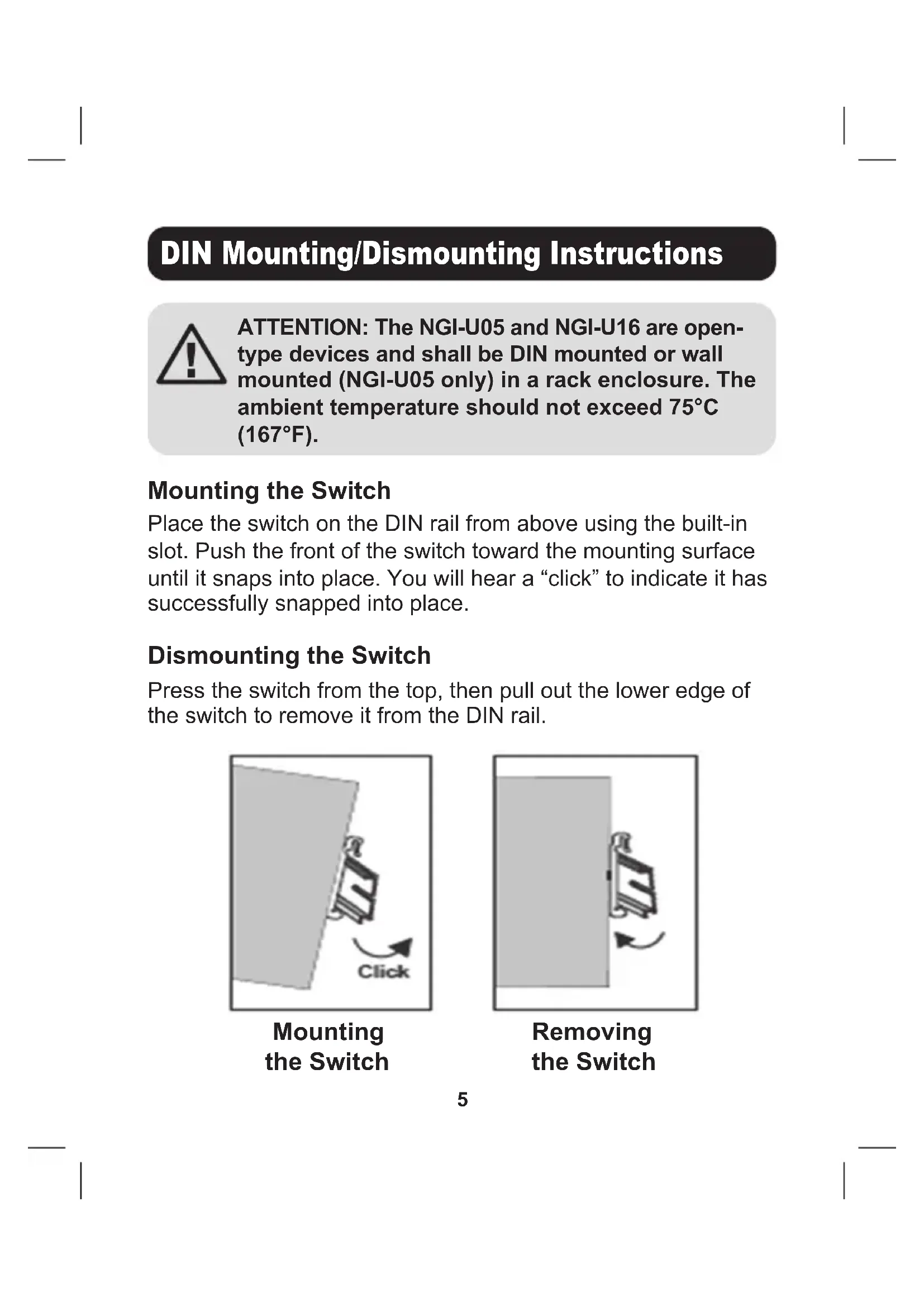
Mounting the Switch
Place the switch on the DIN rail from above using the built-in slot. Push the front of the switch toward the mounting surface until it snaps into place. You will hear a "click" to indicate it has successfully snapped into place.
Dismounting the Switch
Press the switch from the top, then pull out the lower edge of the switch to remove it from the DIN rail.
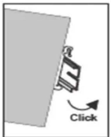
Mounting the Switch
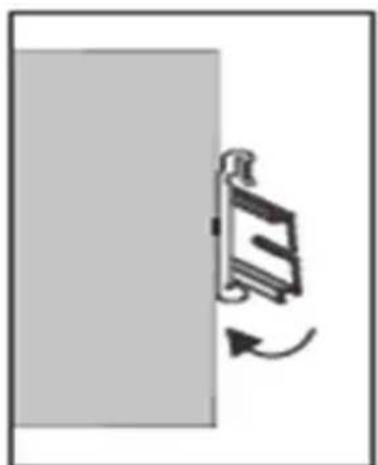
Removing the Switch
DIN Mounting/Dismounting Instructions

ATTENTION: A corrosion-free DIN mounting rail is advisable. When mounting the switch, be sure to allow enough space between devices to install the cabling and to ensure proper airflow.
Wall-Mounted Mask (NGI-U05 Only)
- Mount the switch by using mounting holes on the wall at the appropriate places.
1.5 mm - 3 mm
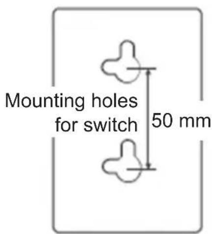
Mounting Holes Drawing of NGI-U05
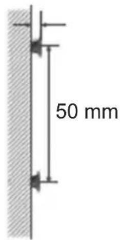
Screw Installation Distance
DIN Mounting/Dismounting Instructions
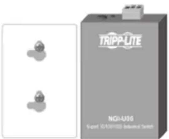
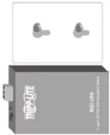
- The switch can be wall mounted either vertically or horizontally.
Note: Horizontal mounting is not evaluated by UL.
Mounting direction with screw
Straight Direction Installation
Mounting direction with screw
Horizontal Direction Installation
(Horizontal direction is not evaluated by UL)
Grounding the Switch
Grounding and wire routing help limit the effects of line noise caused by electromagnetic interference (EMI). Run the ground connection from the ground screw to the grounding surface prior to connecting devices.
ATTENTION: This switch is intended for mounting on a well-grounded surface, such as a metal panel.
Wiring Requirements
WARNING: Safety measures should be taken before connecting the power cable. Turn off the power before connecting modules or wires. The correct power supply voltage is listed on the product label. Check the voltage of your power source to make sure you are using the correct voltage. DO NOT use a voltage greater than what is specified on the product label. Calculate the maximum possible current in each power wire and common wire. Observe all electrical codes dictating the maximum current allowable for each wire size. If current exceeds the maximum rating, the wiring can overheat, causing serious damage to your equipment.
Please read and follow these guidelines:
- Use separate paths to route wiring for power and devices. If power wiring and device wiring paths must cross, make sure the wires are perpendicular at the intersection point.
Note: Do not run signal or communications wiring and power wiring through the same wire conduit. To avoid interference, wires with different signal characteristics should be routed separately. - You can use the type of signal transmitted through a wire to determine which wires should be kept separate. Wiring that shares similar electrical characteristics can be bundled together.
- You should separate input wiring from output wiring.
- Be advised that you should label the wiring to all devices in the system.
Wiring Requirements
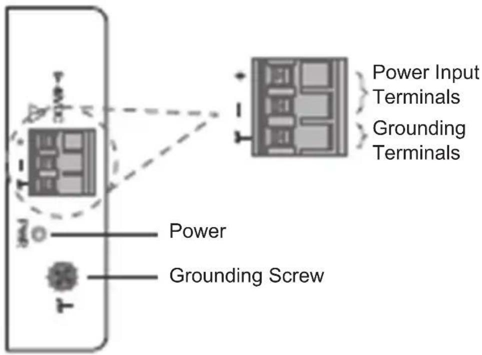
Wiring Power Input
NGI-U05 with 3-Pin Terminal Block
Check the polarity while connecting. Top view of the Terminal Block is shown in the figure below:
CAUTION:
- Use copper conductors only.
- Wiring cable temperature should support at least 105^ .
- Tighten the wire to a torque value 4.5 lb.in.
- The wire gauge for the terminal block should range between 12 and 24 AWG.
Wiring Requirements
To insert power wire and connect the 9~48VDC at a maximum of 0.5A DC power to the power terminal block, follow these steps:
- Use a flat-head screwdriver to loosen the wire-clamp screws.
- Insert the negative/positive DC wires into the (-12 +) terminals, respectively.
- Tighten the wire-clamp screws to prevent the wires from loosening.

ATTENTION: Use a power supply from 9~48VDC. The device power shall be supplied by SELV circuit.
NGI-U16 with 2-Pin Terminal Block
You can use "PWR" for power input. Top view of the Terminal Block is shown in the figure below:
12~48VDC
+
PWR
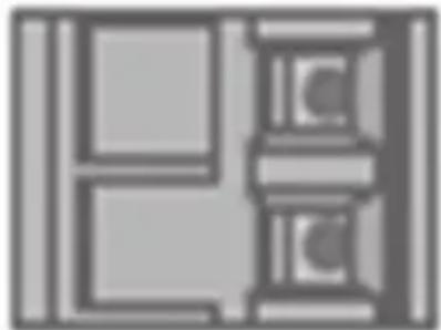
Terminal Block
Wiring Requirements
CAUTION:
- Use copper conductors only.
- Wiring cable temperature should support at least 105^ .
- Tighten the wire to a torque value 4.5 lb.in.
- The wire gauge for the terminal block should range between 12 and 24 AWG.
To insert power wire and connect the 12~48VDC at a maximum of 1.5A DC power to the power terminal block, follow these steps:
- Use a flat-head screwdriver to loosen the wire-clamp screws.
- Insert the negative/positive DC wires into the PWR-/PWR+ terminals, respectively.
- Tighten the wire-clamp screws to prevent the wires from loosening.

ATTENTION: Use a power supply from 12~48VDC. The device power shall be supplied by SELV circuit.
Cabling
Connect one end of an RJ45 Ethernet cable (see Optional Accessories) into the switch's RJ45 Ethernet port. Connect the other end to a network device. Cat5e cable or above is recommended.
All ports support Fast Ethernet and 10/100/1000 Ethernet (10/100/1000Base-T), as well as auto-negotiation and auto MDI/MDI-X to eliminate the need for crossover cabling.
LED Indicators
| PWR (Green) lllu | minated Pow | ver on by Terminal Block PWR |
| Off Terminal Block PWR fails or is unavailable | ||
| 1000 (Green) lllu | minated Link speed is 1000 Mbps (1 Gb) | |
| Blinking Data is transmitting/receiving | ||
| Off Link speed is 10/100 Mbps or link failed | ||
| 10/100 (Green) lllu | luminated Copper port link-up at 10/100 Mbps | |
| Blinking Data is transmitting/receiving | ||
| Off Link speed is 1000 Mbps (1 Gb) or link failed | ||
| LINK/ACT (Green) | llluminated Ethernet link-up | |
| Blinking Data is transmitting/receiving | ||
| Off Port disconnected or link failed | ||
Note: 10/100 LED only on NGI-U05. LINK/ACT LED only on NGI-U16.
Speed LED (100/1000) blinking function only on NGI-U05.
Environmental
| Operating Temperature -40°C to 75°C (-40°F to 167°F) | |
| Storage Temperature -40°C to 85°C (-40°F to 185°F) | |
| Maximum Altitude 2000 m | |
| Ambient Relative Humidity 5 to 95% (Non-Condensing) | |

ATTENTION: If the switch is used in a manner not specified here, the protection provided by the switch may be impaired.
Warranty and Product Registration
3-Year Limited Warranty
Seller warrants this product, if used in accordance with all applicable instructions, to be free from original defects in material and workmanship for a period of three (3) years from the date of initial purchase. If the product should prove defective in material or workmanship within that period, Seller will repair or replace the product, at its sole discretion.
THIS WARRANTY DOES NOT APPLY TO NORMAL WEAR OR TO DAMAGE RESULTING FROM ACCIDENT, MISUSE, ABUSE OR NEGLECT. SELLER MAKES NO EXPRESS WARRANTY OTHER THAN THE WARRANTY EXPRESSLY SET FORTH HEREIN. EXCEPT TO THE EXTENT PROHIBITED BY APPLICABLE LAW, ALL IMPLIED WARRANTYES, INCLUDING ALL WARRANTYES OF MERCHANTABILITY OR FITNESS, ARE LIMITED IN DURATION TO THE WARRANTY PERIOD SET FORTH ABOVE; AND THIS WARRANTY EXPRESSLY EXCULES ALL INCIDENTAL AND CONSEQUENTIAL DAMAGES. (Some states do not allow limitations on how long an implied warranty lasts, and some states do not allow the exclusion or limitation of incidental or consequential damages, so the above limitations or exclusions may not apply to you. This warranty gives you specific legal rights, and you may have other rights which vary from jurisdiction to jurisdiction.)
WARNING: The individual user should take care to determine prior to use whether this device is suitable, adequate or safe for the use intended. Since individual applications are subject to great variation, the manufacturer makes no representation or warranty as to the suitability or fitness of these devices for any specific application.
Product Registration
Visit tripplite.com/warranty today to register your new Tripp Lite product. You'll be automatically entered into a drawing for a chance to win a FREE Tripp Lite product! No purchase necessary. Void where prohibited. Some restrictions apply. See website for details.
WEEE Compliance Information for Tripp Lite Customers and Recyclers (European Union)
Under the Waste Electrical and Electronic Equipment (WEEE) Directive and implementing regulations, when customers buy new electrical and electronic equipment from Tripp Lite, they are entitled to:
- Send old equipment for recycling on a one-for-one, like-for-like basis (this varies depending on the country)
- Send the new equipment back for recycling when this ultimately becomes waste
Warranty and Product Registration
FCC Notice, Class B
This device complies with part 15 of the FCC Rules. Operation is subject to the following two conditions: (1) This device may not cause harmful interference, and (2) this device must accept any interference received, including interference that may cause undesired operation.
Note: This equipment has been tested and found to comply with the limits for a Class B digital device, pursuant to part 15 of the FCC Rules. These limits are designed to provide reasonable protection against harmful interference in a residential installation. This equipment generates, uses and can radiate radio frequency energy and, if not installed and used in accordance with the instructions, may cause harmful interference to radio communications. However, there is no guarantee that interference will not occur in a particular installation. If this equipment does cause harmful interference to radio or television reception, which can be determined by turning the equipment off and on, the user is encouraged to try to correct the interference by one or more of the following measures:
- Reorient or relocate the receiving antenna.
- Increase the separation between the equipment and receiver.
- Connect the equipment into an outlet on a circuit different from that to which the receiver is connected.
- Consult the dealer or an experienced radio/TV technician for help.
Any changes or modifications to this equipment not expressly approved by Tripp Lite could void the user's authority to operate this equipment.
Use of this equipment in life support applications where failure of this equipment can reasonably be expected to cause the failure of the life support equipment or to significantly affect its safety or effectiveness is not recommended.
Tripp Lite has a policy of continuous improvement. Specifications are subject to change without notice. Photos and illustrations may differ slightly from actual products.

1111 W. 35th Street, Chicago, IL 60609 USA · tripplite.com/support
1111 W. 35th Street, Chicago, IL 60609 USA • tripplite.com/support
1111 W. 35th Street, Chicago, IL 60609 USA • tripplite.com/support
Masque mural (NGI-U05 seulment)
1111 W. 35th Street, Chicago, IL 60609 USA • tripplite.com/support
PyKOBODCTBO
ПОЛьЗОВаТЕЛЯ
HeynpablernbIe
Помышлеснные
KOMMyTaTopbI Gigabit
Ethernet c podkIoueHneM
no texhoolorn Plug and Play
N BO3MOXHOCTbIO MOHTaJa
Mодели: NGI-U05, NGI-U16
English 1 • Espanol 17 • Français 33 • Deutsch 65
TRIPP·LITE
1111 W. 35th Street, Chicago, IL 60609 USA • triplite.com/support
OxpaHЯETcA aBTopCKIM npaBOM © 2022 Tripp Lite.
Pepeneutka 3anpeaaetc.
Copekmoe ynaKOBKn
- Kommytatop Gigabit Ethernet mOД. NGI-U05 nIIng NIg-U16
PykoBoDCTBO NOIb3OBaTeJIa
XapakTepnctnKn npoynkTa
- 5 (NGI-U05) Или 16 (NGI-U16) abTomatnueckn HactpanBaembIX nopToB RJ45 (10/100/1000 M6nt/c)
- Повдержka abTomatnieceко Функции nepekepecthoro coeINHeHnRA MDI/MDI-X
- Повдержka диаэоза pa6очх Temператур от -40 до 75°C
- Ierko BocnpnHmMaembIe CBeToNDnOHDhIe INHdNkaTOpbl NOKa3bIBaHT CTaTyc NOdkJIIOUcEHn I aKTHBHOCTn KaJDOrO nOpTa
-
CoOTBETCTByET cIeIyUOIM cTaNdapTaM IEEE:
-
IEEE 802.3 10Base-T
- IEEE 802.3u 100Base-T
- IEEE 802.3ab 1000Base-T
- IEEE 802.3 Auto Negotiation
-
IEEE 802.3x Flow Control
-
ПовдержИвает abTomatчecкoe obuchne n abTomatчeckyюТреникову по MAC-aDpecy
- Hadezhna peIbcoBa KneMma, yCTaHOBJIeHHa Ha 3aBoJeHn3rOToBnteNe, PNOTHo KpeNITcK JIO6oJ CTAHApTHOINpeKe IupnH0 35 MM*
- Прocтota установки по Тхнологи plug-and-play 6e3 Heo6xOДИМОCTи HabТpoйКи
*Пп汞анue. Bo3moxnocmb крpenneнua Ha DIN-peuky u hacmeHno20 moHmaka npedycmampuaemc monbko dny modenu NGI-U05
OnuHaJIbHbIe KOMJIeKToUcne
- Be3pa3pbBhIe UTP-ka6eH Cat5e (350 Mf) cepn N001
KpaTkoe onncanHe n3dJIIny
NGI-U05
BnD cBepxu BnD cpeeni
KpaTKoe onncanHe n3dJeJnIa
NGI-U16
Yka3aHnno KpenneHIO K DIN-peIKe / cHraTnIO c DIN-peiKn

BHMAHNE! MojeN NGI-U05 n NGI-U16 YBnIOTcY cTpoiCTBaMn OTkpblTO rTnA N MOHTnpUOTcHa DIN-peKe nIe cTeHe (ToIbKO mO. NGI-U05) BHyTpN IkaΦa. Tempeatypa OkpykaOuSeRo BO3dUxHa He DoJIxHa ppeBbIwAtb 75°C.
(20pu30hmaJIbHoe HappeHue He ouehuaemcKOMnHaue UL)
3a3eMJIeHne KOMMyTaTopa
3a3eMJIeHne I npOKnaIka npOBODOB NOMORAOT ORpaHnUBAbT B03JeCTBHe 7yMOB B IINHNI, Bbl3bIBaEMbIX 3JIeKTPOMaHHTHBIMI nomexamn (3M). Npeed nOdkIIOueHnem yCTpOJcTB npOBeDnte 3a3eMJIHOuIee COeHNHeHne OT BnHTa 3a3eMJIeHnK NOBepxHOCTN 3a3eMJIeHn.
BHUMAHNE! KommyTaTOp npedHa3HaueH dIa KpeIeHnK HaJeKHO 3a3emJIeHHo NOBepXHOCTN (HaNPmEp, MeTaNlueckO NaHeLI).
Tpe6obAHnK MOHTaJxU 3JIeKTpOpPoBODKn
BHIMAHNE! Npeed noKIOUeHnem Ka6eIaTHnHa Heo6xOdmo
PnHnTb Mepbl PpeIOCTOPOXHOCTN. OTKIOUaHTe 3JeKTPoNTaHne
peed noKIOUeHnEM MOyJIe IIN IPOBOOB. COOTBeTCTBYOUIe
HaPRAJKeHne nITaHnHa Yka3aHO Ha MapKIpOBKe I3DeJIy. IPOBepbTe
HaPRAJKeHne nCTOuHnKa IITaHnC CEJIbHO y6EiHTbcR B ERO COOTBE TCTBHN
YCTaHOBHeHHbIM Tpe6oBaHnM. HE nCNoJIb3yIte HAnpRAJKeHne,
IpeBbIaIOUeH HOMHaJI, Yka3aHHbI Ha MapKIpOBKe I3DeJIy.
PaCCHTaIte MaKcImaJIbHO BO3MOXhBI TK Upe3 KaJDbI CNIOBOI
IPOBOID N HeITpaJIbHI pIOBOd. Co6JIOnaIte BCE 3JeKTPoTeHXueCKNe
HOpMbI IN PpaBnla, PpeDINCSbIAIOUeMaKcImaJIbHO DOYNCTUMBI TK DJIa
KaJDoTO KaIIbpa IPOBOOB. IpeBbIseHne MaKcImaJIbHO DOYNCTUMORO
3NaueHnra TOKa MoXeT PpNBecTI K NepeRpeBy 3JeKTPoNPoBOdKn,
BbI3bBAIOUeMy Cepbe3Hoe NOBpeXdeHne O6OpUDoAHnI.
O3HaKOMbTecb c HactoIIMN yKa3aHnA M N cIeDyIte I M:
- IcnoIb3yIte pa3dJIbHbIe MapwpyTbI npOKJaIKn CINOBbIX npOBOOB IN npOBOOB dIa coEINHeHry yCTpOiCTB. B cIyae Heo6XoIMocTIn nepceueHn MaPwpyTOB nPOKJaIKn CINOBbIX npOBOOB IN npOBOOB dIa CoEINHeHry yCTpOiCTB yKa3aHHbIe npOBOda DOJXHbI npOXODITb nepneHNkUyRPhO dpyr dpyr BV TOKe nepceueHn.
Ipumeyane. He npoknaebiaume cuhaibhyu unu cnaobomouhyo npoeodky 8 odHom ka6epepoBode c cunooei npoBODko. Bo u3bexaHue nomex npoeoda c pa3nUHbIMCUaHaNbHbIMU xapakmepucmu kAMU doJxHbI npoknaebambcra pa3deJIbHO. - Дя onpeдени.ToR, kakne npoBoa cJeDyET npoknaIbIbTb pa3delenbHO, MoxHo nCNoJIb3OBaT bTn CnHaJa, nepeDaBaEMoro no npoBOy. PpOBoa c aHaJIoNHyIMN 3JIeKTpUcEckmM xapaKTePncTnKaMn MOrYt OBeEnHrTbcB B JkryT.
BxoHa 3JleKtpoPoBOKa DOJXHa 6bITb OTDeJeHa OT BbIXoHoi.
CneIyET obpaTb BnMaHne Ha Heo6XoIMOCTb MapKInPOBKn IPOBOIOB, PpOKIaIbIiBaEmbIX KO BCem yCTpoINCTBaM B CnCTeMe.
Tpe6obAHnK MOHTaJxU 3JIeKTpOpOBoDKn
MONTAX CINIOBORO BXODA
Moi. NGI-U05 c 6Jokom 3-KoHTaKTHbIX 3axIMOB
IpoBepbTe noJapHocTb npn noKJIuOeHnn. BnD 6Joka 3aXIMOB CBepxY noka3aH Ha npNBedeHHOM HIXe pncyHke:
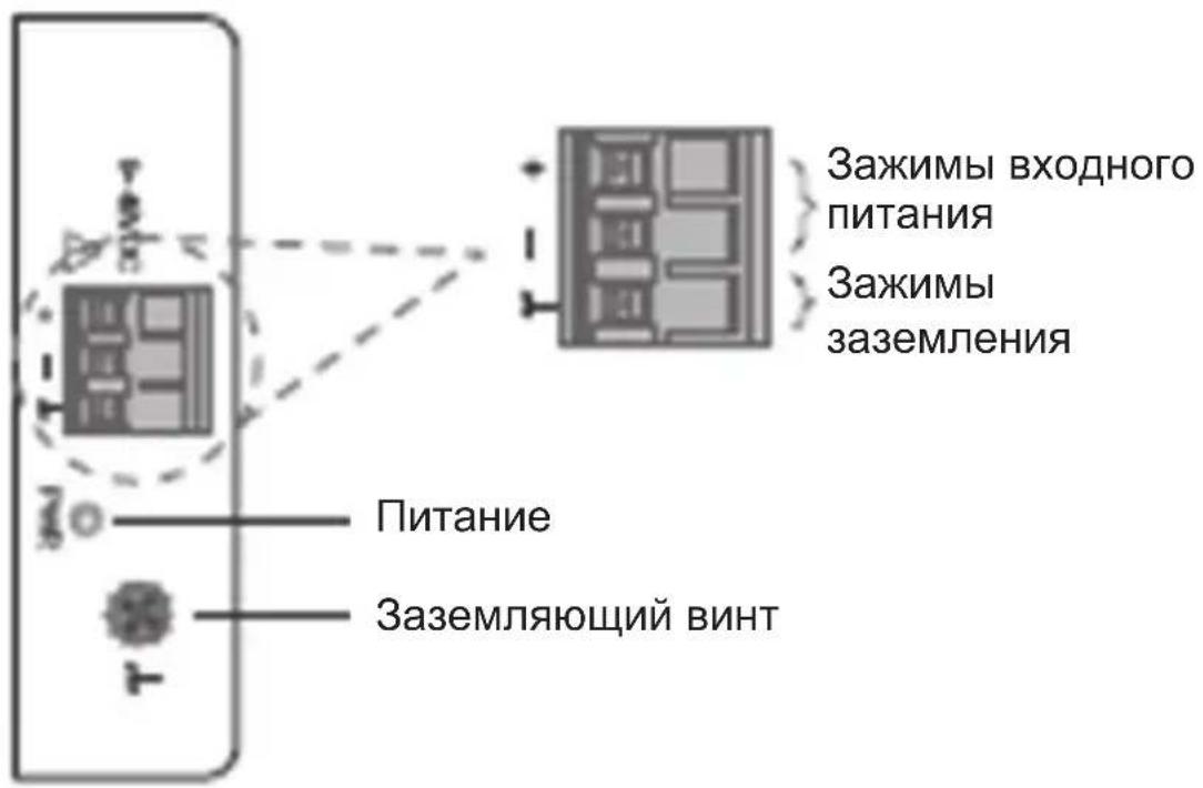
BHIMAHNE!
- IcnoIb3yIe ToJIbKO MeIhIe npOBODHKn.
- MoNTaXHbI Ka6eJIb DoJIKeH NOДePKeINBaTb TempePaTyPy He MeHee 105^
3aTnBaTe npoBOna C yCInnem 4,5 H-IOHMbl - Пгимechаим. Рп монтаже каллбр побовдя 6лoka 3жIMOB Должен НхоДиТьсь В диana3оHe ot 12do 24 AWG.
Tpe6obAHnK MOHTaJxU 3JIeKTpOpnpOBoDKN
CBeToIIOHbIe HnIkaTOpbl
| PWR (Зелень) | Горот Вк | Починые пitaиме чeredо 6лok зжимов PWR |
| Выкл Блор Балор Балор Балор Балор Балор Балор Балор Балор Балор Балор Балор Балор Балор Балор Балор Балор Балор Балор Балор Балор Балор Балор Балор Балор Балор Бalamor Балор Балор Балор Балор Балор Балор Балор Балор Балор Балор Балор Балор Балор Балор Балор Балор Балор Балор Балор Балор Балор Балор Балор Балор Балor Балор Балор Балор Балор Балор Балор Балор Балор Балор Балор Балор Балор Балор Балор Балор Балор Балор Балор Балор Балор Балор Балор Балор Балор Бalamore Балор Балор Балор Балор Балор Балор Балор Балор Балор Балор Балор Балор Балор Балор Балор Балор Балор Балор Балор Балор Балор Балор Балор Балор Балlor Балор Балор Балор Балор Балор Балор Балор Балор Балор Балор Балор Балор Балор Балор Балор Балор Балор Балор Балор Балор Балор Балор Балор Балор БалOR БалOR БалOR БалOR БалOR БалOR БалOR БалOR БалOR БалOR БалOR БалOR БалOR БалOR БалOR БалOR БалOR БалOR БалOR БалOR БалOR БалOR БалOR БалOR БалOR Балор БалOR БалOR БалOR БалOR БалOR БалOR БалOR БалOR БалOR БалOR БалOR БалOR БалOR БалOR БалOR БалOR БалOR БалOR БалOR БалOR БалOR БалOR БалOR БалORE БалOR БалOR БалOR БалOR БалOR БалOR БалOR БалOR БалOR БалOR БалOR БалOR БалOR БалOR БалOR БалOR БалOR БалOR БалOR БалOR БалOR БалOR БалOR БалOR БалORA БалOR БалOR БалOR БалOR БалOR БалOR БалOR БалOR БалOR БалOR БалOR БалOR БалOR БалOR БалOR БалOR БалOR БалOR БалOR БалOR БалOR БалOR БалOR БалOR Бал OR БалOR БалOR БалOR БалOR БалOR БалOR БалOR БалOR БалOR БалOR БалOR БалOR БалOR БалOR БалOR БалOR БалOR БалOR БалOR БалOR БалOR БалOR БалOR БалOR БалORTC БалOR БалOR БалOR БалOR БалOR БалOR БалOR БалOR БалOR БалOR БалOR БалOR БалOR БалOR БалOR БалOR БалOR БалOR БалOR БалOR БалOR БалOR БалOR БалOR БалTOR БалOR БалOR БалOR БалOR БалOR БалOR БалOR БалOR БалOR БалOR БалOR БалOR БалOR БалOR БалOR БалOR БалOR БалOR БалOR БалOR БалOR БалOR БалOR БалOR БалORG БалOR БалOR БалOR БалOR БалOR БалOR БалOR БалOR БалOR БалOR БалOR БалOR БалOR БалOR БалOR БалOR БалOR БалOR БалOR БалOR БалOR БалOR БалOR БалOR БалOr БалOR БалOR БалOR БалOR БалOR БалOR БалOR БалOR БалOR БалOR БалOR БалOR БалOR БалOR БалOR БалOR БалOR БалOR БалOR БалOR БалOR БалOR БалOR БалOR Бал図 БалOR БалOR БалOR БалOR БалOR БалOR БалOR БалOR БалOR БалOR БалOR БалOR БалOR БалOR БалOR БалOR БалOR БалOR БалOR БалOR БалOR БалOR БалOR БалOR БалORD БалOR БалOR БалOR БалOR БалOR БалOR БалOR БалOR БалOR БалOR БалOR БалOR БалOR БалOR БалOR БалOR БалOR БалOR БалOR БалOR БалOR БалOR БалOR БалOR БалORM БалOR БалOR БалOR БалOR БалOR БалOR БалOR БалOR БалOR БалOR БалOR БалOR БалOR БалOR БалOR БалOR БалOR БалOR БалOR БалOR БалOR БалOR БалOR БалOR БалORS БалOR БалOR БалOR БалOR БалOR БалOR БалOR БалOR БалOR БалOR БалOR БалOR БалOR БалOR БалOR БалOR БалOR БалOR БалOR БалOR БалOR БалOR БалOR БалOR БалSOR БалOR БалOR БалOR БалOR БалOR БалOR БалOR БалOR БалOR БалOR БалOR БалOR БалOR БалOR БалOR БалOR БалOR БалOR БалOR БалOR БалOR БалOR БалOR БалOR БалAND БалOR БалOR БалOR БалOR БалOR БалOR БалOR БалOR БалOR БалOR БалOR БалOR БалOR БалOR БалOR БалOR БалOR БалOR БалOR БалOR БалOR БалOR БалOR БалOR БалORY БалOR БалOR БалOR БалOR БалOR БалOR БалOR БалOR БалOR БалOR БалOR БалOR БалOR БалOR БалOR БалOR БалOR БалOR БалOR БалOR БалOR БалOR БалOR БалOR БалORB БалOR БалOR БалOR БалOR БалOR БалOR БалOR БалOR БалOR БалOR БалOR БалOR БалOR БалOR БалOR БалOR БалOR БалOR БалOR БалOR БалOR БалOR БалOR БалOR БалR БалR БалR БалR БалR БалR БалR БалR БалR БалR БалR БалR БалR БалR БалR БалR БалR БалR БалR БалR БалR БалR БалR БалR БалR БалOR БалR БалR БалR БалR БалR БалR БалR БалR БалR БалR БалR БалR БалR БалR БалR БалR БалR БалR БалR БалR БалR БалR БалR БалOR БалOR БалR БалR БалR БалR БалR БалR БалR БалR БалR БалR БалR БалR БалR БалR БалR БалR БалR БалR БалR БалR БалR БалR БалOR БалR БалOR БалR БалR БалR БалR БалR БалR БалR БалR БалR БалR БалR БалR БалR БалR БалR БалR БалR БалR БалR БалR БалR БалR БалOR БалOR БалOR БалR БалR БалR БалR БалR БалR БалR БалR БалR БалR БалR БалR БалR БалR БалR БалR БалR БалR БалR БалR БалR Балr БалR БалR БалR БалR БалR БалR БалR БалR БалR БалR БалR БалR БалR БалR БалR БалR БалR БалR БалR БалR БалR БалR БалR БалR Балr БалR БалR Балr БалR БалR БалR БалR БалR БалR БалR БалR БалR БалR БалR БалR БалR БалR БалR БалR БалR БалR БалR БалR БалR Балr БалR БалR БалI R БалR BalloR BalloR BalloR BalloR BalloR BalloR BalloR BalloR BalloR BalloR BalloR BalloR BalloR BalloR BalloR BalloR BalloR BalloR BalloR BalloR BalloR BalloR BalloR BalloR BalloR BalleR BalleR BalleR BalleR BalleR BalleR BalleR BalleR BalleR BalleR BalleR BalleR BalleR BalleR BalleR BalleR BalleR BalleR BalleR BalleR BalleR BalleR BalleR BalleR BalleR Ballesty |
Ipumeyue. Cn1 10/100 umeemc mojko ha mod.NGI-U05.CnLINK/ACT umeemc mojko ha mod.NGI-U16.ФункuaMuzaHuaCn1(100/1000)c bicokou yacmomou umeemc mojko ha mod.NGI-U05.