V2P5G43 - Desktop computer ASUS - Free user manual and instructions
Find the device manual for free V2P5G43 ASUS in PDF.
| Product Type | Desktop computer (barebone system) |
| Brand | ASUS |
| Model | V2P5G43 |
| Dimensions (approx.) | 180 x 420 x 380 mm |
| Weight (approx.) | 10 kg |
| Power Supply | 350 W, voltage selector 115/230 V |
| Supported Processors | Intel Pentium 4 (LGA775) or AMD (compatible socket) |
| Memory | DDR DIMM, number of slots not specified |
| Storage | 1 x 5.25" bay (optical drive), 1 x 3.5" bay (floppy), 1 x 3.5" bay (hard disk), SATA or IDE interface |
| Front Panel Connectors | 2 USB 2.0 ports, headphone jack, microphone jack, Power button, Reset button, HDD LED |
| Rear Panel Connectors | PS/2 keyboard and mouse, VGA, parallel, 4 USB 2.0 ports, RJ-45 LAN, E-SATA or COM1 serial or DVI, optical S/PDIF, IEEE 1394a, 6/8-channel audio |
| Expansion Slots | Several slots (type not specified), metal shields |
| Maintenance and Cleaning | Unplug the device, dust the interior with compressed air, clean connectors with a soft cloth |
| Safety | Unplug before servicing, use the voltage selector appropriate for your region, do not force components during installation |
| Spare Parts and Repairability | ASUS motherboard, CPU fan, standard ATX power supply, standard 5.25" and 3.5" bays, IDE/SATA cables included |
| General Information | Barebone system, installation manual provided, selectable input voltage |
Frequently Asked Questions - V2P5G43 ASUS
User questions about V2P5G43 ASUS
0 question about this device. Answer the ones you know or ask your own.
Ask a new question about this device
Download the instructions for your Desktop computer in PDF format for free! Find your manual V2P5G43 - ASUS and take your electronic device back in hand. On this page are published all the documents necessary for the use of your device. V2P5G43 by ASUS.
USER MANUAL V2P5G43 ASUS
ASUS PC (Desktop Barebone)
Installation manual

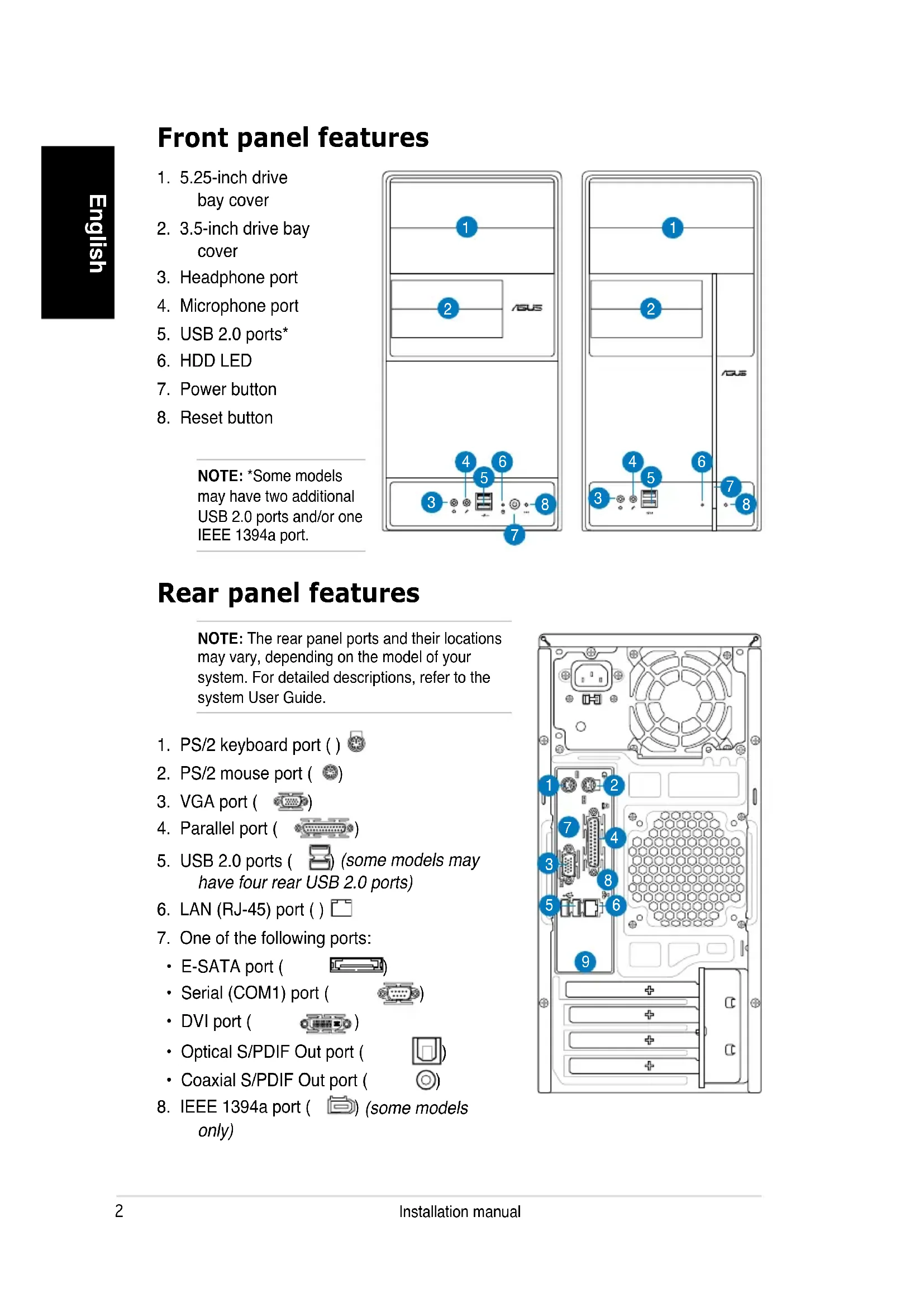
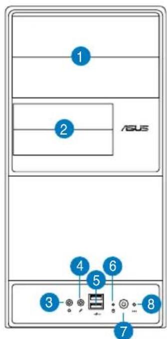
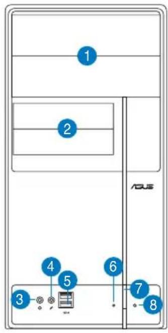
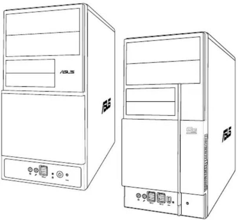
Front panel features
- 5.25-inch drive bay cover
- 3.5-inch drive bay cover
- Headphone port
- Microphone port
- USB 2.0 ports*
- HDD LED
- Power button
- Reset button
NOTE: *Some models may have two additional USB 2.0 ports and/or one IEEE 1394a port.
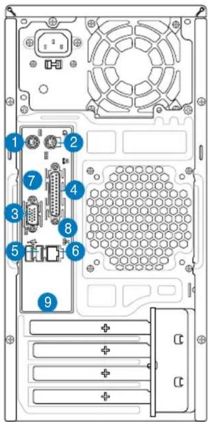
Rear panel features
NOTE: The rear panel ports and their locations may vary, depending on the model of your system. For detailed descriptions, refer to the system User Guide.
- PS/2 keyboard port ()
- PS/2 mouse port (
- VGA port (
- Parallel port (
- USB 2.0 ports ( some models may have four rear USB 2.0 ports)
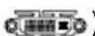
6.LAN (RJ-45) port () - One of the following ports:
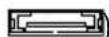
E-SATA port (
- Serial (COM1) port (

- DVI port (
- Optical S/PDIF Out port (

Coaxial S/PDIF Out port (

8.IEEE 1394a port ( ) (some models only)
-
One of the following audio ports configurations:
-
6-channel
8-channel
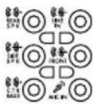
Refer to the configuration table in the User Guide for details.
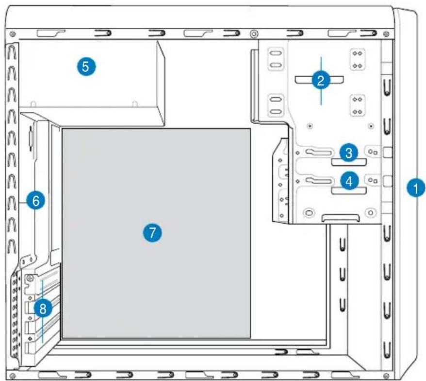
Internal components
-
Front panel cover
-
Power supply unit
-
5.25-inch optical drive bays
-
Chassis fan slot
-
Floppy disk drive bay
-
ASUS motherboard*
-
Hard disk drive bay
-
Expansion slot metal brackets
NOTE: *Refer to the system User Guide for motherboard details.
Selecting the voltage
The system's power supply unit has a 115 V/230 V voltage selector switch located beside the power connector. Use this switch to select the appropriate system input voltage according to the voltage supply in your area.
If the voltage supply in your area is 100-127 V, set the switch to 115 V.
If the voltage supply in your area is 200-240 V, set the switch to 230 V.
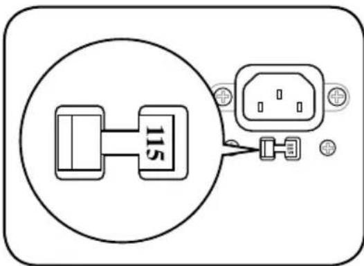
NOTE: Refer to the system User Guide for the exact location of the voltage selector.
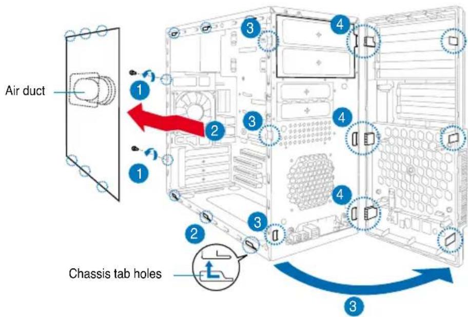
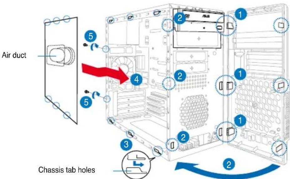
Removing the side cover and front panel assembly
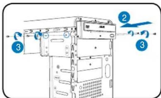
- Remove the cover screws on the rear panel.
- Pull the side cover toward the rear panel until its hooks disengage from the chassis tab holes. Set the side cover aside.
- Locate the front panel assembly hooks, then lift them until they disengage from the chassis.
- Swing the front panel assembly to the right, until the hinge-like tabs on the right side of the assembly are exposed.
- Remove the front panel assembly, then set aside.
Installing a CPU
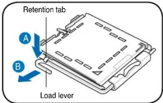
Installing an Intel Pentium 4 CPU in the LGA775 package
- Locate the CPU socket on the motherboard.
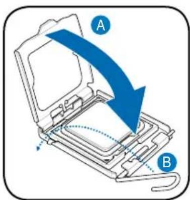
- Press the load lever with your thumb (A), then move it to the left (B) until it is released from the retention tab.
CAUTION. To prevent damage to the socket pins, do not remove the PnP cap unless you are installing a CPU.
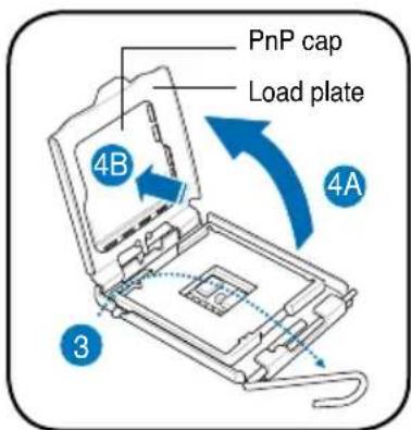
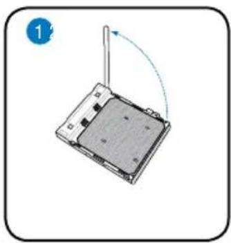
- Lift the load lever in the direction of the arrow to a 135^ angle.
- Lift the load plate with your thumb and forefinger to a 100^ angle (4A), then push the PnP cap from the load plate window to remove (4B).
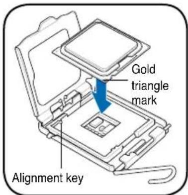
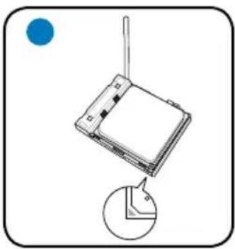
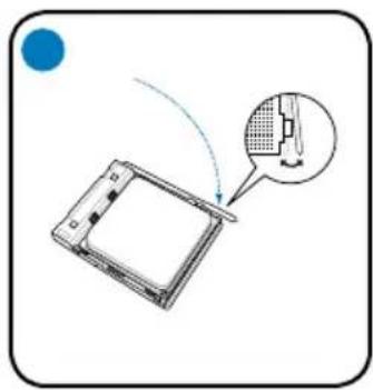
- Position the CPU over the socket, making sure that the gold triangle is on the bottom-left corner of the socket. Fit the socket alignment key into the CPU notch.
- Close the load plate (A), then push the load lever (B) until it snaps into the retention tab.

Installing an AMD CPU
- Locate the CPU socket, then lift the socket lever to a 90^ angle.
- Install the CPU to the socket, making sure that the CPU corner with the gold triangle matches the socket corner with a small triangle.
- Push down the socket lever to secure the CPU.
CAUTION: Incorrect installation of the CPU into the socket may bend the pins and severely damage the CPU!
Installing the CPU fan and heatsink assembly
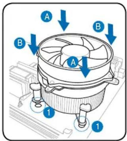
Installing an Intel® Pentium® 4 CPU heatsink and fan
- Place the heatsink on top of the installed CPU, making sure that the four fasteners match the holes on the motherboard.
- Push down two fasteners at a time in a diagonal sequence to secure the heatsink and fan assembly in place.
- When the fan and heatsink assembly is in place, connect the CPU fan cable to the connector on the motherboard.
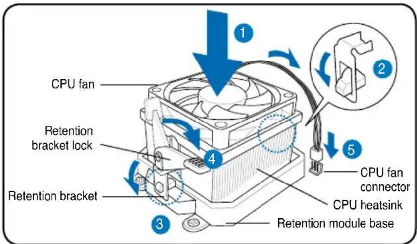
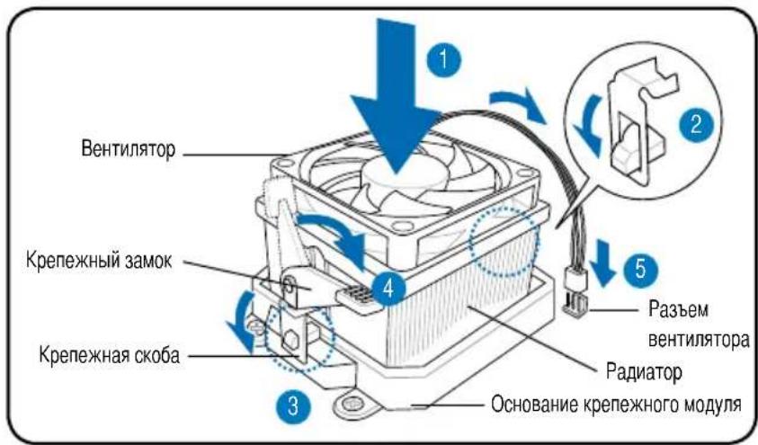
Installing an AMD CPU heatsink and fan
- Place the heatsink on top of the installed CPU.
IMPORTANT. Make sure that the fan and heatsink assembly perfectly fits the retention mechanism module base; otherwise you can not lock the retention bracket.
- Attach one end of the retention bracket to the retention module base.
- Attach the other end of the retention bracket (near the retention bracket lock) to the retention module base until it clicks in place.
NOTE. Your boxed CPU should come with installation instructions for the CPU, fan/heatsink assembly, and the retention mechanism. If the instructions in this section do not match the CPU documentation, follow the latter.
- Push down the retention bracket lock on the retention mechanism to secure the fan and heatsink to the module retention module base.
- Connect the CPU fan cable to the connector on the motherboard.
CAUTION. Do not forget to connect the CPU fan connector! Hardware monitoring error can occur if you fail to plug this connector.

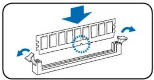
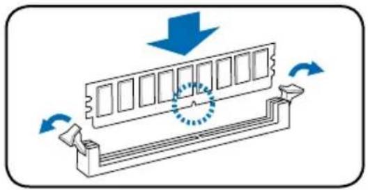
Installing a DIMM
- Locate the DIMM sockets in the motherboard.
- Unlock a DIMM socket by pressing the retaining clips outward.
- Align a DIMM on the socket such that the notch on the DIMM matches the break on the socket.
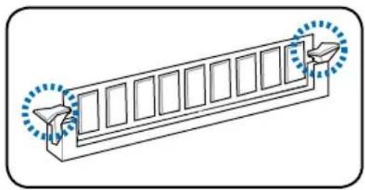
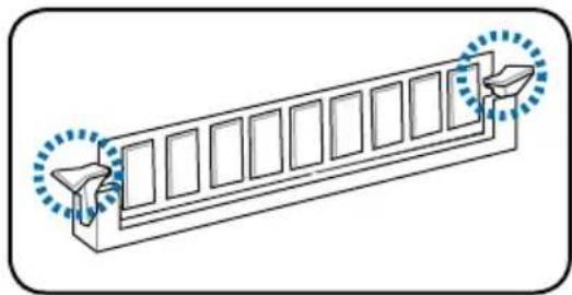
- Push the DIMM to the socket until the retaining clips snap inward.
CAUTION:
- Unplug the power supply before adding or removing DIMMs. Failure to do so may cause damage to the motherboard and/or components.
- A DDR DIMM is keyed with a notch so that it fits in only one direction. Do not force a DIMM into a socket to avoid damaging the DIMM.
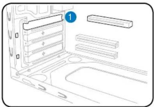
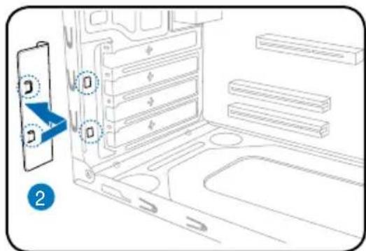
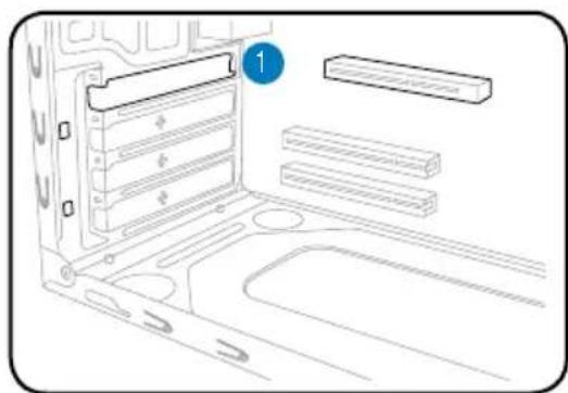
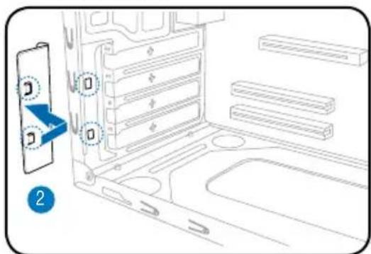
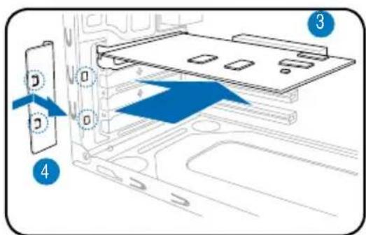
Installing an expansion card
the slot that you intend to use.
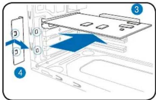
- Insert the card connector to the slot, then press the card firmly until it fits in place.
-
Replace the metal bracket lock.
-
Remove the metal bracket lock.1. Remove the metal
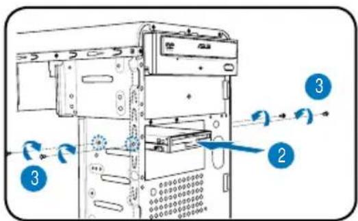
Installing storage drives
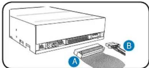
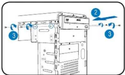
Optical drive
- Place the chassis upright, then remove the upper 5.25" drive bay metal plate cover.
- Insert the optical drive to the bay, then carefully push the drive until its screw holes align with the holes on the bay.
- Secure the optical drive with two screws on both sides of the bay.
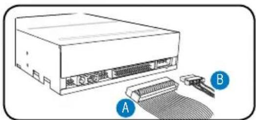
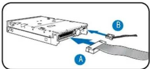
- Connect the IDE (A) and power (B) plugs to connectors at the back of the drive.
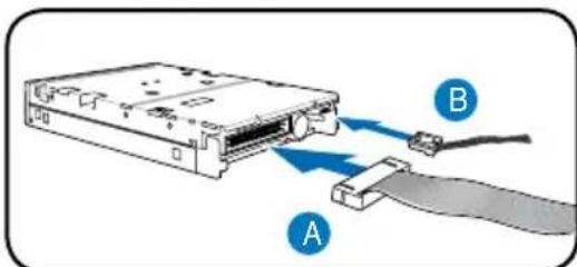
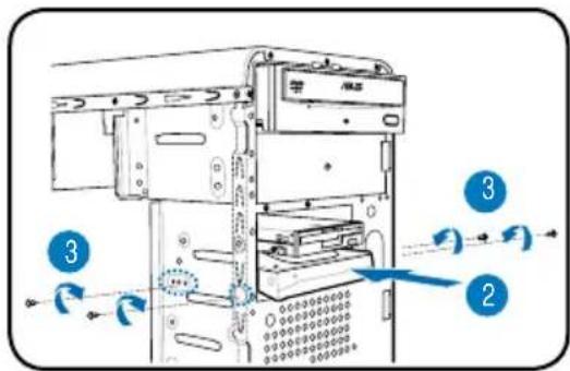
Floppy disk drive
- Place the chassis upright, then remove the lower 3.5" drive bay metal plate cover.
- Insert the floppy disk drive to the bay, then carefully push the drive until its screw holes align with the holes on the bay.
- Secure the floppy disk drive with two screws on both sides of the bay.
- Connect the signal (A) and power (B) plugs to connectors at the back of the drive.
Hard disk drive
- Place the chassis upright, then remove the upper 3.5" drive bay metal plate cover.
- Insert the hard disk drive to the bay, then carefully push the drive until its screw holes align with the holes on the bay.
- Secure the hard disk drive with two screws on both sides of the bay.
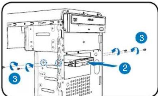
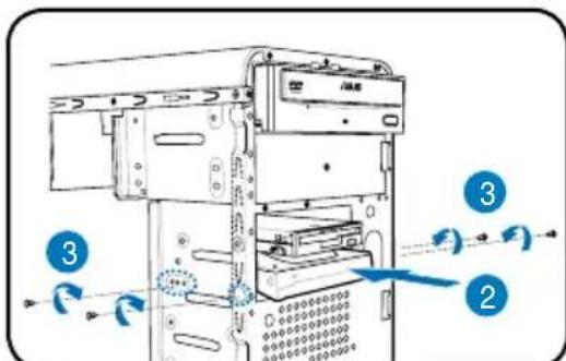
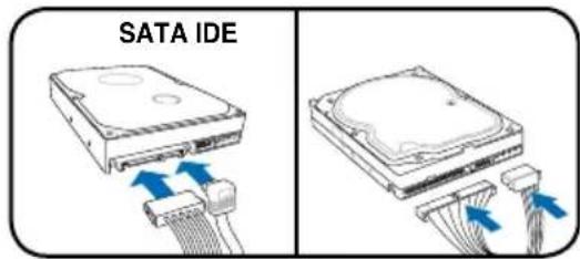
- For SATA HDD: Connect the SATA signal and power plugs to the connectors at the back of the drive.
For IDE HDD: Connect the IDE and power plugs to the connectors at the back of the drive.
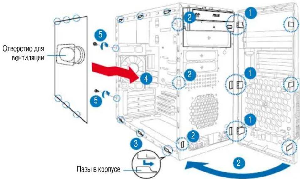
Removing the bay covers and reinstalling the front panel assembly and side cover
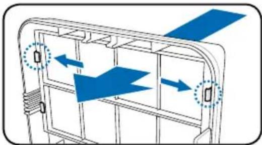
If you installed an optical and/or floppy disk drive, remove the bay cover(s) on the front panel assembly before reinstalling it to the chassis. To do this:
- Locate the bay cover locks.
- Press the locks outward to release the bay cover.
- Push the bay cover inward, then set it aside.
- Follow the same instructions to remove the 3.5" drive bay cover.
To reinstall the front panel assembly and side cover:
- Insert the front panel assembly hinge-like tabs to the holes on the right side of the chassis.
- Swing the front panel assembly to the left, then insert the hooks to the chassis until the front panel assembly fits in place.
- Insert the six side cover hooks into the chassis tab holes.
- Push the side cover to the direction of the front panel until it fits in place.
- Secure the cover with two screws you removed earlier.
ASUS
V-Série
- Port S/PDIF Out coaxial (

ASUS PC (Desktop Barebone)
Installationshandbuch
Frontseite
ASUS PC (Desktop Barebone)
- PnKpeHrTe OIN KOHeu CkObbl K OCHOBaHIO KpeIeXHOro MoDyJIa.
- 3aueKnTe npyTo KoneC kO6b(OKoIO 3amka ck6bl) C OCHOBaHnEM KpeNEXHO MOnyIJI. UeUOK 03Naayet, YTO CK6Ba BCTana Ha MeCTO.
PIMMEYAHNE. BmecTe c npoeccopom B kopo6oHOn KOMnEeKaun eCTb nHcTpyKuaNo yctaHOBe npoecoppa, paiaTopa N KpeJexHo r MexaHn3Ma. EcnO OHn OTnauOTc r O nHcTpyKuB D aHHOM pa3dene, pyKOBOCTByTEc b DOkymeHTaune K npoeccopy.
- Haxmte Ha KpeJexHbIe 3amKn dJa 3aKpeJIeHnpaDnATopa N BeHTnJIaTopa K OCHOBAHIO MOdYJIa.
- NookhOnite Ka6eJIb BeHTnJIaTopa Ka3bemy Ha MaTePHCKoI nIaTe.
BHIMAHHE. He 3abTe NOKIOHTb BEHTIaTOp! EcIN Bbl 3TOrO He cdeJaTe, MOry T Bo3HnKHyTb Ow6Kn KOHTpOJIOBOpUdOBaHn.
YctaHOBka MOdUeN pAmrTIN DIMM
- HainTe rHe3da DIMM Ha MaTeOpHcKoI pIaTe.
- Pa36IOKpyTe rHe3do DIMM, OTXaB CTOPOhbl dNKcaTopbl.
- CoBmecTeMoIb DIMM C rHe3dOM TaK, YTO6bI Na3 Ha MoIyIe COBnAaI C BbICTyIOM B rHe3JIe.
- BdABTe MoyIb DIMM B rHe3do, noka KpeNexKhble 3aueJkn He BepHyTcB 3akpbItoe IIOJOxKeHne.
BHIMAHNE:
BoBpemyyctahOBKINCHTnMOnyIeIMDIMMOTKJIIOHTeNITaHHe.BnpoTHBOMcYuaeMOXHO NOBpeDNTb MATEPHCKVIOIIaTVN/IMNKOMPOHEHTbl.
ModyNb DDR DIMM chabxhen BbIeMKo, yTO6bl erO MOxHO 6blno yCTaHOBnTb TOnbKO B OdHOM HappaBHeHH. HE npImehyte cnny npn yCTaHOBe Moynr DIMM Br He3do, yTO6bl PpeDfTBPaNTb erO nobpeKJeHne.
YctaHOBKa KapTbI paCUnpeHnA
- CHIMITE metaJIINueckyI nnAHHKy.
- CHIMITE MeTALIeCKyO KpbIuKy HAnpoTnB IHe3da, KOtOpoe BbXOTnTe NcNoJIb30BaTb.
- BCTaBbTe pa3bEm KapTbI B rHe3do, 3aTEM HaxMMTE C yCnJIeM, NOKa KapTa He BCTaHET Ha MecTo.
- NocTaBbTe MeTaJIInueckyIOIinaKy.
YCTaHOBKa yCTpoiCTB xpaHeHnaHHbIX
OnTuYeckn npuBOd
- YctaHOBnTe KOpNc BepTnKaJIbHo N ydaJIte 3aIuTHyO MeTaJINuYeCKyO nlaCTnHy, 3akpbIBaIOUoOTceK.
2.BCTaBTe npuBOD B BepxHn 5.25- IIOHMOBbI OTcEK N OCTOpOxH0 TOJkaTte ero BHyTp, noka erO OTBepCTnI DJI BnHTOB He COBnaDyT C OTBepCTnAM OTEcKa. - 3akpeHnTe npBOD DByM BnHTamN C DByX CTOpOH OTceKa.
4.Поdkлочтete kabeJI INIDE(A),nntaHnB(B).
ДиСКOBOD
- YctaHOBnTe KOpNc BepTKKaJIbHo I ydaIInTe 3aUHTHyO MetaIINuYeCKyIO IIaCTnHy, 3aKpbIBaIOu HxKnH 3.5- IOHMBoi OTceK.
2.Octopoxho BCTaBTe DnCKOBoB BHyTpB, IOKa eO OTBepCTnI BnHTOB He COBnaDyT C OTBepCTnMnOTcKa. - 3aKpeNITe INCKOBOD IByM BnHTAMN C DByX CTOpOH.
4.ПоdkнчiteKa6eNcHnBh(A)m nHTaHn(B).
KecTKn DnCK
- YctaHOBInTe KOpnyc BepTNKaJIbHo n ydaJIte 3aUHTHyO MetaIIINueCKyIO pIacTHHy, 3aKpbIBaHOuYIO BepXHm 3.5- IOHMOBbI OTcEK.
2.BCTaTe JecTkn DnCK BOTcK N OCToPoxHo TOnKaIte erO BHyTpB, NOka erO OTBePCTnIg BNHTOB He COBnaDyTC OTBePCTnMn OTcKa. - 3aKpeIte JxecTKn DnCK DByMa BnHTamN C DByX CTOpOH.
4.ДЯВHueCTepaSATA:ПОДКИЧУTe Ka6eNSerial ATAиптаня.
IyctaHOBKnpeepnHaHeNb60KOBbIXCTeHOK:
- BCTaBbTe nETnI nepeDHe naneHn B OTBepTna Ha npabOi CTopoHE KOpnyca.
- 3akpbBaIte nepeNDIO naHeJIb, noka OHa He BCTaHET Ha MeCTO.
- YctaHOBtTe BbCTybl6OKOBON CTeHN B OTBepCTnB KOpnyce.
- TOnkaTe CTeHky no HappaBHeHIO K nepeDnei naHeJI, noka OHa He BCTaHET Ha MeCTO.
5.3aKpeINTE CTeHky DByMRA BnHTaM.
V-Série
ASUS PC (sistema barebone para desktop)
Manual de instalacao