
CK 20 Premium - Heating STIEBEL ELTRON - Free user manual and instructions
Find the device manual for free CK 20 Premium STIEBEL ELTRON in PDF.
| Product type | Wall-mounted electric heater |
| Brand | Stiebel Eltron |
| Model | CK 20 Premium |
| Dimensions (H x W x D) | 470 x 345 x 126 mm |
| Weight | 5.3 kg |
| Power supply | Single-phase 230 V ~, 50/60 Hz |
| Heating power | 2000 W (adjustable to 1000 W in silent mode) |
| Temperature setting | 5 to 30 °C (display in °C or °F) |
| Operating modes | Comfort, reduced, frost protection, weekly programming |
| Special functions | Open window detection, adaptive start, 120 min timer, control lock |
| Power levels | 2 levels: 1000 W (silent) and 2000 W |
| Control type | Electronic with hourly and daily programming |
| Protection | Overheat limiter, frost protection at 7 °C |
| Protection rating | IP 24 |
| Protection class | 1 |
| Operating noise | 48 dB(A) |
| Installation | Wall-mounted, with included bracket, observe minimum distances |
| Electrical connection | Mains socket with earth or fixed connection |
| Maintenance | Clean with a damp cloth, avoid abrasive products |
| Spare parts | Use only original parts |
| Repairability | Contact a qualified installer |
| Warranty | According to the conditions of the subsidiary in the country of purchase |
| Environment | Recycle in accordance with local regulations |
Frequently Asked Questions - CK 20 Premium STIEBEL ELTRON
User questions about CK 20 Premium STIEBEL ELTRON
0 question about this device. Answer the ones you know or ask your own.
Ask a new question about this device
Download the instructions for your Heating in PDF format for free! Find your manual CK 20 Premium - STIEBEL ELTRON and take your electronic device back in hand. On this page are published all the documents necessary for the use of your device. CK 20 Premium by STIEBEL ELTRON.
USER MANUAL CK 20 Premium STIEBEL ELTRON
BEDIENUNG UND INSTALLATION OPERATION AND INSTALLATION UTILISATION ET INSTALLATION GEBRUIK EN INSTALLATIE OBSLUHA A INSTALACE OBSLUHA A INSTALÁCIA OBSŁUGA I INSTALACJA KEZELÉS ÉS TELEPÍTÉS
Schnellheizer | Rapid heaters | Convecteur soufflant | Thermoventilator | Rychloohřívač | Rýchloohrievač | Ogrzewacz szybkonagrzewający | Gyorsfútő
» CK 20 Premium
natural_image
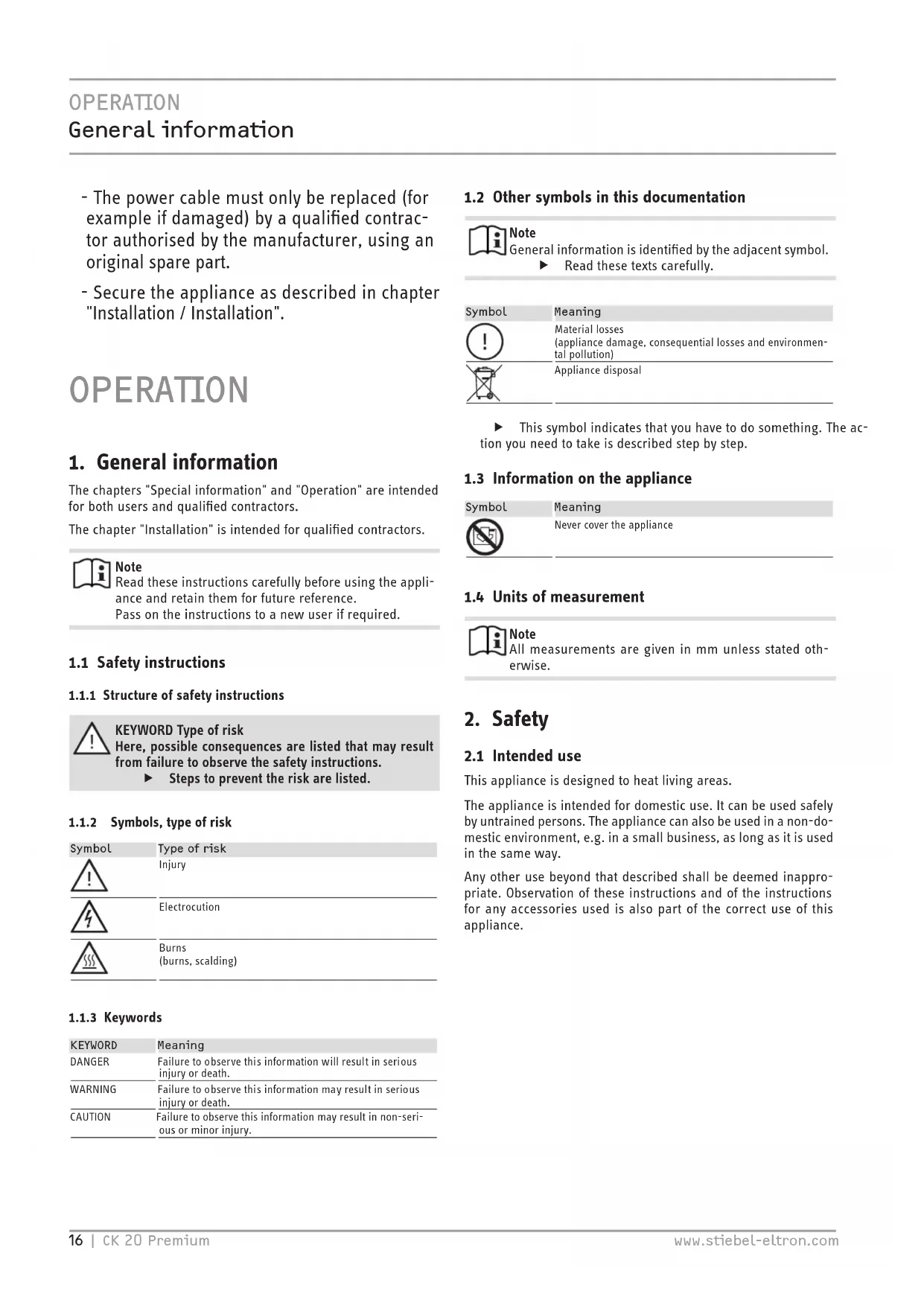
Line drawing of a rectangular electronic device with a control panel and ventilation slots (no text or symbols)BESONDERE HINWEISE
BEDIENUNG
- General information 16
1.1 Safety instructions 16
1.2 Other symbols in this documentation 16
1.3 Information on the appliance ____ 16
1.4 Units of measurement 16 - Safety 16
2.1 Intended use 16
2.2 General safety instructions 17
2.3 Test symbols 17 - Appliance description 17
- Operation 17
4.1 Programming unit 18
4.2 Switching the appliance on and off 18
4.3 Standby mode 19 - Settings 19
5.1 Operating lock 19
5.2 Standard display 19
5.3 Standard menu 19
5.4 Configuration menu 20 - Cleaning, care and maintenance 21
- Troubleshooting 21
INSTALLATION
- Safety 22
8.1 General safety instructions 22
8.2 Instructions, standards and regulations 22 - Appliance description 22
9.1 Standard delivery 22 - Installation 22
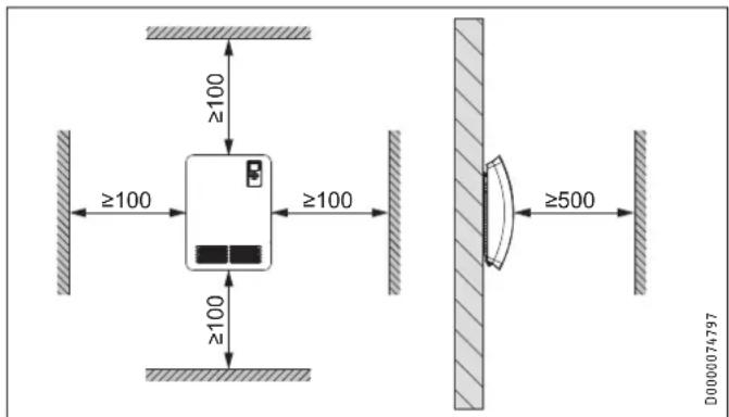
10.1 Minimum clearances 22
10.2 Installing the wall mounting bracket 22
10.3 Appliance installation 23
10.4 Removing the appliance 23
10.5 Electrical connection 23 - Commissioning 23
- Troubleshooting 23
- Appliance handover 24
- Specification 24
14.1 Dimensions and connections 24
14.2 Energy consumption data 24
14.3 Data table 24
GUARANTEE
ENVIRONMENT AND RECYCLING
SPECIAL INFORMATION
- Keep children under the age of 3 away from the appliance if constant supervision cannot be guaranteed.
- Children from the age of 3 to 7 may switch the appliance on and off, provided they are supervised or have been instructed in the safe operation of the appliance and understand any risks that may result. This is subject to the appliance having been installed as described. Children from the age of 3 to 7 must not plug the power cable into its socket or regulate the appliance.
- The appliance may be used by children aged 8 and older and persons with reduced physical, sensory or mental capabilities or a lack of experience and know-how, provided that they are supervised or they have been instructed on how to use the appliance safely and have understood the potential risks.
- Children must never play with the appliance. Children must never clean the appliance or perform user maintenance unless they are supervised.
- Parts of the appliance can get very hot and may cause burns. Particular caution is advised when children or vulnerable persons are present.
- To prevent the appliance from overheating, never cover it with anything.
- Never install the appliance directly below a wall socket.
- In the case of a permanent connection, ensure the appliance can be separated from the power supply by an isolator that disconnects all poles with at least 3 mm contact separation.
- The power cable must only be replaced (for example if damaged) by a qualified contractor authorised by the manufacturer, using an original spare part.
- Secure the appliance as described in chapter "Installation / Installation".
OPERATION
1. General information
The chapters "Special information" and "Operation" are intended for both users and qualified contractors.
The chapter "Installation" is intended for qualified contractors.

Note
Read these instructions carefully before using the appliance and retain them for future reference.
Pass on the instructions to a new user if required.
1.1 Safety instructions
1.1.1 Structure of safety instructions

KEYWORD Type of risk
Here, possible consequences are listed that may result from failure to observe the safety instructions.
▶ Steps to prevent the risk are listed.
1.1.2 Symbols, type of risk
| Symbol | Type of risk |
| Injury | |
| Electrocution | |
| Burns(burns, scalding) |
1.1.3 Keywords
| KEYWORD | Meaning |
| DANGER | Failure to observe this information will result in serious injury or death. |
| WARNING | Failure to observe this information may result in serious injury or death. |
| CAUTION | Failure to observe this information may result in non-serious or minor injury. |
1.2 Other symbols in this documentation

Note
General information is identified by the adjacent symbol.
▶ Read these texts carefully.
| Symbol | Meaning |
| Material losses(appliance damage, consequential losses and environmental pollution) | |
| Appliance disposal |
This symbol indicates that you have to do something. The action you need to take is described step by step.
1.3 Information on the appliance
| Symbol | Meaning |
 | Never cover the appliance |
1.4 Units of measurement

Note
All measurements are given in mm unless stated otherwise.
2. Safety
2.1 Intended use
This appliance is designed to heat living areas.
The appliance is intended for domestic use. It can be used safely by untrained persons. The appliance can also be used in a non-domestic environment, e.g. in a small business, as long as it is used in the same way.
Any other use beyond that described shall be deemed inappropriate. Observation of these instructions and of the instructions for any accessories used is also part of the correct use of this appliance.
2.2 General safety instructions

WARNING Injury
- Keep children under the age of 3 away from the appliance if constant supervision cannot be guaranteed.
- Children from the age of 3 to 7 may switch the appliance on and off, provided they are supervised or have been instructed in the safe operation of the appliance and understand any risks that may result. This is subject to the appliance having been installed as described. Children from the age of 3 to 7 must not plug the power cable into its socket or regulate the appliance.
- The appliance may be used by children aged 8 and older and persons with reduced physical, sensory or mental capabilities or a lack of experience and know-how, provided that they are supervised or they have been instructed on how to use the appliance safely and have understood the potential risks.
- Children must never play with the appliance. Children must never clean the appliance or perform user maintenance unless they are supervised.

WARNING Injury
In closed rooms, temperatures can rapidly reach high levels. Ensure constant supervision if the appliance is operated in a small room and the persons within that room cannot regulate the appliance or leave the room on their own.

WARNING Burns
Never operate this appliance...
- if the distance from adjacent objects or other flammable materials (e.g. furniture, textiles) would be less than the minimum permissible distance.
- in rooms where it is at risk of fire or explosion as a result of chemicals, dust, gases or vapours. Venti-late the room sufficiently before heating.
- in the direct proximity of pipes or receptacles that carry or contain flammable or explosive materials.
- if an appliance component is damaged, the appliance has fallen over or there is a fault.

WARNING Burns
- Never place any flammable, combustible or insulating objects or materials on the appliance or in direct proximity to it.
- Ensure that the air intake and discharge are never blocked.
- Never place any objects between the appliance and the wall.

CAUTION Burns
Parts of the appliance can get very hot and may cause burns. Particular caution is advised when children or vulnerable persons are present.

WARNING Overheating
To prevent the appliance from overheating, never cover it with anything.

Material losses
- Ensure that the power cable is not touching the appliance.
- Never stand on the appliance.
- Never operate the appliance in the open air.
2.3 Test symbols
See type plate on the appliance.
3. Appliance description
The appliance is a wall mounted electric direct heater for areas such as workspaces, kitchens, bathrooms and similar.
The quiet fan draws in the indoor air that is heated by a bare wire heater element. The air then exits evenly through the hot air channel and the air discharge grille set into the bottom of the appliance.
When the set room temperature is reached, it is maintained by periodic heating.
Overheating protection
The appliance is equipped with a high limit safety cut-out that switches the appliance off in case it overheats. Once the cause of the fault has been eliminated, the appliance restarts within a few minutes (cooling period).
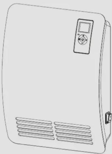
4. Operation
1 Programming unit
2 ON/OFF switch
3 Air discharge
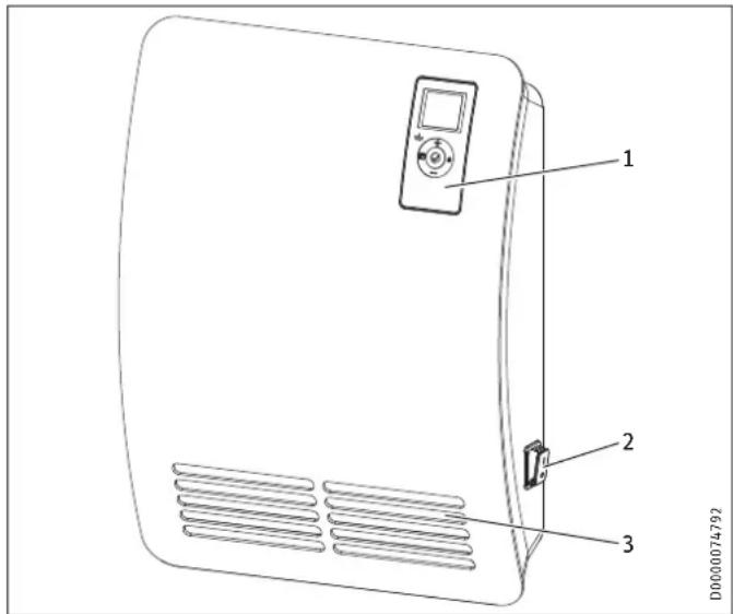
4.1 Programming unit
The appliance is operated using the programming unit which is located at the top right of the appliance front.
1 Display
2 User interface
3 Silent mode indicator with 1000 W heating stage
4.1.1 User interface
| Button Designation Description | ||
 | "Standby" button | Switch on the programming unit;Put programming unit and heating appliance into standby mode |
 | "OK" button | Selection;Confirm settings |
| [2005] | "Menu" button | Call up and exit menu |
 | "+" button | Call up menu items;Change settings |
| [202D]utton | Call up menu items; | Change settings |
4.1.2 Display
If no user action occurs for 20 seconds, the backlighting switches off. Press any button to switch the background lighting on again.
Symbols
| Symbol Description | |
| Time display:Indication of the current time or a programmed start time | |
| Time program activated:The appliance heats in accordance with the enabled time pro-gram. | |
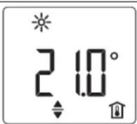
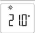
| Comfort mode:The appliance maintains the set comfort temperature.Standard setting: 21.0 °C. Use this setting for comfortable room temperatures when someone is present. | |
| Symbol Description | |
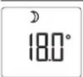
| Setback mode:The appliance maintains the selected setback temperature.Standard setting: 18.0 °C. Use this setting e.g. at night or when absent for several hours. | |
| Frost protection:The frost protection symbol is displayed if the set room temperature is set to 7.0 °C.Use this setting to protect an unused room from frost damage. | |
| Adaptive start:With a time program activated, the heating appliance switching times are adjusted to ensure that the appropriate set room temperature is already reached by the programmed start time.Conditions: The "Adaptive start" function is enabled (see chapter "Settings / Standard menu"). | |
| Window open detection:To avoid unnecessary energy consumption while venting, the appliance automatically switches to frost protection mode for one hour if a window is opened. The "window open detection" symbol flashes. After venting, frost protection mode can be terminated manually by pressing "+" or "OK". The appliance then heats to the set room temperature again.Conditions: Window open detection is enabled (see chapter "Settings / Standard menu"). | |
| Operating lock:The user interface is locked. | |
| Heating enabled:The appliance is heating to maintain the set room temperature. | |
| Room temperature display | |
| Editable parameter:The parameter shown can be changed using "+" and "-" . | |
| Days the week:1 = Monday, 2 = Tuesday ... 7 = Sunday | |
4.2 Switching the appliance on and off

Note
For a short time after initial start-up and after longer breaks in use, a smell may develop briefly.
The appliance is ready for operation as soon as it has been fixed to the wall and plugged into the mains.
▶ Switch the appliance on or off using the ON/OFF switch on the right-hand side of the appliance.
▶ Switch the appliance off when not in use for longer periods (e.g. during the summer months).
All settings remain intact after switching off or after an interruption to the power supply. This appliance is equipped with a power reserve that ensures the day of the week and the time are saved for several hours.

Note
If the appliance has been switched off for a longer time with a time program activated, you will be prompted to set the day and time after switching it back on. Until this setting is made, the appliance will operate in comfort mode.
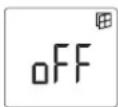
4.3 Standby mode

Material losses
In standby mode, the appliance will not switch on heating under any circumstances. There will be no frost protection.
▶ To switch on the programming unit, press "Standby". The standard display appears.
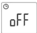
▶ To put the programming unit and the heating appliance into standby mode, press "Standby". The display shows "----".
5. Settings
5.1 Operating lock
To lock or unlock the user interface, press and hold "+" and "-" simultaneously for 5 seconds.
5.2 Standard display
D0000075500
The standard display is continuously displayed. If no user action is performed for longer than 20 seconds while in the menu, the device automatically switches to the standard display.
The default display shows the current set room temperature as well as the "Editable parameter" symbol. You can use "+" and "-" to change the set room temperature.
If the set room temperature corresponds to one of the values set for the comfort or setback temperature, the symbol for the corresponding operating mode (comfort mode, setback mode) appears in the menu bar.
The set room temperature can also be changed manually with a time program activated. The changed set room temperature is maintained until the next programmed switching point is reached.
5.3 Standard menu
To access the standard menu, briefly press "Menu". You can now call up the following menu items:
Display Description

Select day of the week and time
Select comfort temperature
The comfort temperature must be set at least 0.5 °C higher than the setback temperature.
Select setback temperature
Display Description
Switch "Window open detection" function on and off
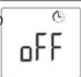
Select time program (Pro1, Pro2, Pro3, Pro4) or deactivate (off)
Switch "Adaptive start" function on and off
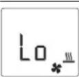
Set silent mode
Lo = quiet 1000 W base heating stage
Hi = powerful 2000 W rapid heating stage
To change the setting of a menu item, call the relevant menu item up using "+" and "-" . Press "OK".
As soon as the "Editable parameter" symbol appears, you can change the setting of the menu item with "+" and "-". Press "OK" to save the setting.
To exit the standard menu, press "Menu". The standard display appears.
5.3.1 120-minute short-time timer
With the 120-minute short-time timer, you can activate comfort mode for a selected time of up to 120 minutes. During this selected time, the appliance heats to the set comfort temperature. After this, the appliance operates in setback mode.
If you wish to use the 120-minute short-time timer, select time program Pro4 from the standard menu.
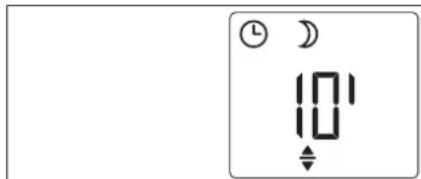
D0000075531
The standard display shows the selected time in minutes as well as the "Editable parameter" symbol. Using the "+" and "-" buttons, you can select any length of time from 10 - 120 minutes.
To activate the short-time timer, press "OK". The appliance switches to comfort mode until the end of the selected time. The minute display flashes during this period.
If you wish to stop the short-time timer, press and hold "OK" for longer than 3 seconds.
At the end of the selected time, the appliance automatically reverts to setback mode.
5.3.2 Silent mode
You can choose between the following two heating outputs with matched fan speed:
Base heating stage
Set "Lo" in the standard menu for silent mode. The appliance heats with a heating output of 1000 W and reduced fan speed. The LED on the programming unit illuminates green.

Note
Do not operate the appliance at the base heating stage if the room where it is installed has cooled down significantly.
▶ If the room has cooled down significantly, switch appliance to the rapid heating stage in order to ensure normal appliance operation.
Rapid heating stage
Set "Hi" in the standard menu for silent mode. The appliance heats with a heating output of 2000 W and fast fan speed.
Select the powerful rapid heating stage if you need to heat up a cold room rapidly to the selected temperature. Then set the base heating stage again.
When the selected room temperature has been reached, it is maintained by the appliance through periodic heating.
5.4 Configuration menu
Display Description
| I1-I2 Actual values |
| Pro1-Pro3 Time programs |
| P1-P5 Parameter |
In the configuration menu, you can call up actual values, set time programs and adjust parameters.
To access the configuration menu, press and hold "Menu". After approx. 3 seconds, actual value I1 is displayed.
Use "+" and "-" to switch between the individual actual values, time programs and parameters.
To exit the configuration menu, press "Menu". The standard display appears.
5.4.1 Actual values
The following actual values can be called up:
| Display Description Unit | ||
| I1 | Actual room temperature | [°C] | [°F] |
| I2 | Relative heating time(The counter can be reset via parameter P5.) | [h] |

Note
The counter for relative heating time (12) counts in complete hours how long the appliance heats for. When the appliance is switched off, any heating phase of less than 60 minutes is not recorded.
5.4.2 Time programs
Three time programs are available. Time programs Pro1 and Pro2 are pre-configured at the factory. Time program Pro3 can be set according to your individual requirements.
Display Description
| Pro1 | Time program "Daily"- Repeated: Monday to Sunday |
| Pro2 | Time program "Weekdays"- Repeated: Monday to Friday |
| Pro3 | Time program "User defined"- up to 14 comfort phases, freely configurable |

Note
To use a time program, select the required time program from the standard menu (see chapter "Settings / Standard menu").

Note
Ensure the day of the week and the time are set correctly when setting the time programs.

Note
The following applies to all time programs (Pro1, Pro2, Pro3):
If the end time is later than 23:59 h, the end time will automatically be moved to the next day of the week. The comfort phase is maintained past midnight and will end on the next day at the set end time.
Time programs Pro1 and Pro2
You can specify the comfort mode start and end times with time programs Pro1 and Pro2. During this time period, the appliance heats to the set comfort temperature. Outside this specified time period, the appliance operates in setback mode. This results in a comfort phase and a setback phase, which are repeated daily (Pro1) or on every working day (Pro2).
Theses phases are factory-set as follows:
- 08:00 h - 22:00 h: Comfort mode
- 22:00 h - 08:00 h: Setback mode

Note
When time program Pro2 is enabled, the appliance operates at weekends exclusively in setback mode.
To adapt time programs Pro1 and Pro2 according to your needs, proceed as follows:
▶ In the configuration menu, use "+" and "-" to call up the required time program.
▶ Press "OK".
The start time for comfort mode is displayed.
▶ Use "+" and "-" to set the required start time.
▶ Press "OK".
The end time for comfort mode is displayed.
▶ Use "+" and "-" to set the required end time.
▶ Press "OK" to save.
Time program Pro3
You can use time program Pro3 to specify up to 14 separate comfort phases which are repeated weekly.
To configure a comfort phase in time program Pro3, proceed as follows:
▶ In the configuration menu, use "+" and "-" to call up time program Pro3.
▶ Press "OK".
The display shows "3---".
▶ Press "OK".
A day of the week or a group of days is displayed.
▶ Use "+" and "-" to select the required day or group of days.
▶ Press "OK".
The start time for comfort mode is displayed.
▶ Use "+" and "-" to set the required start time.
▶ Press "OK".
The end time for comfort mode is displayed.
▶ Use "+" and "-" to set the required end time.
▶ Press "OK".
Comfort phase "3-01" has been configured.
▶ To configure a further comfort phase, use "+" and "-" in time program Pro3 to select display "3---". Proceed as describe above.

Note
To reset the selected comfort phases, activate parameter P4.
▶ Please note that activating parameter P4 resets all time programs (Pro1, Pro2, Pro3) to the factory setting.
5.4.3 Parameter
You can call up the following parameters:
| Display Description Options | ||
| P1 Room temperature offset ± 3 °C | ± 5 °F | ||
| P2 Time format 12 h | 24 h | ||
| P3 Temperature display units °C | °F | ||
| P4 Reset the time programs (Pro1, Pro2, Pro3) on | off | ||
| P5 | Reset relative heating time | on | off |
To change the value of a parameter, use "+" and "-" to call up the relevant parameter. Press "OK".
As soon as the "Editable parameter" symbol appears, you can change the parameter value with "+" and "-". Press "OK" to save the selected value.
P1: Room temperature offset
Uneven temperature distribution in the room can result in a difference between displayed actual temperature l1 and the room temperature you measure. To compensate for this difference, a room temperature offset of ±3 ^ can be set via parameter P1.
Example: The appliance indicates I1 = 21.0 °C. You have measured a room temperature of 20.0 °C. There is a difference of 1.0 °C.
▶ To compensate for the difference, select an offset of P1 = -1.0.
P2: Time format
Parameter P2 allows you to specify whether the time is displayed in the 12 hour or 24 hour format.
P3: Temperature display units
Parameter P3 is used to specify whether the room temperature is displayed in degrees Centigrade [°C] or Fahrenheit [°F].
P4: Reset time programs
Activating parameter P4 resets all time programs (Pro1, Pro2, Pro3) to the factory setting.
P5: Reset relative heating time
Activating parameter P5 resets the counter for relative heating time (I2).
6. Cleaning, care and maintenance
The appliance contains no user serviceable parts.

Material losses
- Never spray cleaning spray into the air slot.
-
Ensure that no moisture can enter the appliance.
-
If a pale brownish discolouration appears on the appliance casing, wipe it off with a damp cloth.
- Clean the appliance when cold with ordinary cleaning products. Avoid abrasive or corrosive cleaning products.
7. Troubleshooting
| Problem | Cause | Remedy |
| Room does not get warm enough. Ap- pliance does not get hot. | Temperature set too low on the appliance. | Check the temperature set on the appliance. Adjust if necessary. |
| No power supply. | Check position of the ON/OFF switch, RCD and fuse/MCB in your fuse box. | |
| Room does not get warm enough al- though the appliance is hot. | Overheating. High limit safety cut-out limits heating output. | Eliminate the cause (dirt or obstructions at the air intake or discharge). Observe mini-mum clearances. |
| Heat demand of the room is higher than the appli- ance output. | Remedy heat losses (Close windows and doors. Avoid constant venting.) | |
| The room gets too hot. | Appliance temperature is set too high. | Check the selected room temperature. Adjust if nec- essary. |
| Window open de- tection does not respond. | Appliance does not detect a pronounced tempera- ture drop when venting. (Window open detection requires a previously sta- ble room temperature.) | Wait a while after making settings on the appliance, until the room temperature has fully stabilised. |
| Avoid obstructions to air changes between appliance and indoor air. | ||
| Manually switch the appli- ance to standby mode for the duration of venting. | ||
| .0. | Window open detection is not enabled. | Switch on window open detection in the standard menu. |
| Problem Cause Remedy | ||
| "Adaptive start" function does not work as required. | This function is only effective with a time program activated. | Use the time programs for optimised heating convenience. |
| Severely fluctuating room temperature or the appliance learning procedure has not been completed. | Wait a few days for the behaviour to stabilise. | |
| "Adaptive start" function is not enabled. | Switch on the "Adaptive start" function in the standard menu. | |
| "Err" or "E..." is displayed. | Internal fault detected. | Notify the qualified contractor. |
If you cannot remedy the fault, contact your qualified contractor. To facilitate and speed up your request, provide the number from the type plate (000000-0000-000000).
INSTALLATION
8. Safety
Only a qualified contractor should carry out installation, commissioning, maintenance and repair of the appliance.
8.1 General safety instructions
We guarantee trouble-free function and operational reliability only if original accessories and spare parts intended for the appliance are used.

WARNING Electrocution
When installing the heating appliance in rooms with a bath or shower, observe the safety zone according to VDE 0100, section 701 [or local regulations], in accordance with the details on the appliance type plate.

CAUTION Burns
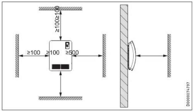
- Only mount the appliance on a vertical wall that is temperature-resistant to at least 85 °C.
- Maintain the minimum clearances to adjacent objects.

Material losses
- If connecting the appliance via a socket, ensure that this is easily accessible once the appliance has been installed.
- Never install the appliance directly below a wall socket.
- Ensure that the power cable is not in contact with any appliance components.
8.2 Instructions, standards and regulations

Note
Observe all applicable national and regional regulations and instructions.
9. Appliance description
9.1 Standard delivery
The following are delivered with the appliance:
- Wall mounting bracket (hooked into the appliance)
10. Installation
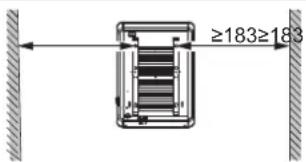
10.1 Minimum clearances
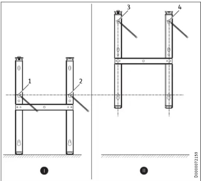
10.2 Installing the wall mounting bracket
The appliance is intended for wall mounting using the wall mounting bracket supplied.

Note
- The wall mounting bracket can be used as a template for wall mounting. This ensures sufficient clearance from the floor.
- Use a spirit level if the floor is uneven or sloping.
D0000074798
▶ Unhook the wall mounting bracket from the appliance.
▶ Place the centred wall mounting bracket horizontally on the floor. Mark holes 1 and 2.
▶ Lift up the wall mounting bracket so that its lower holes match up with the markings you have just made on the installation wall.
▶ Mark holes 3 and 4 on the installation wall.
▶ Drill the holes at the 4 markings.
- Secure the wall mounting bracket with suitable fixing materials (screws, rawl plugs). With the vertical slots, you can compensate for an offset fixing hole.
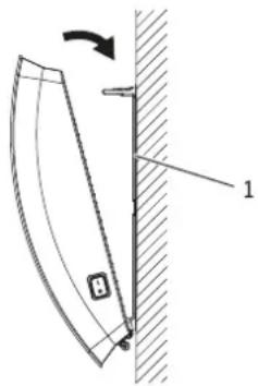
10.3 Appliance installation
D0000074794
1 Wall mounting bracket
▶ Hook the appliance onto the bottom tabs of the wall mounting bracket by the slots in the back of the appliance.
▶ Place the appliance in an upright position.
▶ Secure the appliance by pushing it towards the wall until it audibly snaps into place in the two upper springs on the wall mounting bracket.
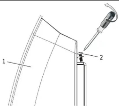
D0000074795
1 Appliance
2 Locking screw
- Secure the appliance against unintentional release using the supplied locking screw on the right or left-hand side of the wall mounting bracket.
10.4 Removing the appliance
▶ Undo and remove the locking screw from the wall mounting bracket.
▶ To release the appliance, push down the springs at the top of the wall mounting bracket.
▶ Tilt the appliance away from the wall and lift it off the bottom tabs on the wall mounting bracket.
10.5 Electrical connection

WARNING Electrocution
- Carry out all electrical connection and installation work in accordance with relevant regulations.
- Do not install the appliance with a fixed power cable.

Material losses
- Observe the type plate. The specified voltage must match the mains voltage.
- Ensure the on-site supply cable has an adequate cross-section.
The appliance is supplied fully wired (with a mains plug), but it is also suitable for permanent connection.
10.5.1 Connection to a standard socket
▶ Plug the appliance into a standard socket.
10.5.2 Permanent connection to an appliance junction box

WARNING Electrocution
In the case of a permanent connection, the appliance must be able to be separated from the power supply by an isolator that disconnects all poles with at least 3 mm contact separation.

Material losses
- Trim the power cable so it leads directly to the appliance connection socket.
-
Ensure that, after trimming the power cable, the appliance can still be removed from the wall without a problem.
-
Trim the power cable by cutting off the plug.
▶ Connect the power cable to a suitable appliance junction box.
11. Commissioning
The appliance is ready for operation as soon as it has been fixed to the installation wall and connected to the mains.
▶ Remove the protective film from the programming unit.
12. Troubleshooting
The power cable must only be replaced (for example if damaged) by a qualified contractor authorised by the manufacturer, using an original spare part.
13. Appliance handover
Explain the functions of the appliance to the user. Draw special attention to the safety instructions. Hand over the operating and installation instructions to the user.
14. Specification
14.1 Dimensions and connections
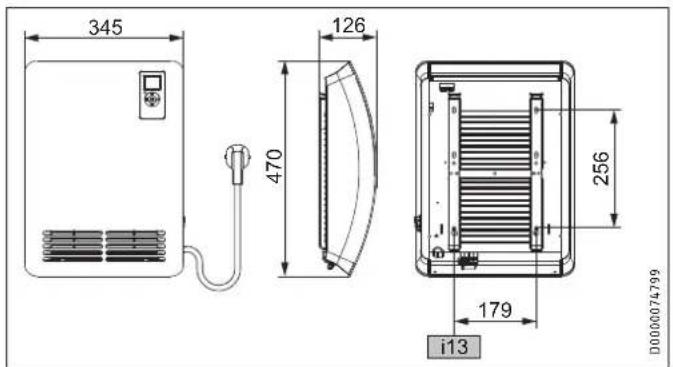
| CK 20 Premium | |
| i13 Wall mounting bracket |
14.2 Energy consumption data
The product data complies with EU regulations relating to the Directive on the ecodesign of energy related products (ErP).
Product information on electric individual room heaters to regulation (EU) 2015/1188
| CK 20 | Premium | |
| 237835 | ||
| Manufacturer STIEBEL | ELTRON | |
| Heating output | ||
| Rated heating output P_nom | kW 2.0 | |
| Minimum heating output (standard value) P_min | kW 0.0 | |
| Maximum continuous heating output P_max,c | kW 2.0 | |
| Auxiliary power consumption | ||
| At rated heating output el _max | kW | 0.000 |
| At minimum heating output el _min | kW | 0.000 |
| In standby el _SB | kW | 0.000 |
| Type of heating output/room temperature control | ||
| Single stage heating output, no room temperature control | - | |
| Two or more manually selectable stages, no room temperature control | - | |
| Room temperature control with mechanical thermostat | - | |
| With electronic room temperature control | - | |
| Electronic room temperature control and time of day control | - | |
| Electronic room temperature control and day of week control | x | |
| Other control options | ||
| Room temperature control with motion detection | - | |
| Room temperature control with window open detection | x | |
| With remote control option | - | |
| With adaptive control of heating start | x | |
| With operating time limitation | - | |
| With black bulb sensor | - | |
14.3 Data table
| CK 20 Premium | ||
| 237835 | ||
| Electrical data | ||
| Connected load | W | 2000 |
| Power supply | 1/N/PE ~ 230 V | |
| Rated current | A | 8.7 |
| Frequency | Hz | 50/- |
| Energy data | ||
| Room heating seasonal efficiency _s | % | 39 |
| Dimensions | ||
| Height | mm | 470 |
| Width | mm | 345 |
| Depth | mm | 126 |
| Weights | ||
| Weight | kg | 5.3 |
| Versions | ||
| Version | Wall mounted unit | |
| Frost protection setting | °C | 7 |
| IP rating | IP 24 | |
| Protection class | 1 | |
| Colour | Alpine white | |
| Values | ||
| Output stages | 2 | |
| Setting range | °C | 5 - 30 |
| Operating noise | dB(A) | 48 |
Guarantee
The guarantee conditions of our German companies do not apply to appliances acquired outside of Germany. In countries where our subsidiaries sell our products a guarantee can only be issued by those subsidiaries. Such guarantee is only granted if the subsidiary has issued its own terms of guarantee. No other guarantee will be granted.
We shall not provide any guarantee for appliances acquired in countries where we have no subsidiary to sell our products. This will not affect warranties issued by any importers.
Environment and recycling
We would ask you to help protect the environment. After use, dispose of the various materials in accordance with national regulations.
REMARQUES PARTICULIÈRES
UTILISATION
10.1 Distances minimales
10.2 Montage du support mural
CK 20 Premium
i13 Support mural
WAARSCHUWING verbranding
WAARSCHUWING oververhitting
D0000074794
1 Nástěnný držák
6 Prohasky Street | Port Melbourne VIC 3207
Tel. 03 9645-1833 | Fax 03 9645-4366
info@stiebel.com.au
www.stiebel.com.au
Austria
STIEBEL ELTRON Ges.m.b.H.
Plant C3, XEDA International Industry City
Xiqing Economic Development Area
300085 Tianjin
Tel. 022 8396 2077 | Fax 022 8396 2075
info@stiebeleltron.cn
www.stiebeleltron.cn
Czech Republic
STIEBEL ELTRON spol. s r.o.
K Hájüm 946 | 155 00 Praha 5 - Stodülky
Tel. 251116-111 | Fax 235512-122
Urzhumskaya street 4,
building 2 | 129343 Moscow
Tel. 0495 7753889 | Fax 0495 7753887
info@stiebel-eltron.ru
www.stiebel-eltron.ru
Slovakia
TATRAMAT - ohrievače vody s.r.o.
Hlavná 1 | 058 01 Poprad
Tel. 052 7127-125 | Fax 052 7127-148
info@stiebel-eltron.sk
www.stiebel-eltron.sk
Switzerland
STIEBEL ELTRON AG
Industrie West
Gass 8 | 5242 Lupfig
Tel. 056 4640-500 | Fax 056 4640-501
info@stiebel-eltron.ch
www.stiebel-eltron.ch
Thailand
STIEBEL ELTRON Asia Ltd.
469 Moo 2 Tambol Klong-Jik
Amphur Bangpa-In | 13160 Ayutthaya
Tel. 035 220088|Fax 035 221188
info@stiebeleltronasia.com
www.stiebeleltronasia.com
United Kingdom and Ireland
STIEBEL ELTRON UK Ltd.
Unit 12 Stadium Court
Stadium Road | CH62 3RP Bromborough
Tel. 0151 346-2300 | Fax 0151 334-2913
info@stiebel-eltron.co.uk
www.stiebel-eltron.co.uk
United States of America
STIEBEL ELTRON, Inc.
17 West Street | 01088 West Hatfield MA
Tel. 0413 247-3380 | Fax 0413 247-3369
info@stiebel-eltron-usa.com
www.stiebel-eltron-usa.com

Irrtum und technische Änderungen vorbehalten! | Subject to errors and technical changes! | Sous réserve d'erreurs et de modifications techniques! | Onder voorbehoud van vergissingen en technische wijzigingen! | Salvo error o modificación técnica! | Excepto erro ou alteração técnica | Zastrzeżone zmiany techniczne i ewentualne błędy | Omyly a technické zmény jsou vyhrazeny! | A muszaki változtalások és têvedések jogát fenntartjuk! | Otcytствие ошибok ne гарантируется. Возможны технические изменения. | Chyby a technické zmény sű vyhradené! Stand 9375
STIEBEL ELTRON

- BESONDERE HINWEISE
- BEDIENUNG
- INSTALLATION
- GUARANTEE
- ENVIRONMENT AND RECYCLING
- SPECIAL INFORMATION
- OPERATION
- General information
- Note
- Safety instructions
- Structure of safety instructions
- KEYWORD Type of risk
- Symbols, type of risk
- Keywords
- Other symbols in this documentation
- Information on the appliance
- Units of measurement
- Safety
- Intended use
- General safety instructions
- WARNING Injury
- WARNING Burns
- CAUTION Burns
- WARNING Overheating
- Material losses
- Test symbols
- Appliance description
- Overheating protection
- Operation
- Programming unit
- Display
- Switching the appliance on and off
- Standby mode
- Settings
- Operating lock
- Standard display
- Standard menu
- 120-minute short-time timer
- Silent mode
- Base heating stage
- Rapid heating stage
- Configuration menu
- Actual values
- Time programs
- Time programs Pro1 and Pro2
- Time program Pro3
- Parameter
- P1: Room temperature offset
- P2: Time format
- P3: Temperature display units
- P4: Reset time programs
- P5: Reset relative heating time
- Cleaning, care and maintenance
- Troubleshooting
- Safety
- General safety instructions
- WARNING Electrocution
- Instructions, standards and regulations
- Appliance description
- Standard delivery
- Installation
- Minimum clearances
- Installing the wall mounting bracket
- Appliance installation
- Wall mounting bracket
- Removing the appliance
- Electrical connection
- Connection to a standard socket
- Permanent connection to an appliance junction box
- Commissioning
- Troubleshooting
- Appliance handover
- Specification
- Energy consumption data
- REMARQUES PARTICULIÈRES
- UTILISATION
- Distances minimales
- Montage du support mural
- WAARSCHUWING verbranding
- WAARSCHUWING oververhitting
- Nástěnný držák
- Austria
- Czech Republic
- Slovakia
- Switzerland
- Thailand
- United Kingdom and Ireland
- United States of America
Brand : STIEBEL ELTRON
Model : CK 20 Premium
Category : Heating