99448 - Multimeter Brüder Mannesmann - Free user manual and instructions
Find the device manual for free 99448 Brüder Mannesmann in PDF.
| Product type | Digital multimeter |
| Brand | Brüder Mannesmann |
| Model | 99448 |
| Display | LCD 3 1/2 digits, digit size 20 mm |
| Auto polarity | Yes |
| Low battery indicator | Symbol displayed |
| Overload indicator | "OL" |
| Operating temperature | 0°C to 40°C, relative humidity < 75% |
| Storage temperature | -10°C to +50°C |
| Power supply | 9 V block battery (6F22) |
| Fuse F1 | 250 mA / 300 V fast-acting |
| Fuse F2 | 10 A / 300 V fast-acting |
| Measurement category | CAT III (300 V) |
| Pollution degree | 2 |
| DC voltage | 200 mV, 2 V, 20 V, 200 V, 300 V |
| AC voltage | 2 V, 20 V, 200 V, 300 V |
| DC current | 200 µA, 2 mA, 20 mA, 200 mA, 10 A |
| AC current | 2 mA, 20 mA, 200 mA, 10 A |
| Resistance | 200 Ω, 2 kΩ, 20 kΩ, 200 kΩ, 2 MΩ, 20 MΩ |
| Diode test | Yes (open circuit voltage 2.9 V) |
| Battery test | 1.5 V and 9 V |
| Continuity test | Yes (buzzer for resistance < 20 Ω) |
| HOLD button | Yes (holds measured value) |
| Warranty | 2 years |
| Cleaning | Dust brush or slightly damp soft cloth (no solvents) |
| Battery replacement | Yes (9V block battery) |
| Fuse replacement | Yes (F1 and F2) |
Frequently Asked Questions - 99448 Brüder Mannesmann
User questions about 99448 Brüder Mannesmann
0 question about this device. Answer the ones you know or ask your own.
Ask a new question about this device
Download the instructions for your Multimeter in PDF format for free! Find your manual 99448 - Brüder Mannesmann and take your electronic device back in hand. On this page are published all the documents necessary for the use of your device. 99448 by Brüder Mannesmann.
USER MANUAL 99448 Brüder Mannesmann
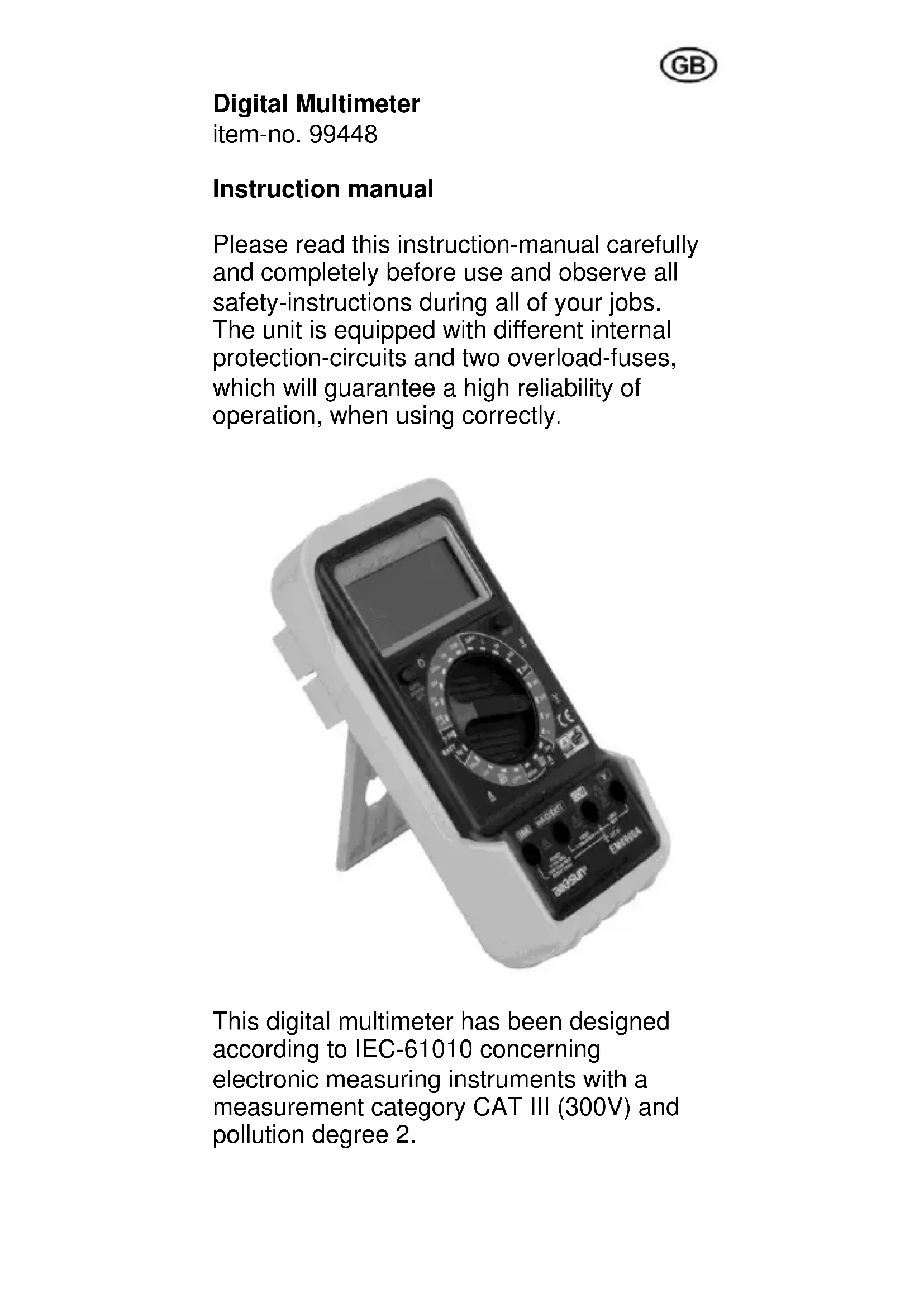
Please read this instruction-manual carefully and completely before use and observe all safety-instructions during all of your jobs. The unit is equipped with different internal protection-circuits and two overload-fuses, which will guarantee a high reliability of operation, when using correctly.
This digital multimeter has been designed according to IEC-61010 concerning electronic measuring instruments with a measurement category CAT III (300V) and pollution degree 2.
General specifications
- 3 1/2-digit LCD-display, figure-size 20 mm
- automatic polarity-indicator
- low battery-indicator
- overload-indicator "OL"
working-temperature 0^ - 40^, rel. humidity < 75% - storing-temperature -10^ - + 50^ C
- battery: 9 V battery (6F22)
- fine-wire fuses:
- F1: quick-acting 250mA / 300V - F2: quick-acting 10A / 300V
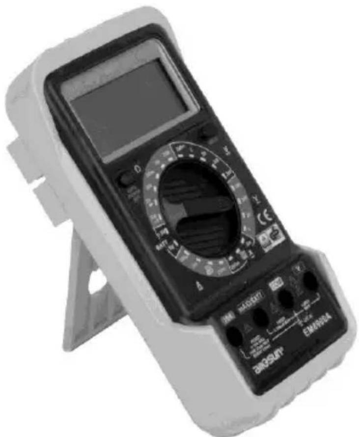
Discription of the instrument
- power switch
- LCD-display
- Hold-button to enter/exit data-hold-mode
- positive (+) input for voltage measurements
- negative (-) input "COM" for all ranges
- positive (+) input mA/Ω/BATT for all ranges besides all voltage measurements and current measurements exceeding 200 mA
- positive (+) input 10 A for the 10A-range
- function/range switch
Safety instructions
In order to protect the multimeter against damage and to guarantee a safe measurement, the user has to observe the following safety-instructions and to follow the current VDE-regulations:
-
Check the measuring-instrument and the measuring-cables before each use. A defect instrument or cable must not be used any longer.
-
In case of any damage the instrument may be opened and repaired exceptionally by authorized and competent specialists.
-
Check the function of the instrument before each use by testing a known currency.
-
Be sure not to exceed the limiting values, printed beside the entry-hubs on the instrument and written in the technical specifications.
-
In order to avoid electric accidents, the voltage between "COM"-hub and the ground must never exceed the value of 300 volts.
-
Only use the instrument with completely closed housing.
-
Only use the measuring-cables, which are included in the packing.
Always put the plugs of the measuring-cable completely into the hubs.
-
Position the central-switch to the adequate measuring-position and -range, before starting your job.
-
If the expected measured value is unknown, you have to start by using the highest range and then to reduce the range, in order to achieve a proper test-reading.
-
Touch and hold the test prod only at the insulated plastic-parts above the finger-guard. Do not touch the metal-parts of the test prod with your fingers.
GB
Pay special attention, when measuring currency of: Direct current (DCV / =) over 60V Alternating current (ACV / ) over 30V
-
Do not touch any grounded parts during measuring (pipes, radiators, etc.)
-
When measuring resistors or diodes, no external voltage may reach the entry-hubs. Before starting your job, disconnect mains-operated units from the power-supply or remove the battery from battery-operated test-objects.
-
Avoid any shocks, influence of humidity and dust and do not expose to the sun. Pay attention not to exceed the max. working-temperature, in order to avoid blackening of the display-background.
-
For cleaning the instrument you may use a clean brush or cloth. (Do not use any cleaning-liquids or solvents!) Do not let any liquids enter the interior of the instrument.
Always switch-off the instrument after having finished your measures.
- Before storing the instrument for a longer period, remove the battery from the instrument (danger of leakage) and store the instrument at a dry and safe place out of the reach of children.
Alternating voltage (ACV / V~)
-
Connect the black cable to "COM"-hub and the red measuring-cable to the "V"-hub.
-
Position the center-switch in the area "V~" to the required range. If the expected measured value is unknown, you have to start by using the highest
range and then to reduce the range, in order to achieve a proper test-reading.
- Place the test prods to the spot mark and the value is shown on the display.
Direct voltage (DCV / V=)
-
Connect the black cable to "COM"-hub and the red measuring-cable to the "V"-hub.
-
Position the center-switch in the area "V=" to the required range. If the expected measured value is unknown, you have to start by using the highest range and then to reduce the range, in order to achieve a proper test-reading.
-
Place the test prods to the spot mark (observe the correct polarity!) and the value is shown on the display.
Alternating current (DCA / A~)
-
Connect the black cable to "COM"-hub and the red measuring-cable either to the" mA/Ω/BATT"-hub (upto 200mA) or to the "10A"-hub (upto 10A).
-
Position the center-switch either in the area "A~" to the required range or to the value "10A".
-
Place the test prods to the spot mark (observe the correct polarity!) and the value and polarity are shown on the display (polarity of the red cable is positive +).
Direct Current (A =)
- Connect the black cable to "COM"-hub and the red measuring-cable either to the" mA/Ω/BATT"-hub (upto 200mA) or to the "10A"-hub (upto 10A).
- Position the center-switch either in the area "A = " to the required range or to the value "10A".
- Place the test prods to the spot mark (observe the correct polarity!) and the value and polarity are shown on the display (polarity of the red cable is positive +).
Resistance measuring
- Attention: Resistance measurement may only be done with idle resistors!
- Connect the black cable to "COM"-hub and the red measuring-cable to the "mA/Ω/BATT"-hub.
- Position the center-switch in the area "Ω" to the required range.
- Place the test prods to the spot marks of the resistor and the value is shown on the display.
Diode testing
- Attention: Diode testing may only be done with idle semiconductor diodes! When testing diodes inside of electric circuits, the operating voltage of the circuit has to be switched off.
- Connect the black cable to "COM"-hub and the red measuring-cable to the"mA/Ω/BATT"-hub.
-
Position the center switch to "
-
Connect the red test prod with the drain (+), the black test prod with the source (-) of the diode.
- The value of the bias-voltage (mV) is shown in the display. In case of wrong polarity, figure "OL" will be shown in the display. Repeat the test with changed poles.
Continuity test
- Connect the black cable to "COM"-hub and the red measuring-cable to the"mA/Q/BATT"-hub.
- Position the center switch to "
- Connect the test leads across the circuit to be tested.
- If the resistance is less than 20 , the built-in buzzer will sound.
Battery test
- Connect the black cable to "COM"-hub and the red measuring-cable to the"mA/Q/BATT"-hub.
- According to the rated voltage of the battery to be tested, set the range switch in the corresponding BATT range position.
- Connect the test leads to the two terminals of the battery to be tested.
- Read the working voltage of the battery on the display.
- In the ranges "BATT 1,5V" and "-9V" the battery to be tested is charged by an internal resistance; so you get practical information on the condition of the tesed battery.
Changing the battery
As soon, as the display shows "the battery has to be changed.
- Switch the multimeter "OFF" and plug-off the test prods.
- Open the backside of the instrument and take out the worn-out battery.
- Remove the push-button connection from the worn-out battery and fasten on the new battery (9V-Block / 6F22).
- Place the new battery into the housing and close the backside of the instrument securely.
Attention: According to the battery-regulations you have to dispose defect or worn-out batteries through your local trade or through national battery-collecting systems.
Contravention will be punished as infringement by fine.
Changing the fuse
- In case the fuse is blown due to overload or operating error, open the backside of the multimeter, take out the battery and remove the push-button connector.
- Remove the defect fuse and replace by a new one of the same type.
- The unit contains two fuses: F1: 250 mA/300 V F F2: 10 A/300 V F
2 years warranty
The warranty-period begins at the date of purchase. Please include your original receipt when sending the unit for repair.
During the warranty period, the following points are covered:
- no charge for remedy of defects
- no charge for replacement of faulty parts
- including free qualified engineer service (i.e. repair by qualified technicians)
All of the above are based upon the fact that damages are not due to improper treatment.
In the event that you should have any questions or quality problems, please contact the manufacturer directly:
Old tools and protection of the environment
In the event that your tool has been used so much that it has to be replaced, or whenever you have no further use for it, please consider the environment. Electrical equipment does not belong with your regular
rubbish. Instead, it must be disposed through your central recycling-point for electrical and electronic appliances.
Technical specifications
| Function Range Resolution Accuracy | Overload-prot. | |||
| Direct voltage V DC | 200 mV 0,1 mV ± (0,5% + 5) | 300 V DC/AC | ||
| 2 V 1 mV | ± (0,8% + 5) | |||
| 20 V 10 mV | ||||
| 200 V 0,1 V | ||||
| 300 V 1 V ± (1,0% + 5) | ||||
| Alternating voltage V AC | 2 V 1 mV | ± (1,0% + 5) | 300 V AC/DC | |
| 20 V 10 mV | ||||
| 200 V 0,1 V | ||||
| 300 V 1 V ± (1,2% + 5) | ||||
| Direct current A DC | 200 μA 0,1 μA | ± (1,0% + 5) | 250 mA/300V F | |
| 2 mA 1 μA | ||||
| 20 mA 10 μA | ± (1,2% + 5) | |||
| 200 mA 0,1 mA | ||||
| 10 A 10 mA ± (2,0% + 5) | 10 A/300V F | |||
| Alternating current A AC | 2 mA 1 μA ± (1,2% + 5) | 250 mA/300V F | ||
| 20 mA 10 μA | ± (1,5% + 5) | |||
| 200 mA 0,1 mA | ||||
| 10 A 10 mA ± (3,0% + 7) | 10 A/300V F | |||
| Resistor | 200 Ω | 0,1 Ω | ± (1,0% + 5) | 300 V DC/AC |
| 2 kΩ | 1 Ω | ± (0,8% + 3) | ||
| 20 kΩ 10 Ω | ||||
| 200 kΩ | 0,1 kΩ | |||
| 2 MΩ | 1 kΩ | |||
| 20 MΩ | 10 kΩ | ± (1,2% + 3) | ||
| Diode test | 1 mV | Test current 1,0 mA, open circuit voltage 2,9 V | ||
| Battery test | 1,5 V | working current approx. 20 mA | ||
| 9 V | working current approx. 5 mA | |||
Multimetro digital
No. de Articulo 99448