GXDL52H1 - Monitor SONY - Free user manual and instructions
Find the device manual for free GXDL52H1 SONY in PDF.
| Product type | Monitor |
| Resolution | 1920 x 1080 pixels (Full HD) |
| Screen size | 21.5 inches |
| Display technology | LED |
| Response time | 5 ms |
| Viewing angle | 178° horizontal and vertical |
| Connectivity | HDMI, VGA |
| Power consumption | 25 W (operating) |
| Dimensions (without stand) | 48.5 x 28.5 x 4.5 cm |
| Country of manufacture | Japan |
| Warranty | 2 years |
| Recommended use | Office, gaming, multimedia |
| Maintenance | Clean with a soft cloth, avoid harsh chemicals |
| Safety | Complies with CE standards, do not expose to moisture |
| Included accessories | Power cable, HDMI cable |
Frequently Asked Questions - GXDL52H1 SONY
User questions about GXDL52H1 SONY
0 question about this device. Answer the ones you know or ask your own.
Ask a new question about this device
Download the instructions for your Monitor in PDF format for free! Find your manual GXDL52H1 - SONY and take your electronic device back in hand. On this page are published all the documents necessary for the use of your device. GXDL52H1 by SONY.
USER MANUAL GXDL52H1 SONY
Professional Flat Display Monitor
| JP | |
| Operating Instructions | GB |
| Mode d'emploi | FR |
| Bedelunungsanleitung | DE |
| Manual de Instrucciones | ES |
| Istruzioni per l'uso | IT |
| 使用说明书 | CS |
警告
GXD-L52H1
© 2007 Sony Corporation
(二)审议程序
Sony Corporation Printed in Korea
The model and serial numbers are located on the rear. Record the model and serial numbers in the spaces provided below. Refer to these numbers whenever you call upon your Sony dealer regarding this product.
Model No. _ Serial No. _
To reduce the risk of fire or electric shock, do not expose this apparatus to rain or moisture.
To avoid electrical shock, do not open the cabinet. Refer servicing to qualified personnel only.
THIS APPARATUS MUST BE EARTHED.
On transportation
When you carry the display unit, hold the unit itself, not the speakers. If you fail to do so, the speakers may come out of the unit and the unit may fall. This can cause injury.
For customers in the U.S.A.
If you have any questions about this product, you may call; Sony Customer Information Services Center 1-800-222-7669 or http://www.sony.com/
Declaration of Conformity
Trade Name:SONY
Model: GXD-L52H1
Responsible Party: Sony Electronics Inc.
Address: 16530 Via Esprillo, San
Diego, CA 92127 U.S.A.
Telephone Number: 858-942-2230
This device complies with Part 15 of the FCC Rules. Operation is subject to the following two conditions: (1) This device may not cause harmful interference, and (2) this device must accept any interference received, including interference that may cause undesired operation.
This equipment has been tested and found to comply with the limits for a Class B digital device, pursuant to Part 15 of the FCC Rules. These limits are designed to provide reasonable protection against harmful interference in a residential installation. This equipment generates, uses, and can radiate radio frequency energy and, if not installed and used in accordance with the instructions, may cause harmful interference to radio communications. However, there
is no guarantee that interference will not occur in a particular installation. If this equipment does cause harmful interference to radio or television reception, which can be determined by turning the equipment off and on, the user is encouraged to try to correct the interference by one or more of the following measures:
Reorient or relocate the receiving antenna.
- Increase the separation between the equipment and receiver.
- Connect the equipment into an outlet on a circuit different from that to which the receiver is connected.
- Consult the dealer or an experienced radio/TV technician for help.
You are cautioned that any changes or modifications not expressly approved in this manual could void your authority to operate this equipment.
All interface cables used to connect peripherals must be shielded in order to comply with the limits for a digital device pursuant to Subpart B of Part 15 of FCC Rules.
For customers in Canada
This class B digital apparatus complies with Canadian ICES-003.
The socket-outlet should be installed near the equipment and be easily accessible.
CAUTION
RISK OF EXPLOSION IF BATTERY IS REPLACED BY AN INCORRECT TYPE. DISPOSE OF USED BATTERIES ACCORDING TO THE LOCAL RULES
The manufacturer of this product is Sony Corporation, 1-7-1 Konan, Minato-ku, Tokyo, Japan. The Authorized Representative for EMC and product safety is Sony Deutschland GmbH, Hedelfinger Strasse 61, 70327 Stuttgart, Germany. For any service or guarantee matters please refer to the addresses given in separate service or guarantee documents.
For kundene i Norge
Dette utstyret kan kobles til et IT-strmfordelingssystem.
Table of Contents
Introduction
Precautions 4
Recommendations on Installation 6
Location and Function of Parts and Controls
Front. 7
Side 8
Right Side. 8
Left Side. 8
Rear 11
Remote Control 12
Button Description 12
Special Buttons on the Remote Control 14
Using the Wide Mode 14
Using the PAP Setting 15
Using the ID MODE button 16
Optional Adaptors 17
Connections
Connecting the Speakers 18
Connecting the AC Power Cord 18
Cable Management 19
Using the Settings
Overview of the Menus 20
Picture/Sound Settings 21
Screen Settings 25
Setup Settings 29
Network Functions
Preparations for Using the Network Functions 33
PC Operation 35
Other Information
Troubleshooting 38
Input Signal Reference Chart 40
Specifications 42
Index 44
Introduction
Precautions
On safety
- A nameplate indicating operating voltage, power consumption, etc. is located on the rear of the unit.
- Should any solid object or liquid fall into the cabinet, unplug the unit and have it checked by qualified personnel before operating it any further.
- Unplug the unit from the wall outlet if it is not to be used for several days or more.
- To disconnect the AC power cord, pull it out by grasping the plug. Never pull the cord itself.
Cleaning
Be sure to unplug the power cord before cleaning the display.
On cleaning the display
Do not allow hard objects to scrape, or pound the display screen surface (protective Panel), or allow objects to hit the screen surface because that can damage the screen surface. The display screen has a special surface treatment. Follow the instructions below to prevent impair performance because of improper handling when cleaning.
- Gently remove any dust from the screen surface with a soft cloth. A cleaning cloth or cloth for wiping glasses is preferred.
- If it is excessively dirty, clean the screen surface with a soft cleaning cloth slightly dampened with water.
- Never use alcohol, benzine, thinner, acid or alkaline cleaning solvent, abrasive cleaners, or chemically-treated cloths because they will damage the screen surface.
Cleaning the cabinet
- Gently wipe off stains using a dry, soft cloth. Wipe off grimy stains using a cloth slightly moistened with a mild detergent, then wipe the area again using a dry, soft cloth.
- Do not use alcohol, benzine, thinner or insecticide. Doing so may damage the finish of the surface or remove the markings on the unit.
- There is a danger that the screen will be damaged if wiped with a cloth that is dirty.
- Allowing the unit to come into prolonged contact with rubber or plastic products may alter the unit or cause the protective coating to come off.
On the LCD panel
- Keeping the LCD panel facing toward the sun for a long time will damage the panel. Take this into account when you install the unit outdoor or by a window.
- Do not forcefully press or scratch the LCD screen. Do not place objects on the screen. Doing so may disrupt the display or damage the LCD screen.
- You may find that the screen is showing horizontal stripes or that it has afterimage. The screen may also look darker when using the unit in a cool environment. These do not indicate a screen malfunction. The screen will return to normal when the ambient temperature is higher.
- If a static image is left on the screen for an extended period, its image may become temporarily burned onto the screen thereby leaving a ghost of the original image.
However, the screen will return to normal over time. To avoid this, please use the screen saver function provided to equalize use over the entire screen. If ghosting occurs, use the screen saver function, or use some kind of video or imaging software to provide constant movement on the screen. If light ghosting (image burn-in) occurs, it may become less conspicuous, but once burn-in occurs, it will never completely disappear.
- The panel surface, cabinet or frame may warm up during use. This does not a problem.
Bright spots and dark spots on the LCD screen
Although the LCD screen is manufactured with an extremely high-precision technology, the screen may show dark spots (pixel defect), or bright spots (red, blue or green, etc.) that are continuously lit or flashing on the screen.
These are phenomenon of LCD screens that generated sometimes by pixel defects. These may occur after the device has been used for an extended period of time.
These are not screen malfunctions.
On installation
- Always verify that the unit is operating properly before use. SONY WILL NOT BE LIABLE FOR DAMAGES OF ANY KIND INCLUDING, BUT NOT LIMITED TO, COMPENSATION OR REIMBURSEMENT ON ACCOUNT OF THE LOSS OF PRESENT OR PROSPECTIVE PROFITS DUE TO FAILURE OF THIS UNIT, Either DURING THE WARRANTY PERIOD OR AFTER EXPIRATION OF THE WARRANTY, OR FOR ANY OTHER REASON WHATSOEVER.
- Leaving this unit in an unventilated location will prevent it from cooling. The unit will retain its heat. This can be a cause of fires or damage to the unit. Avoid leaving the unit where cannot cool properly.
- Do not install the unit in a location near heat sources such as radiators or air ducts, or in a place subject to direct sunlight, excessive dust, mechanical vibration or shock.
- When you install multiple equipment with the unit, the following problems, such as malfunction of the remote control, noisy picture, noisy sound, may occur depending on the position of the unit and other equipment.
On repacking
Do not throw away the carton and packing materials. They make an ideal container in which to transport the unit. When shipping the unit, repack it as illustrated on the carton.
If you have any questions on this unit, contact your authorized Sony dealers.
Attention-when the product is installed in Rack:
- Prevention against overloading of branch circuit
When this product is installed in a rack and is supplied power from an outlet on the rack, please make sure that the rack does not overload the supply circuit.
- Providing protective earth
When this product is installed in a rack and is supplied power from an outlet on the rack, please confirm that the outlet is provided with a suitable protective earth connection.
- Internal air ambient temperature of the rack
When this product is installed in a rack, please make sure that the internal air ambient temperature of the rack is within the specified limit of this product.
- Prevention against achieving hazardous condition due to uneven mechanical loading
When this product is installed in a rack, please make sure that the rack does not achieve hazardous condition due to uneven mechanical loading.
- Install the equipment while taking the operating temperature of the equipment into consideration
For the operating temperature of the equipment, refer to the specifications of the Operation Manual.
- When performing the installation, keep the following space away from walls in order to obtain proper exhaust and radiation of heat.
Right, Left: 4 cm (1.6 inches) or more
Rear: 10 cm (4 inched) or more
Disposal of Waste Electrical and Electronic
Equipment for business use (Applicable in the
European Union and other European countries with
separate collection systems)


This symbol on the product or on its packaging indicates that this product shall not be treated as household waste. Instead it shall be handed over to the applicable take-back scheme for the recycling of electrical and electronic equipment. By ensuring this product is disposed of correctly, you will help prevent potential negative
consequences for the environment and human health,
which could otherwise be caused by inappropriate waste handling of this product. The recycling of materials will help to conserve natural resources. For more detailed information about recycling of this product, please contact your local Sony office or visit Sony Europe's web site for business customers: http://www.sonybiz.net/environment
CAUTION for LAN port
For safety reason, do not connect the LAN port to any network devices that might have excessive voltage. The LAN port of this unit is to be connected only to the devices whose power feeding meets the requirements for SELV (Safety Extra Low Voltage) and complies with Limited Power Source according to IEC 60950-1.
For the State of California, USA only
Perchlorate Material - special handling may apply, See www.dtsc.ca.gov/hazardouswaste/perchlorate
Perchlorate Material : Lithium battery contains perchlorate.
For the customers in the USA
Lamp in this product contains mercury. Disposal of these materials may be regulated due to environmental considerations. For disposal or recycling information, please contact your local authorities or the Electronic Industries Alliance (www.eiae.org).
Warning on power connection
Use the proper power cord for your local power supply.
| United States, Canada | Continental Europe | United Kingdom, Ireland, Australia, New Zealand | Japan | ||
| Plug type VM0233 COX-07 636- | a) | VM1296 | |||
| Female end VM0089 COX-02 VM0310B VM0303B VM1050 | |||||
| Cord type SVT H05VV-F CEE (13) 53rd (Q.C) HVCTF | |||||
| Minimum cord set rating | 10A/125V | 10A/250V | 10A/250V | 10A/125V | |
| Safety approval | UL/CSA | VDE VDE | DENAN-HO | ||
a) Note: Use an appropriate rating plug which complies with local regulations.
Recommendations on Installation
Provide an ample amount of space around the display
- To prevent internal heat buildup from sealing off the display, make sure to ensure proper ventilation by leaving open the minimum amount of space around the display, as illustrated below.
- The ambient temperature must be 0^ to 35^ ( 32^ to 95^ ). Be careful when installing the display near a ceiling. The temperature there can become much higher than the normal, lower-level room temperature.
- Regarding the installation of hardware such as brackets, screws, or bolts, we cannot specify the products. Actual installation is up to the authorized local dealers. Consult with qualified Sony personnel for installation.
- While the display is on, a certain amount of heat builds up inside. This can cause burns. Avoid touching the top or rear of the display when it is powered on or just after it has entered standby mode.
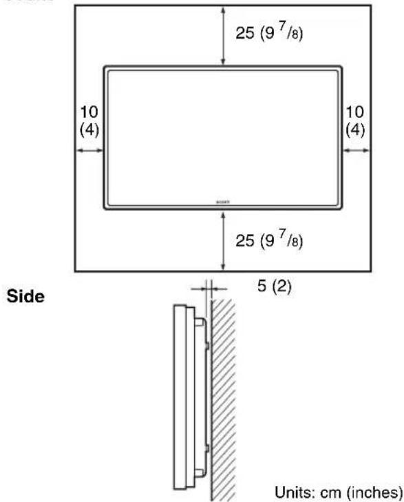
When mounting the display horizontally Front
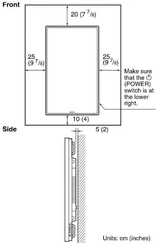
When mounting the display vertically
Avoid high temperatures and high humidity
If this unit might be exposed to high temperatures or high humidity when in use, or where the temperature can change rapidly because of air conditioning or the like, condensation may form inside the protective glass of the display monitor.
Location and Function of Parts and Controls
Front
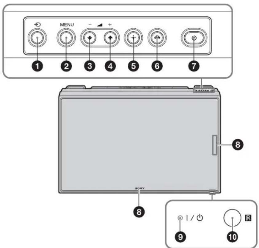
INPUT) button
Press to select a signal to be input from the INPUT or OPTION connector.
The signal to be input switches as follows each time you press the INPUT button.
When an optional adaptor supporting the video signal is not installed in the OPTION slot, OPTION will be skipped.
2 MENU button (page 20)
34 - / + / 口 /口 (volume/cursor) button
Press to control speaker volume. When the menu is displayed, press to move the cursor or set a value.
ENTER) button
Press to set your choice.
RETURN) button
This returns to the preceding menu screen.
(POWER) switch
Switches the display on or off (standby).
3 Sony logo
The Sony logo lights up.
You can switch the logo that lights on the menu according to the direction of setup. See "Logo" on page 31.
9 | (Power/Stand by) indicator
- Lights up in green when the display is switched on.
- Lights up in red when the display is in standby mode. Lights up in orange when the display enters the power saving mode while a signal is input from a PC.
When the indicator blinks in red, see page 38.
Note
When the "LED" option in the "Multi Display" settings is set to "Off" and the "Position" option is not set to the right-bottom, the indicator does not light up in green even when the display is turned on, except for the case of no signal or an unsupported signal.
Remote control sensor
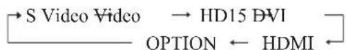
Side
| Connector Description | |
| 1 AC IN socket | Connect the supplied AC power cord to this socket and to a wall outlet. Once you connect the AC power cord, the indicator lights up in red and the display goes into the standby mode. See page 18. |
| 2 SPEAKER socket | Connect the speakers SS-SPG02 (not supplied) to this socket. For more details on connecting the speakers, see the operating manual that came with the speakers. For details on how to route the speaker cords, see page 19. |
| 3 REMOTE (10BASE-T/100BASE-TX) | Serves to connect the display to a network, using a 10BASE-T/100BASE-TX LAN cable. You can assign various settings and control the display via the network from a PC. Caution · When you connect the LAN cable of the unit to peripheral device, use the supplied cable to prevent malfunction due to radiation noise. · For safety, do not connect the connector for peripheral device wiring that might have excessive voltage to this port. Follow the instructions for this port. Note When using this connector, select “Display” in “Network Port”. (page 31) |
| 4 AUDIO (Stereo mini jack) | Outputs an audio of the signal currently indicated on the screen. Outputs an audio signal corresponding to the active* picture while in the “P&P” or “PinP” mode. Note Settings assigned in “Sound Mode” will not be reflected. |
| 5VIDEO | S VIDEO IN (Mini DIN 4-pin): Connects to the S Video output of a piece of video equipment. VIDEO IN (BNC): Connects to the video output of a piece of video equipment. VIDEO OUT (BNC): Connects to the video input of a piece of video equipment. Pictures input from VIDEO IN will be output. AUDIO IN (Stereo mini jack): Connects to the audio output of a piece of video equipment. |
| 6 HD15 (RGB/COMPONENT) (D-sub 15-pin) | HD15 (RGB/COMPONENT) IN: Connects to the analog RGB signal or component signal output of a piece of video equipment or PC. See page 43. AUDIO IN: Inputs an audio signal. Connects to the audio signal output of a piece of video equipment or PC. HD15 (RGB/COMPONENT) OUT: Connects to the analog RGB signal or component signal input of a piece of video equipment or PC. See page 43. Signals input from the HD15 (RGB/COMPONENT) IN connector above will be output. Notes · When inputting a component signal, be sure not to input sync signals to pins 13 and 14. If you do so, the picture may not be displayed properly. · When the display is not connected to an AC power or is in the standby mode, no signal is output from the HD15 (RGB/COMPONENT) OUT. |
| 7 DVI (DVI-D 24-pin) | DVI IN: Connects to the digital signal output terminal of the video equipment or PC. Supports HDCP copy protection. AUDIO IN: Inputs an audio signal. Connects to the audio signal output of a piece of video equipment, etc. |
| 8 HDMI IN | HDMI (High-Definition Multimedia Interface) provides an interface between the display and any HDMI-equipped audio/video equipment, as well as PC. You can enjoy enhanced or high-definition video, and two-channel digital audio. The appropriate mode for a piece of audio/video equipment or PC is automatically selected in accordance with the connected equipment. Note Be sure to use only an HDMI cable (not supplied) that bears the HDMI logo. We recommend that you use a Sony HDMI cable (high speed type). |
Connector Description
OPTION slot
(VIDEO/COM port)
This slot supports video signals and communication functions. Attach an optional adaptor
(the BKM-FW series) in this slot to extend monitor functions. See page 17.
- The status when the sound is output and the input signal can be switched.
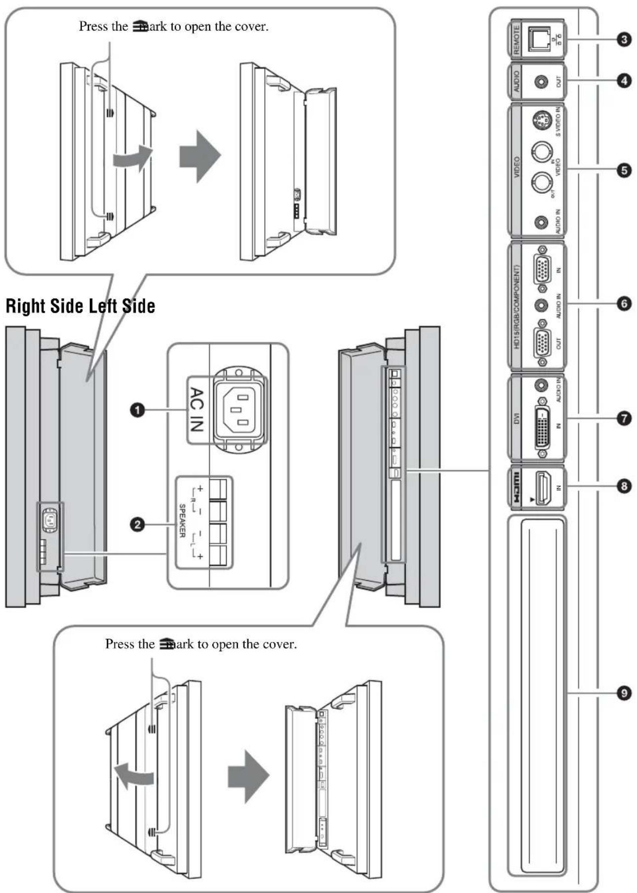
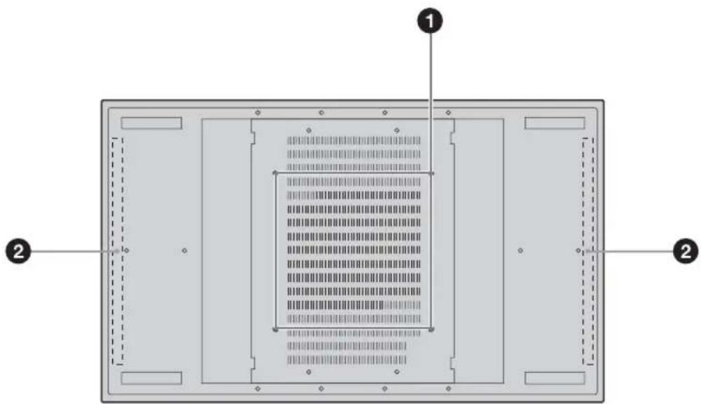
Rear
GB
Parts Description
Stand installation holes Screw holes conforming to VESA standard. (Pitch: 400mm× 400mm ,Screw:M6)
Speaker installation Attach the dedicated speakers SS-SPG02. positions
Remote Control
Button Description
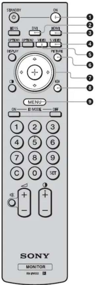
POWER ON switch
Press to turn the display on.
DVI button
Press to select the signal input to the DVI port.
HDMI button
Press to select the signal input to the HDMI port.
SVIDEO button
Press to select the signal input to the SVIDEO IN connector from a piece of video equipment.
⑤VIDEO button
Press to select the signal input to the VIDEO IN connector from a piece of video equipment.
PICTURE button
Selects "Picture Mode". Each press toggles between "Vivid", "Standard", "Custom", "Conference", and "TC Control".
7 念 / 念 /念 /念 /念 buttons
The 12 / 12 / 12 buttons move the menu cursor and set values, etc. Pressing sets the selected menu or setting items.
In the "PAP" mode, you can switch the Picture and Picture setting. See page 15.
按钮
Press to change the aspect ratio. See page 14.
9 MENU button
Press to show menus. Press again to hide them. See page 20.
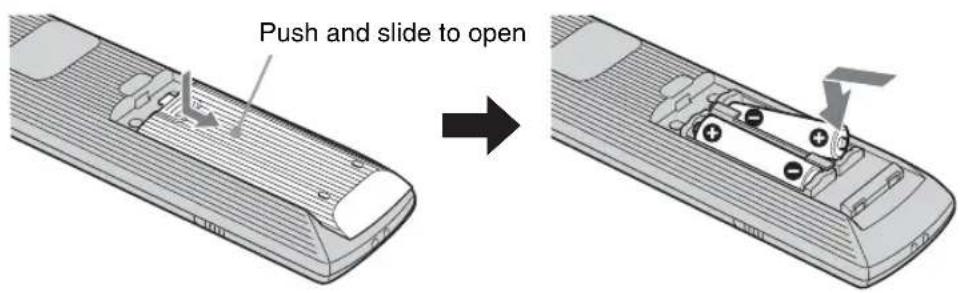
Notes
The 5 button and button have a tactile dot. Use the tactile dot as a reference when operating the display.
- Insert two size AA (R6) batteries (supplied) by matching the and on the batteries to the diagram inside the remote control's battery compartment.
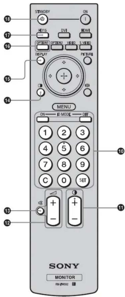
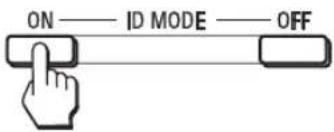
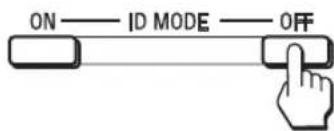
ID MODE (ON/0-9/SET/C/OFF) buttons
You can operate a specific display without affecting other displays installed at the same time.
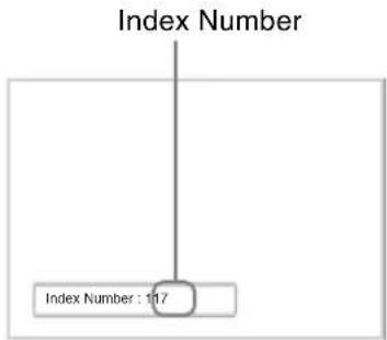
- ON button: Press to show the "Index Number" on the screen.
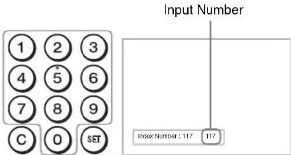
- 0-9 button: Press to enter the "Index Number" of the display you want to operate.
- SET button: Press to set the input "Index Number".
- C button: Press to clear the input "Index Number".
- OFF button: Press to return to the normal mode. See page 16.
1 button
Adjusts the picture (contrast) level.
12 button
Press to adjust the volume.
13 button
Press to mute the sound. Press again to restore sound.
14 button
Selects the "PAP" (Picture And Picture) mode. Each press toggles between "P&P", "PinP" and the single-screen picture. See page 15.
15 DISPLAY button
Press to display the currently selected input, the type of the input signal and the "Aspect" setting on the screen. Press again to hide them. If this displayed information is left undisturbed for a short time, it will disappear automatically.
16 OPTION 1 button
When an optional adaptor is installed, selects an input signal from the equipment connected to the optional adaptor.
If the installed optional adaptor has multiple input connectors, each press of the button toggles between the input signals.
HD15 button
Press to select the input signal of the HD15 (RGB/COMPONENT) connector. The RGB signal or component signal is selected automatically or manually in accordance with the menu settings.
13 STANDBY button
Press to change the display to the standby mode.
Notes
You cannot use the OPTION 2 button on this display.
Special Buttons on the Remote Control
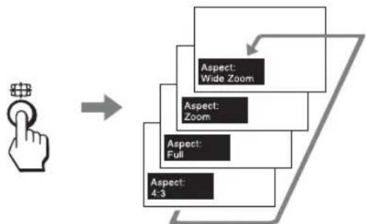
Using the Wide Mode
You can change the aspect ratio of the screen.
Tip
You can also access the "Aspect" settings in the "Screen" settings. See page 27, 28.
For input from video equipment such as Video, DVD, etc. (other than PC input)
4:3 Original Source

Wide Zoom
Zoom

Full
4:3
16:9 Original source
Wide Zoom
Zoom

Full
4:3
For PC Input
Illustrations below indicate the input resolution of 800× 600
Real
Full 1
Full 2
Note
If the input resolution is higher than the panel resolution (1,920× 1,080) , the display of Real is the same as Full 1.
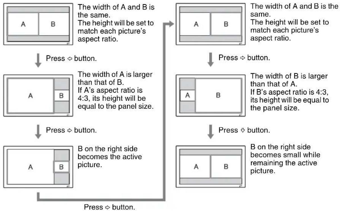
Using the PAP Setting
You can show two pictures from different signal sources, such as a PC and a video, side by side. You can also swap the active pictures, or change the balance of picture sizes. You can also access the "PAP Setting" in the "Screen" settings. See page 25.


Cursor showing active picture
For P&P
For PinP
Tips
- The cursor indicating the active picture will disappear after 5 seconds.
The picture can be adjusted to 15 sizes. (For P&P)
Using the ID MODE button
You can operate a specific display without affecting other displays installed at the same time.
1 Press ON button.
Display's "Index Number" appears in black characters on the lower left menu on the screen. (Every display is allocated an individual preset "Index Number" from 1 to 255.)
2 Input the "Index Number" of the display you want to operate using the 0 - 9 buttons on the remote control.
The input number appears right next to the "Index Number" of each display.
3 Press SET button.
The characters on the selected display change to green while the others change to red.

You can operate the specified display indicated with green characters only. Only the operation of POWER ON switch and STANDBY/ID MODE-OFF button is effective t other displays, as well.
4 When all of the setting changes have been completed, press OFF button.
The display returns to the normal screen.
To correct the Index Number
Press the C button to clear the current input "Index Number". Return to Step 2, and input a new "Index Number".

Tip
To change the "Index Number" of the display, see "Index Number" in "Control Setting" on page 29.
Optional Adaptors
The terminal of the OPTION slot (page 10) on the side of the equipment is a slot-in type. It can be switched to the following optional adapter (not supplied).
For details on installation, consult your Sony dealers. For details on the optional adaptors for system expansion, BKM-FW series, see each instruction manual.
COMPONENT/RGB INPUT Adaptor BKMFW11
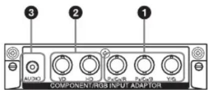
Y/G, R / C_B / B PR / CR / R IN (BNC): Connects to the analog RGB signal or component signal output of a piece of video equipment or PC.
HD, VD IN (BNC): Connects to the synchronization signal output of a PC.
Note
When inputting a component signal, be sure not to input sync signals to the HD and VD connectors. If you do so, the picture may not be displayed properly.
3 AUDIO (Stereo mini jack): Inputs an audio signal. Connects to the audio output of a piece of video equipment or PC.
HDMI INPUT Adaptor BKM-FW15
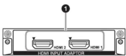
HDMI 1/HDMI 2 IN: HDMI (High-Definition Multimedia Interface) provides an interface between the display and any HDMI-equipped audio/video equipment, as well as PC. You can enjoy enhanced or high-definition video, and two-channel digital audio. You can also connect a piece of DVI-equipped equipment to your display by using an HDMI-to-DVI cable (not supplied). The appropriate mode for a piece of audio/video equipment or PC is automatically selected in accordance with the connected equipment.
Note
Be sure to use only an HDMI cable (not supplied) that bears the HDMI logo. We recommend that you use a Sony HDMI cable (high speed type).
HD-SDI/SDI INPUT Adaptor BKM-FW16
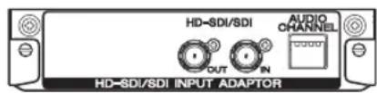
Connects to the HD-SDI signal output of a piece of video equipment.
For details, see the instruction manual of the BKMFW16.
MONITOR CONTROL Adaptor BKM-FW21
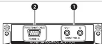
1 CONTROL S IN/OUT (Mini jack): You can control pieces of multiple equipment with a single remote control when the display is connected to the CONTROL S connector of the video equipment or another display. Connect the CONTROL S OUT connector on this adaptor to the CONTROL S IN connector of the other equipment, and connect the CONTROL S IN connector on this adaptor to the CONTROL S OUT connector of the other equipment.
2 REMOTE (D-sub 9-pin): This connector allows remote control of the display using the RS-232C protocol. For details, contact your authorized Sony dealers.
Notes
- The REMOTE connector and the REMOTE (LAN) connector ③ (page 9) on the side of the equipment cannot be used at the same time.
- When using the REMOTE connector, select "Option" in "Network Port". (page 31)
STREAMING RECEIVER Adaptor BKM-FW50
For details, see the instruction manual of the BKM-FW50.
Note
You cannot use the REMOTE connector of this display if the adaptor is connected to this display.
Connections
Before you start
- First make sure that the power of each piece of equipment is turned off.
- Use cables suitable for the equipment to be connected.
- Connect the cables, fully inserting them into the connectors or jacks. A loose connection may cause hum and other noise.
- To disconnect the cable, pull it out by grasping the plug. Never pull the cable itself.
See the instruction manual of the equipment to be connected, too. - Insert the plug securely into the AC IN socket.
- Use one of the two AC plug holders (supplied) to securely hold the AC plug.
Connecting the Speakers
Connect the speakers SS-SPG02 (not supplied). Please be sure to connect the speakers correctly. For more details on connecting the speakers, see the operating manual of the speakers. For details on how to route the speaker cords, see page 19.
Connecting the AC Power Cord
1 Plug the AC power cord into the AC IN socket. Then, attach the AC plug holder (supplied) to the AC power cord.
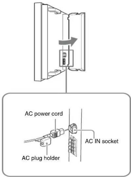
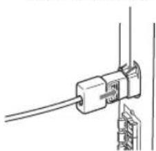
2 Slide the AC plug holder over the cord until it connects to the AC IN socket cover.
AC IN socket cove
To remove the AC power cord
After squeezing the AC plug holder and freeing it, grasp the plug and pull out the AC power cord.
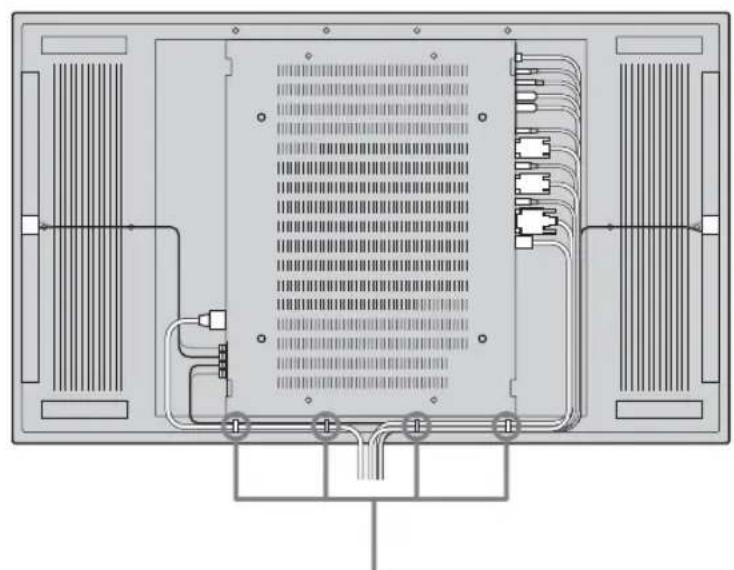
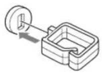
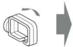
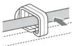
Cable Management
Using the cable holders
You can neatly bundle the cables with the cable holders (× 4) provided. Attach the cable holders as shown in the illustrations below.
Rear
(1)

②
(3)
Using the Settings
Overview of the Menus
The settings provide you access to the following features:
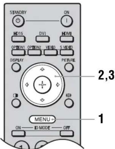
1 Press MENU button.
2 Press to highlight the desired menu icon.
3 Press or
To exit the menu, press MENU button.
To change the on-screen language
Select the desired language for on-screen settings and messages from "English", "Français", "Deutsch", "Espanol", "Italiano" or "日本語" "English" (English) is set for the default setting. See page 29.
Settings Allows you to set/change
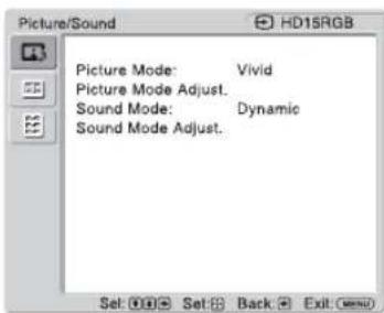
Picture/Sound
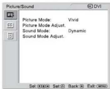
Picture Mode: (page 21, 23)
Picture Mode Adjust. (page 21, 23)
Sound Mode: (page 22, 24)
Sound Mode Adjust. (page 22, 24)
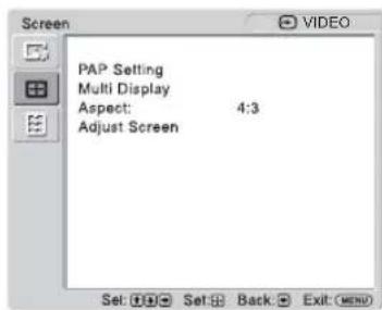
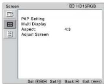
Screen
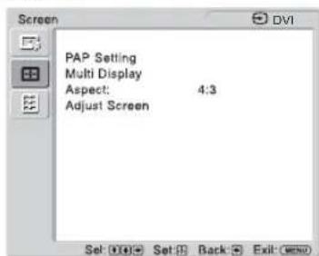
PAP Setting (page 25, 28)
Multi Display (page 26, 28)
Aspect: (page 27, 28)
Adjust Screen (page 27, 28)
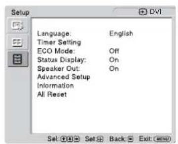
Setup
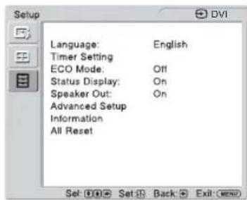
Language: (page 29)
Timer Setting (page 29)
ECO Mode: (page 29)
Status Display: (page 29)
Speaker Out: (page 29)
Advanced Setup (page 29)
Information (page 32)
All Reset (page 32)

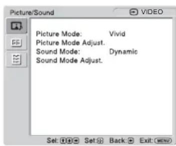
Picture/Sound Settings
For Video Input
To highlight an option and to change settings, press 念 /念/念/念
Press ① confirm the selection.
The "Picture/Sound" settings include the following options:
Picture Mode
"Vivid": Select for enhanced picture contrast and sharpness.
"Standard": Select for standard picture settings.
"Custom": Allows you to store preferred settings.
"Conference": Adjusts the picture quality for video conferencing under fluorescent lights.
"TC Control": The setting is common with "Vivid". In addition, you can use the "True Color Control" function (after-mentioned).
Tip
To change from one "Picture Mode" option to another, you can also use PICTURE on the remote control instead.
Note
"Conference" may not be effective depending on the environment or the video conference system under use. In this case, adjust the picture quality, switch to other settings of "Picture Mode", etc.
Picture Mode Adjust.
"Backlight": Adjusts to brighten or darken the screen.
"Contrast": Adjusts picture contrast.
"Brightness": Adjusts to brighten or darken the picture.
"Chroma": Adjusts to increase or decrease color intensity.
"Phase": Adjusts the color tones of the picture.
"Sharpness": Adjusts to sharpen or soften the picture.
"Noise Reduction": Select to reduce the noise level of connected equipment. Select from "Off", "Low", "Mid", "High" to set the noise level.
"CineMotion": Select "Auto" to optimize the screen display automatically detecting film content. Moving picture will appear clearer and more natural looking. Select "Off" to disable the detection.
Note
"CineMotion" may not be correctly processed depending on the input signal pattern.
"Dynamic Picture": Select "On" to enhance contrast by making white brighter and black darker.
"Gamma Correct": Balances the light and dark portions of pictures. Select from "High", "Mid", "Low", "DICOM GSDF Sim." to make settings.
Notes
- You cannot set "Gamma Correct" when "Picture Mode" is set to "Conference".
- "DICOM GSDF Sim." can only be set when there is a DVI or HDMI input. Gamma setting is simulated by the Grayscale Standard Display Function (GSDF) of the Digital Imaging and Communications in Medicine (DICOM) standards. However, this setting is for reference only and cannot be used for medical diagnosis.
"Color Temp.":White tone can be adjusted to suit your preference. The factory default settings are adjusted to color temperature.
"Cool": Select to give the white colors a blue tint.
"Neutral": Select to give the white colors a neutral tint.
"Warm": Select to give the white colors a red tint.
"Custom": Enables a broader range of white tone to be set than above.
Tip
Restores the default settings by selecting "Reset" on the tone adjusting screen.
"Brightness Boost": Emphasizes the brightness of the image.
Notes
- You can only set "Brightness Boost" when "Picture Mode" is set to "Vivid".
- When "Brightness Boost" is set to "On", you cannot adjust the "Backlight", "Contrast", "Brightness" or "Color Temp." settings.
- When "Brightness Boost" is set to "On", "Backlight" is set to "Max" and "ECO Mode" is switched "Off", the brightness is at its maximum.
"True Color Control": You can adjust the details of hue and saturation for each of 4 colors: red, green, yellow, blue, and you can highlight specific colors in the image. Select the color which you want to adjust, and you can check and see which part of current image will be adjusted. Then you can adjust it using the matrix dialog.
Notes
- This option can be adjusted when "Picture Mode" is set to "TC Control".
- In "PAP" mode, you cannot select this option. Even if you select this option in the single-picture screen, the setting of this option may not be applied in the "PAP" mode
"Reset": Resets all settings of "Picture Mode Adjust." to default settings.
Notes
- "Phase" is not available when the input is Video or S Video and the color system of video signal is not NTSC.
- "Dynamic Picture" is not available when "Picture Mode" is set to "Conference" or "TC Control."
- You can make settings and adjustments for each "Picture Mode" but "Backlight," "Noise Reduction" and "CineMotion" settings are common for all "Picture Mode."
- "Dynamic Picture" and "CineMotion" do not function in PAP mode.
Sound Mode
You can adjust the sound output from the speakers SS-SPG02 (not supplied) with various "Sound Mode" settings.
"Dynamic": Select to enhance treble and bass.
"Standard": Flat setting.
"Custom": Allows you to store preferred settings.
Sound Mode Adjust.
"Treble": Adjusts to increase or decrease higher-pitched sounds.
"Bass": Adjusts to increase or decrease lower-pitched sounds.
"Balance": Adjusts to emphasize left or right speaker balance.
"Surround": Select the surround mode according to the type of picture.
"Off": No surround output.
"Hall": When desiring to give the stereo sound of movies or music programs a greater sense of presence.
"Simul.": When desiring to give ordinary monaural programs or news telecasts an enhanced sense of presence using simulated stereo sound.
"Reset": Resets all settings of "Sound Mode Adjust." to default settings.
Tips
- You can alter the "Picture Mode Adjust." settings ("Contrast", "Brightness", "Chroma", etc.) for each "Picture Mode".
- You can adjust the "Sound Mode Adjust." settings ("Treble" and "Bass") when the "Sound Mode" is set to "Custom".
Note
In the "PAP" mode, only "Picture/Sound" settings for the active picture can be adjusted.
For PC Input
When input is switched to a PC input source, the "Picture/Sound" settings specific to PC input are applied.
The "Picture/Sound" settings for a PC include the following options:
Picture Mode
"Vivid": Select for enhanced picture contrast and sharpness.
"Standard": Select for standard picture settings.
"Custom": Allows you to store preferred settings.
"Conference": Adjusts the picture quality for video conferencing under fluorescent lights.
"TC Control": The setting is common with "Vivid". In addition, you can use the "True Color Control" function (after-mentioned).
Tip
To change from one "Picture Mode" option to another, you can also use PICTURE on the remote control instead.
Note
"Conference" may not be effective depending on the environment or the video conference system under use. In this case, adjust the picture quality, switch to other settings of "Picture Mode", etc.
Picture Mode Adjust.
"Backlight": Adjusts to brighten or darken the screen.
"Contrast": Adjusts picture contrast.
"Brightness": Adjusts to brighten or darken the picture.
"Gamma Correct": Balances the light and dark portions of pictures. Select from "High", "Mid", "Low", "DICOM GSDF Sim." to make settings.
Notes
- You cannot set "Gamma Correct" when "Picture Mode" is set to "Conference".
- "DICOM GSDF Sim." can only be set when there is a DVI or HDMI input. Gamma setting is simulated by the Grayscale Standard Display Function (GSDF) of the Digital Imaging and Communications in Medicine (DICOM) standards. However, this setting is for reference only and cannot be used for medical diagnosis.
"Color Temp": White tone can be adjusted to suit your preference. The factory default settings are adjusted to color temperature.
"Cool": Select to give the white colors a blue tint.
"Neutral": Select to give the white colors a neutral tint.
"Warm": Select to give the white colors a red tint.
"Custom": Enables a broader range of white tone to be set than above.
Tip
Restores the default settings by selecting "Reset" on the tone adjusting screen.
"Brightness Boost": Emphasizes the brightness of the image.
Notes
- You can only set "Brightness Boost" when "Picture Mode" is set to "Vivid".
- When "Brightness Boost" is set to "On", you cannot adjust the "Backlight", "Contrast", "Brightness" or "Color Temp." settings.
- When "Brightness Boost" is set to "On", "Backlight" is set to "Max" and "ECO Mode" is switched "Off", the brightness is at its maximum.
"True Color Control": You can adjust the details of hue and saturation for each of 4 colors: red, green, yellow, blue, and you can highlight specific colors in the image. Select the color which you want to adjust, and you can check and see which part of current image will be adjusted. Then you can adjust it using the matrix dialog.
| Notes ·This option can be adjusted when “Picture Mode” is set to “TC Control”. ·In “PAP” mode, you cannot select this option. Even if you select this option in the single-picture screen, the setting of this option may not be applied in the “PAP” mode “Reset”: Resets all settings of “Picture Mode Adjust.” to default settings. Note You can make settings and adjustments for each “Picture Mode” but “Backlight” is common for all “Picture Mode.” | |
| Sound Mode | You can adjust the sound output from the speakers SS-SPG02 (not supplied) with various “Sound Mode” settings. “Dynamic”: Select to enhance treble and bass. “Standard”: Flat setting. “Custom”: Allows you to store preferred settings. |
| Sound Mode Adjust. | “Treble”: Adjusts to increase or decrease higher-pitched sounds. “Bass”: Adjusts to increase or decrease lower-pitched sounds. “Balance”: Adjusts to emphasize left or right speaker balance. “Surround”: Select the surround mode according to the type of picture. “Off”: No surround output. “Hall”: When desiring to give the stereo sound of movies or music programs a greater sense of presence. “Simul”: When desiring to give ordinary monaural programs or news telecasts an enhanced sense of presence using simulated stereo sound. “Reset”: Resets all settings of “Sound Mode Adjust.” to default settings. |
Tips
- You can alter the "Picture Mode Adjust." settings ("Contrast", "Brightness", "Chroma", etc.) for each "Picture Mode".
- You can adjust the "Sound Mode Adjust." settings ("Treble" and "Bass") when the "Sound Mode" is set to "Custom".
Notes
Chroma", Phase", Sharpness", Noise Reduction", CineMotion", and Dynamic Picture" are not available for PC input.
- In the "PAP" mode, only "Picture/Sound" settings for the active picture can be adjusted.
Screen Settings
For Video Input
To highlight an option and to change settings, press 念 /念/念/念
Press to confirm the selection.
The "Screen" settings include the following options:
PAP Setting
Allows you to show two pictures from different signal sources, such as a PC and a video, side by side.
"PAP"
"Off": Disables "PAP" function.
"P&P": Shows two pictures side by side at the same time.
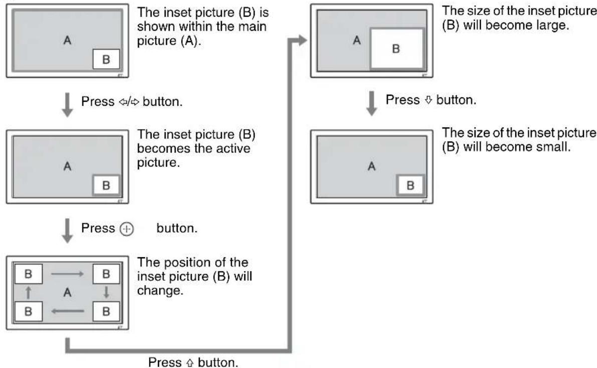
"PinP": Displays two pictures as the inset picture within the main picture.
For P&P
"Active Picture": Selects the screen to operate.
"Left": You can activate the left picture to operate it.
"Right": You can activate the right picture to operate it.
"Swap": Swaps the two pictures side by side.
"Picture Size": Adjusts the balance between two pictures side by side. Adjust the balance by pressing or button, and then press button to set the adjustment. (page 15)
For PinP
"Active Picture": Selects the screen to operate.
"Main": You can activate the main picture to operate it.
"Sub": You can activate the inset picture to operate it.
"Swap": Swaps the main and the inset pictures.
"Picture Size": Adjusts the size of the inset picture. Select from "Large" or "Small".
"Picture Position": Adjusts the position of the inset picture with 12 / 12 / 12 / 12 , then press .
Notes
- In "PAP" mode, "Picture Mode" and "Sound Mode" are reflected in the main picture settings.
- You cannot change the aspect ratio in the "PAP" mode. The picture is displayed in the last aspect ratio used prior to selecting "PAP" mode.
Available combination of two pictures
1) Supported when "Display" is set to "YUV" or when "Option" is set to "RGB" in "RGB/YUV".
2) Supported when "Display" is set to "RGB" or when "Option" is set to "YUV" in "RGB/YUV".
Tip
Output from BKM-FW50 is considered as RGB output shown in the table in the "PAP" mode.
Multi Display
Allows you to make settings for connecting multiple displays to form a video wall.
"Multi Display"
"Off": Uses a single screen.
2 × 2" / "3 × 3" / "4 × 4" : Sets to connect multiple displays such as 2, 3 or 4 displays both vertically and horizontally.
1 × 2 1 × 3 1 × 4 : Sets to connect multiple displays such as 2, 3 or 4 displays horizontally.
12 × 1 " 13 × 1 " 14 × 1 ": Sets to connect multiple displays such as 2, 3 or 4 displays vertically.
"Position": Select the position of each display in the arrangement of the video wall with 12 / 12 / 12 . Press to set the position.
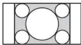
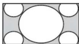
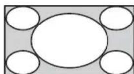
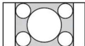
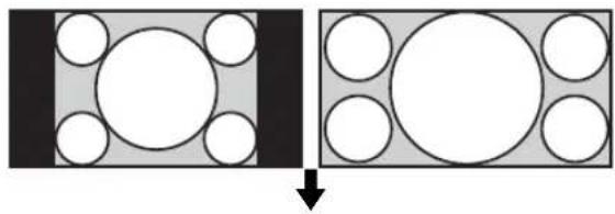
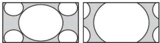
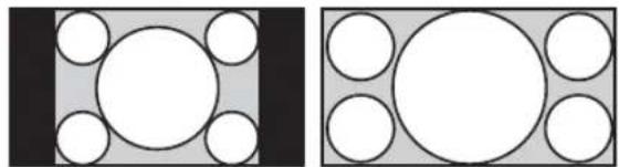
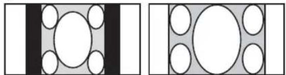
"Output Format": Selection of two picture output formats will be available as shown in the figures. By simply selecting either format, suitable picture output will be available without manually adjusting the horizontal and vertical shift. Select either "Tiles" or "Window".
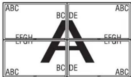
"Tiles"
To show full signal on each display.
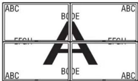
"Window"
To show one large picture with multi display naturally. Part of the signal will go behind the bezel area.
"LED": "On" makes the / 山 indicator on the front panel (page 7) to be continually turned on, and "Off" makes the indicator on the front panel to be continually turned off.
Notes
- "Multi Display" can display an enlarged picture keeping the current "Aspect" setting as much as possible for video input, and can display an enlarged picture of which "Aspect" is set to "Full 2" for PC input.
- You can set the "Multi Display" only when the "PAP" function is disabled.
- When "Position" is set to the right-bottom, the indicator lights up even if "LED" is set to "Off". The indicator also lights up even when the display is off (standby), errors are detected, or the display is in sleep mode including the case of no signal or unsupported signal.
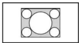
Aspect
"Wide Zoom": Select to enlarge to fill screen with minimum distortion.
"Zoom": Select to enlarge the original picture without distorting the aspect ratio. See page 14.
"Full": Select to enlarge the original picture horizontally to fill the screen when the original source is 4:3 (Standard definition source). When the original source is 16:9 (High definition source), select this mode to display 16:9 picture in original size.
"4:3": Select to display all the pictures in original size to 4:3 aspect ratio..
Tips
- To change from one "Aspect" option to another, you can also use on the remote control.
- Select "Zoom" to display movies and other DVD content with black bands, using the entire viewable area of the screen.
Notes
- You cannot change the aspect ratio in the "PAP" mode. The picture is displayed in the last aspect ratio used prior to selecting "PAP" mode.
- You cannot set the "Aspect" while using the "Multi Display" function.
Adjust Screen
"H Size": Allows you to adjust the size of the picture horizontally. Press and press 和 choose a correction.
"H Shift": Allows you to move the position of the picture left and right in the window. Press and press to choose a correction.
"V Size": Allows you to adjust the size of the picture vertically. Press 口 and press to choose a correction.
"V Shift": Allows you to move the position of the picture up and down in the window. Press / and press to choose a correction.
"Reset": Resets all settings of "Adjust Screen" to default settings.
Notes
- "Adjust Screen" is not available while using the "PAP" function.
- If there is no signal currently being input, none of the "Screen" settings options, except for "PAP Setting" and "Multi Display" can be selected.
For PC Input
When input is switched to PC input source, the "Screen" settings specific for PC input are applied. The "Screen" settings for a PC include the following options:
PAP Setting
See "PAP Setting" for video input (page 25).
Multi Display
See "Multi Display" for video input (page 26).
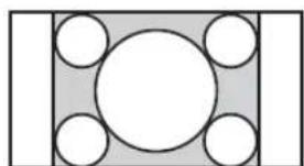
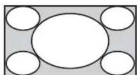
Aspect
"Full 1": Select to enlarge the picture to fill the display area in the vertical direction, keeping its original horizontal-to-vertical aspect ratio. A black frame will appear on the surrounding of the picture.
"Full 2": Select to enlarge the picture to fill the display area.
"Real": Select to display the picture in its original number of dots.
Notes
- You cannot change the aspect ratio in the "PAP" mode. The picture is displayed in the last aspect ratio used prior to selecting "PAP" mode.
- You cannot set the "Aspect" while using the "Multi Display" function.
- If the input resolution is higher than the panel resolution (1,920 × 1,080) , the display of "Real" is the same as "Full 1".
Adjust Screen
"Auto Adjustment": Select "OK" to automatically adjust the display position and phase of the picture when the display receives an input signal from the connected PC. Note that "Auto Adjustment" may not work well with certain input signals. In such cases, manually adjust the options below.
"Phase": Select to adjust the phase when the screen flickers.
"Pitch": Select to adjust the pitch when the picture has unwanted vertical stripes.
Notes
- "Auto Adjustment," "Phase," "Pitch" are not available when digital signal such as DVI or HDMI is input.
- When performing "Auto Adjustment", display an image that is bright all over. If you do not, the position of the picture may be incorrectly adjusted.
"H Size": Allows you to adjust the size of the picture horizontally. Press / and press 串 choose a correction.
"H Shift": Allows you to move the position of the picture left and right in the window. Press and press to choose a correction.
"V Size": Allows you to adjust the size of the picture vertically. Press / and press to choose a correction.
"V Shift": Allows you to move the position of the picture up and down in the window. Press / and press to choose a correction.
"Reset": Resets all settings of "Adjust Screen" to default settings.
Note
If there is no signal currently being input, none of the "Screen" settings options, except for "PAP Setting" and "Multi Display" can be selected.

Setup Settings
To highlight an option and to change settings, press // //
Press to confirm the selection.
The "Setup" settings include the following options:
| Language | Select to display all on-screen settings in your language of choice: “English”, “François”, “Deutsch”, “Espanol”, “Italiano” or “日本語 |
| Timer Setting | You can adjust time, display the built-in clock, or set the timer to make the display power on/off at a predetermined time. “Clock Set”: Sets the day of the week and the hour of the day. “Date Set”: Sets the date (year, month, date). The day is automatically set. “Time Set”: Sets the time. “Clock Display”: Displays the currently set time on the screen when set to “On,” by pressing the display button on the remote control. “On/Off Timer”: Sets the day of the week and the hour of the day. |
| Note If the built-in clock tends to lose time, the internal battery may be exhausted. Please contact your authorized Sony dealer to have the battery replaced. | |
| ECO Mode | “Off”: Select to view picture without the benefit of power saving. “Low”/“High”: Select to change brightness of the backlight and reduce power consumption. |
| Status Display | "On" makes input signal and "Aspect" information appear on the screen for about 5 seconds when the display is turned on, and the input signal information appear for about 5 seconds when the input signal is switched, while "Off" disables display of status information. Tip You can display the input signal and "Aspect" information by using DISPLAY on the remote control regardless of the "Status Display" setting. |
| Speaker Out | "On": Enables sound to be emitted from the speakers. "Off": Disables sound to be emitted from the speakers. |
| Advanced Setup | "Control Setting": This menu is used for settings of operation of the display and the remote control. "Index Number": You can change the index number of the display if necessary. Select to set the index number of the display with ⋅/ ⋅ and press ⋅ (ENTER) to confirm the setting. Note When you set the "Index Number", use the buttons on the display. The "Index Number" cannot be set with the remote control. "Control Mode" "Display+Remote": You can operate the display with the control buttons on the display and the remote control. "Display Only": Enables the remote control function. You can make settings for the display only using the control buttons on the display. "Remote Only": Enables the controls on the display. You can make settings for the display only using the remote control. |
Note
When this item is operated, the available modes will differ depending on whether you select by the remote control or the display. When setting this item with on the remote control, you can select only "Display+Remote" or "Remote Only". When setting this item with (ENTER) on the display, you can select only "Display+Remote" or "Display Only".
"Auto Screen Adjust"
"On": The settings such as picture size and position are saved for each input signal, and the last settings are automatically applied each time the input signals are switched.
"Off": The "Auto Screen Adjust" is disabled even when input signals are switched and the default settings are applied.
Note
The "Auto Screen Adjust" function only works during RGB input.
"Auto Shut Off":
"On": The display automatically enters the standby mode when a signal is not input to the Video or S Video input connectors for more than about 5 minutes. The display automatically enters the power saving mode when a signal is not input to the DVI, HDMI or HD15 (RGB/Component) input connectors for more than about 30 seconds.
"Off": The display is not turned off automatically even when no signal is input to any connector.
Tips
- While in the standby mode, press the (POWER) switch on the display or the POWER ON switch on the remote control to turn the display on. In the power saving mode, the display is turned on automatically when a signal is input.
- This function is not available when "On-Screen Logo" is set to "On", the screenshot function is activated, or PAP is selected.
"Overscan": Selects whether to display images with overscan or justscan.
"Auto": Switches automatically signal image which are supposed to be DTV to image with overscan.
"On": Displays image with overscan.
"Off": Displays image with justscan.
Note
If "Overscan" is set to "Off," DTV signal image may be displayed like PC signal display. Example: 480P 720× 480 / 60
"Sync Mode": Sets the mode according to the signal input at pin 13 of the HD15 (RGB/COMPONENT) IN connector.
"H/Comp": Select when a horizontal synchronous signal or a composite synchronous signal is input.
"Video": Select when a video signal is input.
Notes
- "Sync Mode" is available only when analog RGB signal is input to HD15 connector.
- Depending on the level of the composite synchronous signal, the image may not be displayed correctly. In this case, change the "Sync Mode" setting.
- There are some inputs for which only synchronizing signals can be selected. In this case, input horizontal/vertical synchronization signals through the pin 13 or 14 of the connectors.
- Sync Mode settings cannot be carried out for the input through the optional adaptors.
- When "Video" is selected in "Sync Mode", you can only set the 575/50i and 480/60i signals.
- When you select the video signal for the synchronous mode setting, you cannot use the PAP function.
“RGB/YUV”
"Display"/"Option": Sets the type of signal for a video device or PC connected to the HD15 (RGB/COMPONENT) terminal of the display or the 5BNC (RGB/COMPONENT) terminal of an optional adaptor.
"Auto": Select to choose either an analog RGB input signal or a component input signal from a connected equipment.
"RGB": Select to choose an analog RGB input signal from a connected equipment.
"YUV": Select to choose a component input signal from a connected equipment.
Note
Select "RGB" to input RGB signals using a composite synchronous signal.
Tip
For the available combination of two pictures, see page 26.
"Color System": Select the color system of video signals from "Auto", "NTSC", "NTSC4.43", "PAL", "PAL-M", "PAL-N" or "PAL60". Select "Auto" to set the color system automatically.
Note
"Color System" is not available for PC input.
"RGB Signal": When a HD15, DVI or HDMI input terminal 1280 × 768/60 or 720 × 480/60 RGB signal is input, this selects whether it works as a video signal or a PC signal.
"Screen Saver": This is a setting to prevent or reduce screen burn or after-image that can occur by long periods of screen display of the same image.
"All White": Displays an all white screen. (Stops automatically after about 30 minutes and the display enters standby mode.)
"Sweep": Scrolls a white bar over the screen.
"Standby": The screenshot operates in standby (page 7) for the time specified in "Timer Setting." (The display is blank during screenshot operation.) When the screenshot ends, normal standby mode is resumed.
"Logo": The Sony logo on the front of the unit lights.
"Position": The logo can be constantly lit at the bottom side of the screen by setting the setup method of the equipment from "Auto," "Landscape," and "Portrait." If "Auto" is selected, Landscape or Portrait will automatically be selected.
"Illumination": Select "Off" to have the logo extinguished. Select "Low" and "High" for the brightness.
"On-Screen Logo"
"On": The model name logo is displayed when the signal is not inputted.
"Off": The model name logo is not displayed when the signal is not inputted.
"Network Port": Sets the network port to operate the display by remote control.
"Off": Select when not using the network port. The power consumption during standby mode can be reduced.
"Option": Allows you to make settings of the display from a PC connected to the REMOTE connector or the LAN connector of the OPTION slot. (page 35)
"Display": Allows you to make settings of the display from a PC connected to the REMOTE (LAN) connector of the display. (page 35)
Tip
When a BKM-FW50 adaptor is inserted in the OPTION slot, "Network Port" is automatically set to "Option".
"IP Address Setup": Sets an IP address to enable communication speed between the REMOTE (LAN) connector of the display or the optional adaptor and the equipment such as a PC connected with the LAN cable.
"Speed Setup": Sets a communication speed between the REMOTE (LAN) connector of the display or the optional adaptor and the equipment such as a PC connected with the LAN cable.
| Tip For details on how to make the settings of “IP Address Setup” and “Speed Setup”, see the section of “Preparations for Using the Network Functions” (page 33). “Power On Delay”: Adjusts the time until power-on. Sets to Off, and 1 to 120 seconds. This suppresses a sudden load fluctuation to the power equipment when multiple units are connected. | |
| Information | Displays the “Date”, “Model Name”, “Serial Number”, “Operation Time”, “Software Version” and “IP Address” of your display. |
| All Reset | Reset all adjustments and settings to factory settings. Note The items included in the “Information” option and the “Index Number” will not be reset. |
Preparations for Using the Network Functions
Precautions
- The software specifications of this display are subject to change for improvements without notice.
- Screens shown by application software may differ slightly from the illustrations shown in this manual.
- For safety, connect the port of this display only to a network where there is no danger of excessive voltage or voltage surges.
- The steps described in this manual are guaranteed only for use under the following environment conditions.
- When using the network functions of the BKM-FW50, see the operating manual of each optional adaptor.
Operating system:
Microsoft Windows XP/Windows Vista
Browser:
Microsoft Internet Explorer 6.0 or later
- To ensure security on the network, setting a username and password is recommended. For information on how to make these settings, see the section "Setup screen" (page 36).
For security settings, refer to your network administrator.
Setting an IP address
The display can be connected to a network with 10BASE-T/100BASE-TX LAN cable.
When connected to a LAN, the IP addresses of the display can be set using one of the following two methods. Consult your network administrator regarding details about IP address selection.
- Assigning a fixed IP address to the display Normally this method should be used. Note that in factory setting, the display is set to obtain an IP address automatically.
- Automatically obtaining an IP address If the network to which the display is connected has a DHCP server, you can have the DHCP server automatically assign an IP address. Note that in this case the IP address may change every time the display in which the display is installed is turned on.
Before setting the IP address, connect the LAN cable to the display to establish the network. After about 30 seconds, turn on the display, and then start making the desired settings.
Assigning a fixed IP address to the display
1 Press MENU to bring up the main menu.
2 Select "Setup" with 和 and press
3 Select "Advanced Setup" with 山 / 山 and press
4 Select "IP Address Setup" with 山 /山 and press
5 Select "Manual" with 豆 /豆 and press
6 Select an desired item to set from "IP Address", "Subnet Mask", "Default Gateway", "Primary DNS", "Secondary DNS" with 口 / 口 and press
7 Set the three digit value (0 to 255) for each of the four box with 1 / 1 on the display or numeric keys on the remote control and press or
8 Set the three digit value (0 to 255) for each of the four boxes and press Repeat the same procedure as step 6 and select the next desired item to set with 喜 /喜 and press
9 After values are set for all the desired items, select "Execute" with 豆 /豆 , then press
Select "Execute" and press An IP address is set manually.
When "Cancel" is selected, the setting will return to the original setting.
Automatically obtaining an IP address
1 Press MENU to bring up the main menu.
2 Select "Setup" with / and press .
3 Select "Advanced Setup" with 山 /山 and press
4 Select "IP Address Setup" with 山 /山 and press
5 Select "DHCP" with 豆 /豆 and press
Select "Execute" and press An IP address is automatically set.
When "Cancel" is selected, the setting will not be executed.
Note
When an IP address is not set properly, the following error codes will be displayed in accordance with the error cause.
Error 1: Communication error
Error 2: The specified IP address is already used for other equipment
Error 3: IP address error
Error 4: Gateway address error
Error 5: Primary DNS address error
Error 6: Secondary DNS address error
Error 7: Subnet mask error
Checking the automatically assigned IP address
1 Press MENU to bring up the main menu.
2 Select "Setup" with 和 / 和 and press
3 Select "Information" with 四 / 四 and press
4 Select "IP Address" with 口 /口 and press
The IP address currently acquired is displayed.
Tip
When an IP address cannot be acquired properly, the previously acquired IP address is shown in "Information" and in "Manual" of "IP Address Setup".
Setting a communication speed
1 Press MENU to bring up the main menu.
2 Select "Setup" with 和 / 和 and press
3 Select "Advanced Setup" with 山 / 山 and press
4 Select "Speed Setup" with 山 /山 and press
5 Select a desired communication speed to set from "Auto", "10Mbps Half", "10Mbps Full", "100Mbps Half", or "100Mbps Full" with 山 /山 and press
When "Auto" is selected, a communication speed appropriate for your network configuration is automatically set.
6 Select "Execute" with 山 /山 and press to reflect the setting.
PC Operation
Controlling the display
You can make various display settings on the screen of the PC.
Make sure that the display, PC, and router or hub are properly connected with the network cable. Then turn on power to the display, the PC, and the router or hub. There are four display screens, divided by function: Information screen, Configure screen, Control screen, and Setup screen.
For details on the functions of buttons, see instructions for each function of the display.
1 Start the browser of the PC (Internet Explorer 6.0 or later).
2 Enter the IP address that was assigned to the display in the previous page as "http://xxx.xxx.xxx.xxx", then press the ENTER key on the keyboard. When a user name and password have been set, the "Network Password" screen appears. Enter the user name and password that were set, and then proceed to the next step.
3 Click the function tab at the top of the screen and select the desired screen.
Setting items on respective screens
When using the LAN function of the display
Information screen
This screen shows the model name, serial number and other display information, as well as the power status and the input signal selection.
The screen is for information only. There are no items that can be set.
Configure screen
Timer
Lets you make settings for the timer function. Click "Apply" when done.
Screen Saver
Lets you make settings for the screenshot function. Click "Apply" when done.
Picture and Picture
Lets you make settings for the Picture and Picture function.
Click "Apply" when done.
Note
Before setting the "Timer" function, make sure to configure the time setting on the Setup screen (page 36).
Control screen
POWER
Switches the display on or off.
INPUT
Lets you select the input signal.
PICTURE MODE
Lets you select the picture mode.
ASPECT
Lets you switch the aspect ratio of the image.
Contrast + / - buttons
Adjust the screen contrast.
Brightness +/- buttons
Adjust the picture brightness.
Chroma +/- buttons
Adjust the color intensity.
Phase +/- buttons
Adjust the color balance.
Reset button
Reset the settings from "Contrast" to "Phase" to their factory default values.
Notes
- If the input signal is Video or S Video and the color system of the video signal is not NTSC, "Phase" is not available.
- "Chroma" and "Phase" are not available for PC input.
- "Normal" at the ASPECT setting corresponds to "4:3" for video input or "Real" for PC input.
Setup screen
This screen lets you set up the Network Password. The factory default settings are as follows:
Name: root
Password: pudadm
After you have made any changes or entered information, click "Apply" at the bottom of each screen to enable the settings.
Special characters cannot be used in the text fields.
Owner Information
Owner
Enter owner information here.
Display Location
Enter information about the display installation location here.
Note
Do not use spaces when entering the information. Doing so may cause the file name to display incorrectly.
Memo
You can enter auxiliary information here.
Time
Time
Enter the time, year, month, and day.
Network
Internet Protocol (TCP/IP)
Select "Specify an IP address" to enter each value in the IP address's numeric string.
Select "Obtain an IP address (DHCP)" to acquire an IP address automatically from the DHCP server. Note that in this case the IP address may change every time the display in which the display is installed is turned on.
Note
The IP address can be set from the menu of the display. For details, see "IP Address Setup" (page 31).
Password
The administrator and user name and password information can be entered here. The administrator name is fixed to "root".
Each can be a maximum of 8 characters long.
Once a user name and password are set, the "Network Password" screen appears whenever the display
control screen of the display is called up. To ensure security on the network, setting a user name and password is recommended.
Mail Report
Error Report
When a display function error has occurred, an error report is immediately sent by e-mail (error notification).
Status Report
The status of the display can be reported via email according to the selected time interval.
Address
Enter the target e-mail address here. Up to four addresses can be specified, for simultaneous sending of an error report. The maximum length for each address is 64 characters.
Mail Account
Mail Address:
Enter the allocated mail address here.
The maximum length for the address is 64 characters.
Outgoing Mail Server (SMTP):
Enter the mail server address here.
The maximum length for the address is 64 characters.
Requires the use of POP Authentication before Send e-mail (POP before SMTP):
If POP authentication is required when connecting to the SMTP server, select this check box.
Incoming Mail Server (POP3):
When POP authentication is used for the "POP before SMTP" setting, enter the POP3 server address here.
Account Name:
Enter the mail account name here.
Password:
Enter the mail password here.
Send Test Mail:
To test whether mail can be sent successfully to the specified address(es), select this check box and click "Apply". A test mail will be sent.
Note
If any of the following items is not set or not set correctly, an error message appears, and test mail cannot be sent:
- Target address
- Mail account address and mail server address (SMTP)
Advanced
Gives access to advanced settings to enable use of various applications on the network. Make the settings as required by the respective application.
Advertisement
Lets you make settings for the Advertisement and Broadcast functions on the network.
ID Talk
Lets you make settings for the ID Talk function. ID Talk is a protocol that allows network-based control of the display. Controlled items include various settings and adjustments such as color temperature and gamma. For information about supported ID Talk commands, contact your local Sony dealer.
SNMP
The display is a network equipment which supports SNMP (Simple Network Management Protocol). Besides standard MIB-II, Sony Enterprise MIB is also supported. This screen allows making settings for SNMP. For information about supported SNMP commands, contact your local Sony dealer.
Returning to default settings
To reset all settings made on the "Setup" screen to the factory default condition, reset to the default settings by assigning the "All Reset" setting, and then assign the appropriate settings of the network again.
Other Information
Troubleshooting
Check whether the indicator is flashing red.
When it is flashing
The self-diagnosis function is activated.
1 Check how many times the indicator flashes and how long it stops flashing.
For example, the indicator flashes 2 times, stops flashing for 3 seconds, and flashes 2 times.
2 Press (POWER) switch on the display to switch off the power, then disconnect the power cord.
Inform your dealer or Sony service center of how the indicator flashes (the number of flashes and the duration of light out).
When it is not flashing
1 Check the items in the table below.
2 If the problem still persists, have your display serviced by qualified personnel
Problem Possible Remedies
| The power switch and control buttons on the display do not work. | ·Check “Control Setting” (page 29). |
| No video signal is output from the HD15 (RGB/COMPONENT) OUT terminal. | ·There is no HD15 (RGB/COMPONENT) OUT output when this device is in standby status or the AC power supply is switched off. |
| No signal is output from the HD-SDI OUT terminal of the BKM-FW16. | ·There is no HD-SDI OUT output when this device is in standby status or the AC power supply is switched off. |
| No picture. | |
| No picture. | ·Check the connection between the video equipment and the display. ·Check the settings of “RGB/YUV” (page 31). ·Try switching input using the INPUT button of the display, or the remote control (page 7, 12). |
| The display turns off automatically. | ·Check if “Timer Setting” is activated (page 29). ·Check if the “Auto Shut Off” function is set to “On” (page 30). ·Check if the room temperature is above 35°C. |
| Poor picture. | |
| No color/Dark picture/The picture is too bright/Color is not correct/The picture gradually becomes dark/Horizontal noise appears on the picture | ·Press PICTURE to select the desired “Picture Mode” (page 12). ·Adjust the “Picture Mode” options in the “Picture/Sound” settings (page 21, 23). ·Check the condition of the signal cable. ·Check if the room temperature is above 35°C. ·Check the settings in “ECO mode.” (page 29) ·When not connecting a video device, do not connect a video cable or conversion connector to the VIDEO OUT terminal. The white areas of the image will be too bright due to the display signal not being terminated. |
| The whole screen is tinged green or purple. | ·Check whether the “RGB/YUV” settings are incorrect (page 31). |
Problem Possible Remedies
No sound/Noisy sound.
| Picture displayed, no sound. | ·Check the volume control. ·Press the remote control or + so that Muting disappears from the screen (page 13). ·Check “Speaker Out” settings (page 29). |
| Remote control does not operate. | ·Check the polarity of the batteries or replace the batteries. ·Point the remote control at the remote control sensor of the display. ·Keep the remote control sensor area clear from obstacles. ·Check “Control Setting” (page 29). ·Check whether a cable is connected to the CONTROL S IN connector (BKM-FW21 not supplied). The remote control cannot be used while the display is controlled via a CONTROL S connection. ·Fluorescent lamps can interfere with remote control operation; try turning off the fluorescent lamps. |
| Cannot connect to the network. | ·Plug the cable firmly into the REMOTE connector. ·Check the network settings of the PC. ·Reset to the default settings by assigning the “All Reset” setting on the “Setup” setting menu, and then assign the appropriate settings of the network again. ·Check the settings in “Network Port.” (page 31) |
| The display control screen (the Web screen displaying the display's GUI) does not appear. | ·Click the refresh or reload button on your Web browser. ·Make sure the IP address is correct. ·Use Internet Explorer 6.0 or later. ·Clear the browser cache. |
Input Signal Reference Chart
PC signals
| Resolution | horizontal frequency (kHz) | vertical frequency (Hz) | |
| 1 | VGA a)-1 (VGA 350) 31.5 70 | ||
| 2 | 640×480@60 Hz 31.5 60 | ||
| 3 | Mac b) 13" 35.0 67 | ||
| 4 | VGA (VGA TEXT) 31.5 70 | ||
| 5 | 800×600@60 Hz (VESA) STD) | 37.9 | 60 |
| 6 | Mac 16" 49.7 75 | ||
| 7 | 1024×768@60 Hz (VESA STD) | 48.4 | 60 |
| 8 | 1024×768@75 Hz (VESA STD) | 60.0 | 75 |
| 9 | 1024×768@85 Hz (VESA STD) | 68.7 | 85 |
| 10 | 1152×864@75 Hz (VESA STD) | 67.5 75 | |
| 11 | Mac 21" | 68.7 | 75 |
| 12 | 1280×960@60 Hz (VESA STD) | 60.0 60 | |
| 13 | 1280×1024@60 Hz (VESA STD) | 64.0 60 | |
| 14 | 1600×1200@60 Hz (VESA STD)* | 75.0 60 | |
| 15 | 848×480@60 Hz (CVT d) | 29.8 | 60 |
| 16 | 848×480@75 Hz (CVT) | 37.7 75 | |
| 17 | 848×480@85 Hz (CVT) | 43.0 85 | |
| 18 | 1280×720@60 Hz (CVT) | 44.8 60 | |
| 19 | 1280×768@60 Hz (CVT) | 47.8 60 | |
| 20 | 1280×768@75 Hz (CVT) | 60.3 75 | |
| 21 | 1280×960@60 Hz (CVT) | 59.7 60 | |
| 22 | 1360×768@60 Hz (CVT) | 47.7 60 | |
| 23 | 800×600@60 Hz (CVT) | 37.4 60 | |
| 24 | 1024×768@60 Hz (CVT) | 47.8 60 | |
| 25 | 1280×1024@60 Hz (CVT) | 63.7 60 | |
| 26 | 1400×1050@60 Hz (CVT)* | 65.3 60 | |
| 27 | 1600×1200@60 Hz (CVT)* | 74.5 60 | |
| 28 | 1920×1080@60 Hz | 66.6 60 | |
| 29 | 1920×1200@60 Hz | 74.0 60 |
TV/Video signals
a) VGA is a registered trademark of International Business Machines Corporation, U.S.A.
b) Macintosh is a trademark of Apple Inc., registered in the U.S. and other countries.
c) VESA is a registered trademark of the Video Electronics Standards Association.
d) VESA Coordinated Video Timing
Notes
- For HDTV signals, input the tri-level sync signal to the 2nd pin of HD15 (RGB/COMPONENT) IN connector.
- If colors appear too light after input of a DVD signal to the display, adjust "Chroma" in the "Picture/Sound" settings.
- When the phase is readjusted, the resolution will be reduced.
- The signals from the Macintosh computer will not be guaranteed for recognizing the digital RGB input.
- You cannot input the signal indicated with * to DVI IN.
Video signals without color burst signal are not guaranteed.
Actual on-screen display of the input signal and the display's status
| On-screen display | Significance |
| 640 × 480 / 60 (e.g.) The selected input signal is a PC signal. | The selected input signal is a PC signal. |
| 480 / 60I (e.g.) The selected input signal is component video. | The selected input signal is component video. |
| NTSC (e.g.) The selected input signal is video signal. | The selected input signal is video signal. |
| Not Supported Signal | The selected input signal is non-supported signal. |
| No Signal There is no input signal. | input signal. |
| HD15 The selected input is HD15. “RGB/YUV” is set to “Auto”. | The selected input signal is non-supported signal. |
| HD15 RGB The selected input is HD15. “RGB/YUV” is set to “RGB”. | The selected input is HD15. “RGB/YUV” is set to “RGB”. |
| HD15 Component The selected input is HD15. “RGB/YUV” is set to “YUV”. | The selected input is HD15. “RGB/YUV” is set to “YUV”. |
| DVI The selected input signal is DVI. | The selected input is DVI. |
| HDMI The selected input signal is HDMI. | The selected input is HDMI. |
| Video The Composite Video signal is selected. | Video signal is selected. |
| S Video The S video signal is selected. | The selected input is S. |
| Option Option input is selected. “RGB/YUV” is set to “Auto”. | The analogue RGB signal of Option input is selected. |
| Option RGB | The analogue RGB signal of Option input is selected. |
| Option Component | The component video signal of Option input is selected. |
| Option HDMI 1/Option HDMI 2 | The HDMI 1 or HDMI 2 signal of Option input is selected. |
| Option HD SDI | The HD SDI signal of Option input is selected. |
Specifications
Video processing
Panel system a-Si TFT Active Matrix LCD Panel
Display resolution 1,920 dots (horizontal) × 1,080 lines (vertical)
Sampling rate 13.5MHz to 162MHz
Color system NTSC/PAL/PAL-M/PAL-N/NTSC4.43/ PAL60
Input signal See page 40.
Pixel pitch 0.6 (horizontal) × 0.6 (vertical) mm
$$ \left(^ {1} / _ {4 0} \times {} ^ {1} / _ {4 0} \text {i n c h e s}\right) $$
Picture size 1,152 (horizontal) × 648 (vertical) mm
$$ (4 5 ^ {1} / _ {2} \times 2 5 ^ {5} / _ {8} \text {i n c h e s}) $$
Panel size 52-inch (diagonal 1,322mm )
Inputs and Outputs
REMOTE Network port (10BASE-T/100BASE-TX)
Y (luminance): 1 Vp-p ± 2 dB sync negative, 75 ohms terminated
C (chrominance): Burst
0.286 Vp-p ± 2 dB (NTSC),
75 ohms terminated
Burst 0.3Vp - p± 2 dB (PAL),
75 ohms terminated
VIDEO IN BNC (× 1)
Composite video, 1Vp - p± 2 dB sync negative, 75 ohms (automatic termination)
VIDEO OUT BNC (× 1) Loop-through
HD15 (RGB/COMPONENT)
HD15 (RGB/COMPONENT) IN
D-sub 15-pin (female) (× 1) (See page 43.)
HD15 (RGB/COMPONENT) OUT
D-sub 15-pin (× 1) (Sec page 43)
AUDIO IN
(DVI Specification Rev. 1.0 compliant)
AUDIO IN
Stereo minijack (× 1)
500mV rms, high impedance
HDMI IN HDM1 (1080p)
SPEAKER Speaker output (L/R)
6 ohms 7W + 7W
General
Power requirements
100 V to 240 V AC, 50/60 Hz,
4.6 A (Maximum)
Power consumption
460 W (Maximum)
Operating conditions
Temperature: 0^ to 35^
(32°F to 95°F)
Humidity: 20% to 90%
(no condensation)
Storing/transporting conditions
Temperature: -10^ to +40^
(14°F to 104°F)
Humidity: 20% to 90%
(no condensation)
Dimensions 1,281× 764× 152mm
(50^5 / 8× 30^1 / 8× 6 inches)
(w/h/d, excluding projections)
Mass Approx. 60kg (132.3 lb.)
Supplied accessories
AC power cord (1)
LAN cable (1) 1-834-812-11 (SONY)
AC plug holder (2)
Cable holder (8)
Remote Control RM-FW002 (1)
Size AA (R6) batteries (2)
Operating instructions (1)
Optional accessories
Speakers SS-SPG02
Optional adaptors for system expansion,
BKM-FW series
Safety regulations
UL 60950-1, CSA No. 60950-1-03 (c
UL), FCC Class B, IC Class B,
EN 60950-1 (NEMKO), CE, C-Tick
Design and specifications are subject to change without notice.
Pin assignment
HD15 RGB/COMPONENT connector (D-sub 15-pin)
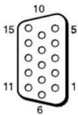
| Pin No. Signal | |
| 1 Red video or C | R/PR |
| 2 Green video or Y | |
| 3 Blue video or C | B/PB |
| 4 Ground | |
| 5 Ground | |
| 6 Red ground | |
| 7 Green ground | |
| 8 Blue ground | |
| 9 Not used | |
| 10 Ground | |
| 11 Ground | |
| 12 SDA | |
| 13 H sync, Composite Video (as sync signal) | |
| 14 V sync | |
| 15 SCL |
Note
When inputting a component signal, be sure not to input sync signals to pins 13 and 14. If you do so, the picture may not be displayed properly.
Index
Numerics
4:3 14,27
A
ACINsocket9,18
Active Picture 25
Address 36
Adjust Screen 20, 27, 28
Advanced 37
Advanced Setup 20, 29
Advertisement 37
All Reset 20, 32
Aspect 20, 27, 28
AUDIO connector 9
AUDIO IN connector 9
Auto Adjustment 28
Auto Screen Adjust 30
Auto Shut Off 30
B
Backlight 21, 23
Balance 22, 24
Bass 22, 24
Brightness 21, 23
Brightness Boost 22, 23
C
Cable holder 19
Chroma 21
CineMotion 21
Clock Display 29
Clock Set 29
Color System 31
Color Temp. 21, 23
Conference 21, 23
Configure screen 35
Contrast 21, 23
Contrast button 13
Control Mode 29
Control screen 35
Control Setting 29
Custom 21, 23
D
DISPLAY button 13
DVI button 12
DVI connector 9
DVI IN connector 9
Dynamic 22, 24
Dynamic Picture 21
E
ECOMode20,29
ENTER button 7
Error Report 36
F
Full 1/Full 2 14, 28
Full 14, 27
G
Gamma Correct. 21, 23
H
H Shift 27, 28
H Size 27, 28
HD15 (RGB/COMPONENT)
connector 9
HD15 (RGB/COMPONENT) IN/
OUT connector 9
HD15 button 13
HDMI button 12
HDMI connector 9
HDMI IN connector 9
1
ID MODE buttons 13, 16
ID Talk 37
Index Number 13, 16, 29
Information 20, 32
Information screen 35
INPUT button 7
Input signal 40
IP Address Setup 31
L
Language 20, 29
LED 27
Logo 31
M
Mail Account 36
Mail Report 36
MENUButton7,12
Multi Display 20, 26, 28
Muting button 13
N
Network 36
Network Port 31
Noise Reduction 21
0
On/Off Timer 29
On-Screen Logo 31
OPTION 1 button 13
OPTION slot 10
Output Format 26
Overscan 30
Owner Information 36
P
PAP 25
PAP button 13, 15
PAP Setting 15, 20, 25, 28
Password 36
Phase 21, 28
PICTURE button 12
Picture Mode Adjust. 20, 21, 23
Picture Mode 20, 21, 23
Picture Position 25
Picture Size 25
Picture/Sound Settings 20, 21
Pitch 28
Position 26
Power On Delay 32
POWER ON switch 12
POWER switch 7
Power/Stand by Indicator 7
R
Real 14, 28
REMOTE connector 9
Remote control sensor 7
Reset 22, 24, 27, 28
RETURN button 7
RGB Signal 31
RGB/YUV 31
s
SVIDEO button 12
SVIDEO IN connector 9
Screen Settings 20, 25
Setup screen 36
Setup Settings 20, 29
Sharpness 21
SNMP 37
Sony logo 7, 31
Sound Mode Adjust. 20, 22, 24
Sound Mode 20, 22, 24
Speaker Out 20, 29
SPEAKER socket 9
Speed Setup 31
Standard 21, 22, 23, 24
STANDBY button 13
Status Display 20, 29
Status Report 36
Surround 22, 24
Swap 25
Sync Mode 30
T
TC Control 21, 23
Tiles 26
Timer Setting 20, 29
Treble 22, 24
TrueColorControl22,23
V
V Shift 27, 28
V Size 28
VIDEO button 12
VIDEO IN/OUT connector 9
VIDEO INPUT 9
Vivid 21, 23
Volume button 13
W
Wide Mode 14
Wide Mode button 12, 14
WideZoom14,27
Window 26
Z
Zoom 14, 27
AVENTISSEMENT
10 Touches ID MODE (OUI/0-9/SET/C/NON)
Touches Brightness + / -
Requires the use of POP Authentication before Send e-mail (POP before SMTP):
Supports de cables (8)
UL), FCC Class B, IC Class B,
EN 60950-1 (NEMKO), CE, C-Tick
Affichage multiple 20, 26, 28
Correct. gamma 21, 23
D
Owner Information (Informations
concernant le propriete) 36
P
PAP 25
Password (Mot de passer) 36
Personalisé 21, 23
Phase 21, 28
Plein ecran 14, 27
Réglage mode image 20, 21, 23
Réglage mode son 20, 22, 24
Réglage PAP 15, 20, 25, 28
Réglages avances 20, 29
Réglages écran 20
Réglages Image/Son 20, 21
Réglages Réglage 20, 29
Réinitialiser 22, 24, 27, 28
Retro-éclairage 21, 23
RGB/YUV 31
s
Signal d'entree 40
Signal RGB 31
SNMP 37
Sortiehaut-p.20,29
Speed Setup 32
Standard 21, 22, 23, 24
Standard couleur 31
Status Report (Rapport d'etat) 36
Surbalayage 30
Surround 22, 24
T
Taille horizontale 27, 28
Taille image 25
Taille verticale 28
TC Control 21, 23
True Color Control 22, 24
Tuiles 26
V
VIDEO INPUT 9
ACHTUNG
Tasten ID MODE (ON/0-9/SET/C/OFF)
Brightness +/-Tasten
Requires the use of POP Authentication before Send c-mail (POP before SMTP):
B,EN 60950-1 (NEMKO), CE, C-Tick
Fenster,Setup" (Setup) 36
Indexnumber 13, 16, 29
Multi-Display 20, 26, 28
N
Password (Kennwort) 36
Phase 21, 28
PICTURE, Taste 12
Pitch 28
Position 26
POWER ON, Schalter 12
POWER, Schalter 7
R
Raumklang 22, 24
Rauschvermind. 21
REMOTE, Anschluss 9
RETURN, Taste 7
RGB/YUV 31
RGB-Signal 31
S
Standard 21, 22, 23, 24
STANDBY, Taste 13
Botones ID MODE (ON/0-9/SET/C/OFF)
Requires the use of POP Authentication before Send e-mail (POP before SMTP):
Estandar 21, 22, 23, 24
F
Fase 21, 28
Formato de salute 26
G
Graves 22, 24
1
ID Talk 37
Idioma 20, 29
Imagen activa 25
Imagen Dinamica 21
Inclinacion 28
Pantalla multiple 20, 26, 28
Pantalla rcloj 29
Restablecer 22, 24, 27, 28
Restablecer todo 20,32
True Color Control 22, 23
V
Ventana 26
VIDEO INPUT 9
Vivido 21, 23
AVVERTENZA
Tasti ID MODE (ON/0-9/SET/C/OFF)
Requires the use of POP Authentication before Send c-mail (POP before SMTP):
NTSC/PAL/PAL-M/PAL-N/
NTSC4.43/PAL60
Segnale di ingresso
Vedere pagina 40.
Passo pixel 0,6 (orizzontale) × 0,6 (vertical) mm
UL), FCC Class B, IC Class B,
EN 60950-1 (NEMKO), CE, C-Tick
Display multiplo 20, 26, 28
Displayora29
E
Modo audio 20, 22, 24
Modo controlo 29
Modo ECO 20, 29
Modo imagine 20, 21, 23
Modosincron.30
N
Network (Rete) 36
Nitidezza 21
Numero indices 13, 16, 29
0
Ripristina 22, 24, 27, 28
Standard 21, 22, 23, 24
Standard colore 31
ID MODE (ON/O-9/SET/C/OFF) 按钮
Sound Mode: (第 21, 23 页)
Sound Mode Adjust. (第 21, 23 页)
Screen
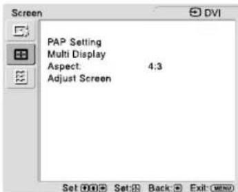
PAP Setting (第 24, 27 页)
Multi Display (第 25, 27 页)
Aspect: (第26,27页)
Adjust Screen (第 26, 27 页)
Setup
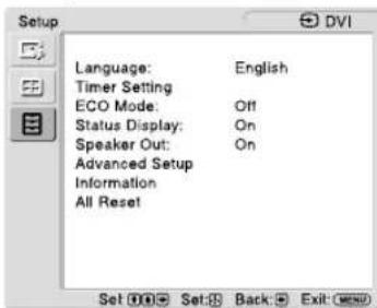
Language: (第28页)
Timer Setting (第 28 页)
ECO Mode: (第28页)
Status Display: (第 28 页)
Speaker Out: (第 28 页)
Advanced Setup (第 28 页)
Information (第30页)
All Reset (第30页)
Requires the use of POP Authentication
before Send e-mail (POP before SMTP):