USER MANUAL CombiCool RC 1600 EGP DOMETIC
natural_image
Line drawing of a rectangular industrial appliance with ventilation grilles and a handle (no text or symbols)
CE
0402
Operating Instructions
Please read these operating instructions carefully before putting the refrigeration unit into operation. If you later sell or dispose of it, please ensure that the new owner receives these operating instructions.
Thank you for choosing our appliance. We are sure it will provide you with trouble-free use.
In the following, we would like to familiarise you with some symbols, which we bring to your attention to ensure the safe and efficient operation of the appliance:

source of danger, in event of improper operation

suggested useful tips to read

information concerning environmental protection
The cooling box you have purchased is designed for operation from electrical mains, from a vehicle battery or from bottled (LP) gas.

Attention!
- Your portable Refrigerator - in gas operation - must only be used in a well-ventilated place, above ground, where it is protected from rain or water splashes.
- In electrical operation, the appliance can be used in an enclosed area. However, the appliance must still be protected from moisture.
- The unit must not be used with gas operation in motor vehicles and boats whilst the vehicle or boat is in motion!
• Operation using liquid gas in enclosed spaces in not permitted!
THIS COOLING UNIT MAY ONLY BE USED WITH GAS OUT OF DOORS!
Outdoor use includes tents (awnings) which are well ventilated throughout unit operation and flat garden terraces.
- In this appliance the storage of any toxic or explosive substance is forbidden!
- Only operate this appliance on one energy source at a time.
- This appliance is not intended for use by persons (including children) with reduced physical, sensory or mental capabilities, or lack of experience and knowledge, unless they have been given supervision or instruction concerning use of the appliance by a person responsible for their safety.
Children should be supervised to ensure that they do not play with the appliance.
- It is important in the interests of efficiency, to give the back of the unit as much ventilation as possible to allow the heat to escape. The hottest spot is in the vicinity of the burner, and particularly when operating on gas, it is essential that this place be kept clear of any obstruction or flammable materials.
CONTENTS
- Unpacking
- View of the appliance
- Cleaning
- Positioning the appliance
- Using the appliance
5.1. From electrical mains
5.2. From vehicle battery
5.3. From bottled gas
-
Ice-making
-
Useful suggestions
-
Defrosting, cleaning and maintenance
-
Customer service
-
Putting into operation, technical data
10.1. Connecting to electrical mains
10.2. Connecting to vehicle battery
10.3. Connecting to as cylinder
10.4. Connection of gas supply
-
Environmental protection information
-
Recycling

ATTENTION!
Warranty arrangements are in accordance with EC Directive 44/19999/CE and the normal conditions applicable in the country concerned.
For warranty or other servicing, such as spare-parts, please contact our Dometic Service Network.
The warranty does not cover any damage due to improper use.
The warranty does not cover any modifications to the appliance or the use of non-original Dometic spareparts.
The warranty does not apply if the installing and operating instructions are not adhered to.
When contacting Dometic Service Network, please state the model, product number and serial number.
You will find this information on the data plate on the rear cover of the refrigerator.
GB
1. Unpacking
After removal from the cardboard packaging, make sure the appliance is not damaged. If you find damage to the appliance resulting from transport, report it immediately to the transportation firm.
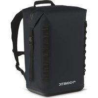
2. View of the appliance
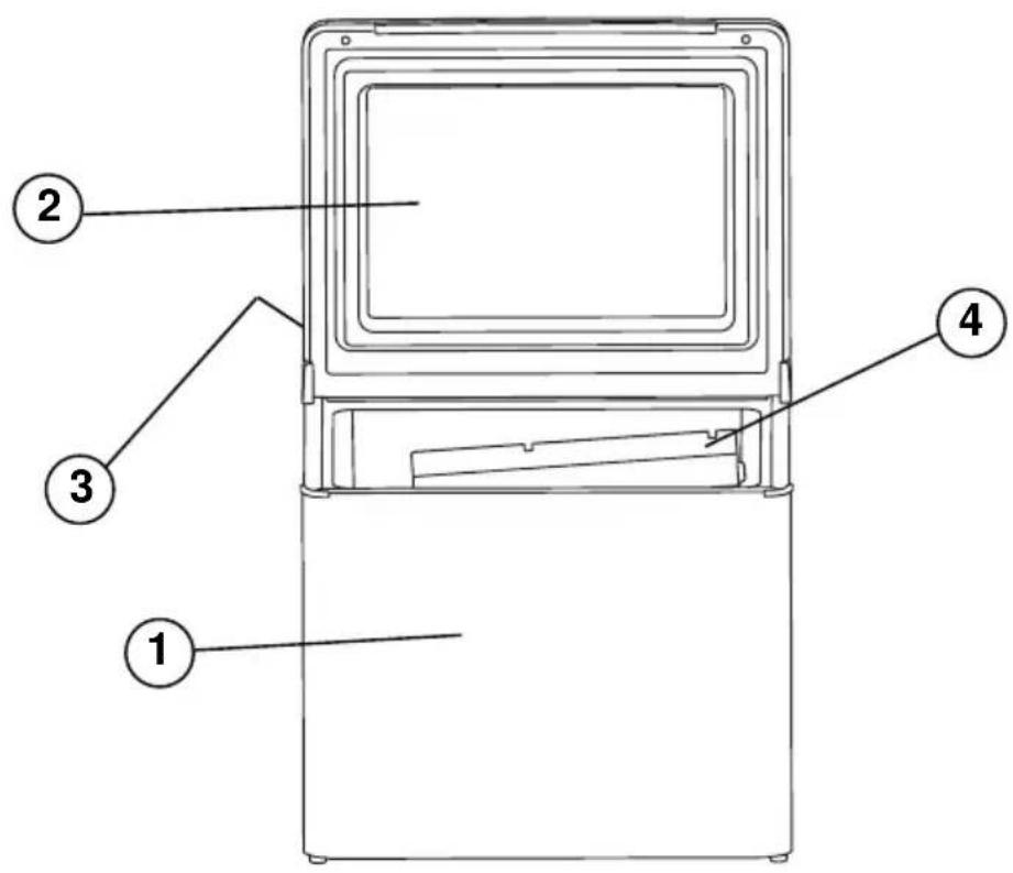
Figure 1.
- insulated casing
-
insulated lid
-
control panel
- evaporator panel
3. Cleaning
i Clean both the inside and outside of the appliance before putting it into use.
- To do so, use a soft towel, lukewarm water and a non-abrasive detergent. Ensure water does not enter the rear cover grille or the control elements.
- Afterwards, wipe the appliance with a clean towel and cleanwater, and then wipe it dry.
- To avoid damage, do not use soap, soda or abrasive cleaners.
4. Positioning the appliance
During the refrigeration process, the appliance gives off heat from the condenser (under the upper part of the rear cover) into the surrounding air.
The more ventilated the condenser is, the more effective the refrigeration will be.
- The other condition for satisfactory operation is that the appliance stands on a flat surface. This is best seen by placing a glass of water on top of the appliance.
- It is important that the appliance is not directly exposed to radiated heat (sunlight, radiator, near an oven, etc.).
- In gas operation following clearances should be kept from the walls or other materials: from the back side of the appliance minimum 10cms, from both sidewalls 4cms each, from the top of the appliance minimum 30 cms, from the bottom minimum 5 cms.
- In the immediate vicinity of the appliance within the specified distances no inflammable matters (paper, wood, grass, textile etc.) should be met with.
5. Using the appliance
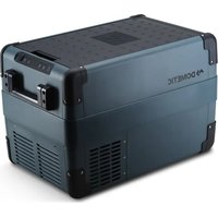
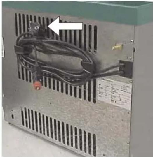
The cable for mains connection, the 12V connecting cable and the connector for the gas hook-up are located on the rear cover of the cooling box. (Figure 2).
5.1. Operating from electrical mains
Make sure the voltage shown on the data plate of the appliance matches that of the mains voltage to which you wish to connect the appliance. Pull out the mains connecting cable and connect it to a receptacle earthed socket for connection.
When connecting the appliance for the first time, set the thermostat (Figure 4. A), to maximum; then, after about five hours, set it back towards minimum according to your need of cooling.
NB: Plug is provided according to specific regulations in each country and may be different to that shown.
natural_image
Close-up of an industrial power supply unit with visible circuit breakers and wiring, no text or symbols present.
Figure 2.
GB
5.2. Operating from vehicle battery
Make sure the voltage shown on the data plate of the appliance matches the voltage of the vehicle battery (12V or 24V).
12V DC voltage appliances are equipped with connectors that can be plugged into cigarette lighters (Figure 3.). For some types of vehicles, you may need to remove the red plastic ring located on the end of the connector. To do so, turn the plastic ring anticlockwise and pull it off. The appliance can then be connected to the cigarette lighter. In 12V operation, the appliance runs uninterrupted without temperature control.
24V DC voltage appliances are shipped with bare wire ends. The wire ends must be connected to a terminal block, which is connected to the vehicle battery via a 5A fuse and 5A switch.
Whenever the engine is not running, the appliance connector must be removed from the cigarette lighter (12V appliance) or the switch turned off (24V appliance). Otherwise, the appliance will discharge the vehicle battery rapidly.
5.3. Operating from bottled gas
Connection to the gas cylinder is described in sections 9.3. and 9.4.
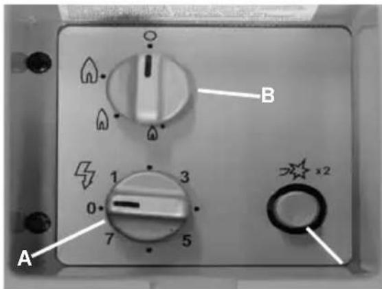
After opening the valve of the gas cylinder and checking for gas leaks turn thermostat to maximum position (Figure 4. B), press down the gas safety valve hold it down for about 10 seconds and then, press the piezo-ignition button (marked with a star Figure 4. C) several times in quick succession. If the flame does not ignite, repeat the process. (Air in the appliance gas line prior to connection to the gas cylinder must be purged. Only then can the gas be lit.).
The control knob has 4 positions:
: high flame (MAX) = gas supply maximum (high ambient temperature \~32 °C);
: medium flame (MID)= gas supply medium (normal ambient temperature \~ 25°C);
: low flame (MIN) = gas supply minimum (low ambient temperature \~ 16°C);
● : off-position = gas supply to burner is shut off.
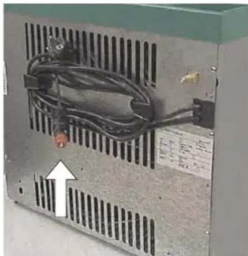
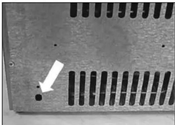
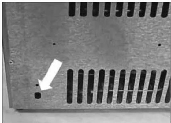
Ignition of the flame can be verified through the flameview opening (Figure 5). After you have the flame alight keep the safety gas valve pressed down for a further 20 seconds.
To stop the gas operation the valve of the gas cylinder (or the pressure regulator) is to close.
natural_image
Close-up of an industrial electrical enclosure with visible wiring and ventilation grilles (no text or symbols)
Figure 3.
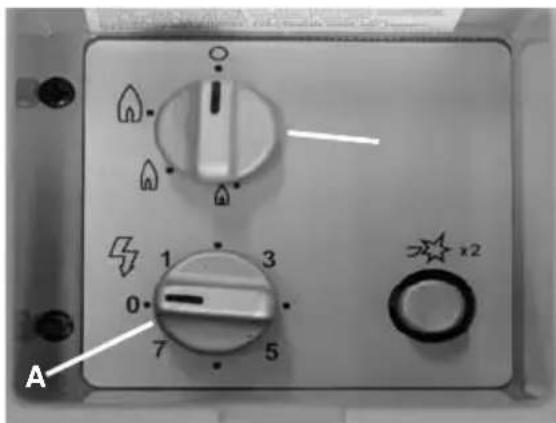
Figure 4.

natural_image
Close-up of a metallic panel with perforated edges and a white arrow pointing to a small dot (no text or symbols)
Figure 5.
6. Ice-making
Fill the ice-tray with drinking water to within 4/5 from the top and cover with lid. Wipe off any drops of water which may be on the tray and lid to prevent freezing together and place in the cooler on the refrigerating unit.
Ice will be made more quickly when the thermostat knob (for electric operation) or regulating knob (for liquid gas operation) is set to MAX for a short time. (When ice has formed, do not forget to return the knob to its normal setting.)
To remove the ice, allow the ice-tray to defrost slightly for a while or run it under tap water at normal temperature before removing the lid from the tray. The ice cubes can now be removed easily from the tray.
i 7. Useful suggestions
- When setting out on a trip, run the appliance on 230 V (in thermostat setting between "min" and "max") for 24 hours prior to departure. Place food in a precooled condition into the appliance.
- Frost forms on the evaporator panel when in operation. When opening the lid or putting in food, some of this frost melts and collects in the form of water on the bottom of the appliance. Wipe the water off occasionally using a sponge.
- Avoid putting foods with fragile packaging (such as glass) into the cooling box. Movements and shaking of the unit may cause these items to break.
- Once the coolong box is in its permanent position, make sure foods do not come into contact with the evaporator panel, as this can cause freezer-burn to the foods.
8. Defrosting, cleaning and maintenance
For defrosting, always unplug the appliance from an electrical power source to avoid the risk of shock.
Make sure no other power source is connected (gas or 12V/24V). Remove food from the refrigeration unit and leave the lid open. Depending on the temperature, frost melts in a short time from the evaporator panel, with water collecting at the bottom of the appliance.
Wipe it off using a towel. Afterwards, clean the appliance by following the instructions in section 3.
Leave the lid ajar to prevent any odours from forming.
The appliance does not require any further maintenance.
GB
9. Customer service
Before notifying customer service, please check the following:
- Are location and ventilation satisfactory?
• Is the appliance level?
- Is there a current in the wall socket and is the connection suitable for the appliance?
• Is the mains power cable damaged?
- For mains operation, is the electric thermostat switched on?
- For gas operation, was the safety valve knob pressed down long enough?
- Is the thermostat knob set towards the maximum position?
• Is the gas cylinder or the pressure regulator valve open?
- Is there any gas in the cylinder? (If by shaking, no liquid movement can be detected, then the cylinder is empty.)
- Are by any chance two different power sources connected (such as gas or electricity)?
• Was warm food placed in the unit?
• Was a large quantity of food put in at one time?
If after checking the above, the appliance still does not operate properly, contact customer service.
When reporting the problem, state the type of problem, the type of appliance, and the product number and serial number from the data plate.
We assume the warranty in accordance with our warranty assumptions for the appliance.
www.dometic.com
10. Putting into operation
You must, in all instances, operate the appliance from a single energy source only. Connecting several energy sources at the same time will cause failure of the appliance.
Technical data:
| Model RC 1200 EGP RC 1600 EGPRC 1700 EGPRC 2200 EGP | |
| Type JCB - 1 JCB - 1 | | |
| Gross volume 41 litre 33 litre | |
| Mains operation 220 - 240V (AC) 220 - 240V (AC) |
| Input 85W 75W | |
| Energy consumption | 1.38 kWh/24h | 1.35 kWh/24h |
| Battery operation | 12V (DC) | 12V (DC) | 24V (DC) |
| Input 85W 75W 65W | | | |
| Energy consumption | 170Ah/24h | 150Ah/24h | 65Ah/24h |
| Gas pressure (p) | 28-30/37 mbar | 28-30/37 mbar |
| Gas classification | I_3+ | I_3+ |
| Jet size | 2 | 2 |
| Rated thermal loading: butane(propane) | 134W - 9,8 g/h 134W(118W - 8,4g/h) | -9,8 g/h(118W - 8,4g/h) |
| Min.thermal loading: butane(propane) | 106W - 7,7g/h(86W - 6,1g/h) (86W - 6,1g/h) | 106W - 7,7g/hW - 6,1g/h) |
| Climate class | N | N |
| Refrigerant | 143g H_2O + 67g NH_3 | 143g H_2O + 67g NH_3 |
10.1. Connecting to electrical mains
Make sure no other energy source is connected (gas, 12V).
The appliance may only be operated from nominal voltage mains as shown on the data plate. The appliance mains plug may be connected to a mains socket earthed in accordance with regulations.
Any electrical work required to install this appliance should be carried out by a qualified electrician or competent person.
The manufacturer declines any liability should these safety measures not be observed.
Electrical Requirements
Before switching on, make sure the electricity supply voltage is the same as that indicated on the appliance data plate.
Only for UK:
The appliance is supplied with a 3 amp plug fitted. In the event of having to change the fuse in the plug supplied, a 3 amp ASTA approved (BS 1362) fuse must be used. Should the plug need to be replaced for any reason, the wires in the mains lead are coloured in accordance with the following code:
Green and Yellow: Earth
Blue: Neutral
Brown: Live
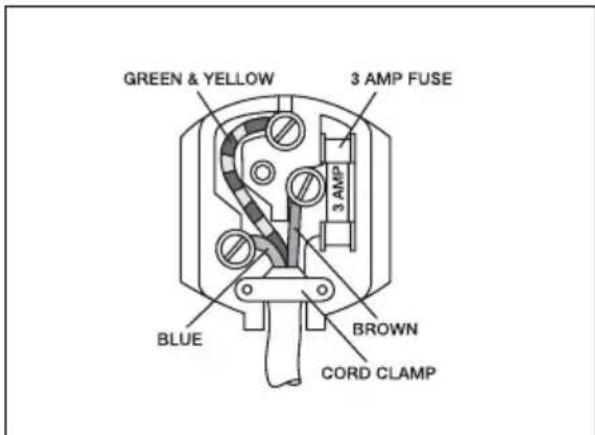
The wire coloured green and yellow must be connected to the terminal marked with the letter „E“ or by the earth symbol or coloured green and yellow.
The wire coloured blue must be connected to the terminal „N“ or coloured black.
The wire coloured brown must be connected to the terminal marked „L“ or coloured red.
Upon completion there must be no cut, or stray strands of wire present and the cord clamp must be secure over the outer sheath.
10.2. Connecting to vehicle power source
Make sure no other energy source is connected (gas, 230V).
A safety fuse must be installed in the electricity supply between battery and the cooling box in a duct.
12V appliances must be connected to a vehicle cigarette lighter, which is protected with a 10A fuse.
24V appliances must be connected by inserting a terminal block and switch and protected with a 5A fuse. The switch must be suitable for switching a 5A current.
It is not necessary to consider the polarity when connecting the unit.
In case you need a longer cable, please refer to the table below:
max. cable lengths
| Cable cross section 12 V 24 V | |
| 2.5 mm^2 | until 2.5 m 5 m | |
| 4.0 mm^2 | until 4.0 m 8 m | |
| 6.0 mm^2 | until 6.0 m 12 m | |
Do not connect a cable thicker than 2.5 mm ^4 into the cigarette lighter plug! Please build a terminal block connection.
10.3. Connecting to gas cylinder
Make sure no other energy source is connected (230V, 12V).
The unit must not be connected to town or natural gas pipelines. It is only suitable for use with propane/butane gas (e.g. Calor Gas, Camping Gaz, Caravangas, etc.).
The cooling box is equipped for a specific gas-pressure, corresponding to the standard pressure of the country in which it is sold. The data plate states the pressure that is correct. It is important that a non-adjustable pressure-regulator must be used to reduce the pressure in the gas cylinder to the operating pressure specified on the data plate. No other pressure may be used.
Needle valve-operated gas valves are NOT suitable for use with this appliance and must not be used as a substitute for a pressure regulator.
10.4. Connection of gas supply
(The following instructions refer in the main to coolers manufactured in the United Kingdom. For other countries please refer to your supplier.)
Always connect in the following sequence:
$$
\begin{array}{l}\text { GAS BOTTLE } \rightarrow \text { PRESSURE - REGULATOR } \rightarrow\\rightarrow \text { APPLIANCE. }\end{array}
$$
To connect the appliance to the pressure-regulator an APPROVED FLEIBLE GAS TUBE must be used. This must not be longer than 1,5 m - and should have an inside dimension of 8 mm and be marked BS3212/2/8. The flexible gas tube must not be twisted! It must be regularly changed if it is determined in the standard of your country.
The pressure-regulator must be compatible for Butane 11 in (28 mbar) or for Propane 14 in (37 mbar).
To connect the pressure-regulator to the gas bottle, the valve of the gas bottle must be closed. After connecting the pressure regulator to the bottle by screwing, connect the two ends of the tubing to the nipples and secure them with the two hose clipse. (Figure 6).
When fitting the connection to the gas inlet of the appliance (Figure 6 D), hold the counterpart to avoid straining and possibly damaging.
The gas bottle (Butane, blue bottle) may only be used in an upright position and particular care must be taken every time the appliance is connected to the gas bottle to ensure that there are no leaks, that the tubing (rubber hose) is not under tension or kinked, and that it is not in contact with hot surfaces.
The tubing and the gas bottle should always be located in positions where they will not be tripped over or otherwise inadvertently disturbed.
Before attempting to light the burner, every time after connection, turn on the gas at the bottle and check the gas connections for leaks by applying a soap and water solution over them and watching for bubbles, which would indicate a leak.
After testing dry off traces of detergent.
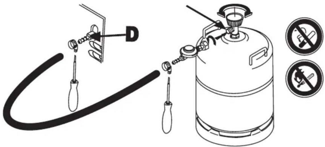
Figure 6.

For your safety:
Do not check for leaks with a naked flame!
Do not smoke while checking for leaks!

The appliance does not contain any CFCs/HCFCs.
Ammonia (natural hydrogen and nitrogen compound) is used as refrigerant agent in the cooling unit.
The ozone-friendly cyclopentane is used as a blowing agent for the PU foam insulation.
Sodium chromate is used for corrosion protection (less than 2 weight % of the coolant).

12. Recycling
After unpacking the appliance, the packing materials should be delivered to a local collection site. At the end of its useful lifetime, the appliance should be delivered to a specialised recycling firm, which reclaims the usable materials. The rest is properly destroyed.
Appliances bearing this symbol must be deposited at the designated local reception point for the disposal of electrical and electronic equipment.
It is not permitted that this product be disposed of by way of the normal household refuse collection system.
Dometic refrigerators bear this symbol on the specifications plate (data plate) to be found on the rear cover of the unit.
This appliance complies with the following EEC directives:
LVD-Directive 2006/95/EC
EMC-Directive 2004/108/EC
Gas-Directive 90/396/EEC
CE-Directive 93/68/EEC
RoHS-Directive 2002/95/EC
WEEE-Directive 2002/96/EC.

natural_image
Interior view of an industrial electrical enclosure with visible wiring and ventilation grilles (no text or symbols)
Figure 2
natural_image
Interior view of an industrial electrical enclosure with visible wiring and ventilation grilles (no text or symbols)
Figure 3

Figure 4

natural_image
Close-up of a metallic panel with vertical slots and a white arrow pointing to a small dot (no text or symbols)
Figure 5
FR
6. Fabrication de glaçons
Figure 7

Directive LVD 2006/95/CE
Directive EMC 2004/108/CE
Directive relative au gaz 90/396/CEE
Directive CE 93/68/CEE
Directive RoHS 2002/95/CE
Directive WEEE 2002/96/CE

natural_image
Close-up of an industrial electrical enclosure with visible wiring and ventilation grilles (no text or symbols)
Figura 2
IT
natural_image
Close-up of an industrial electrical panel with visible wiring and ventilation slots (no text or symbols)
Figura 3

Figura 4.
natural_image
Close-up of a metallic panel with perforated slots and a white arrow pointing to a small dot (no text or symbols)
Figura 5.
Figura 9.

Afbeelding 1.
natural_image
Close-up of an industrial power supply unit with visible circuit breakers and a white arrow pointing to a component (no text or symbols)
Afbeelding 2
NL
natural_image
Close-up of an industrial power supply unit with visible wiring and a white arrow pointing to a component (no text or symbols)
Figure 3
Afbeelding 4.

natural_image
Close-up of a metallic panel with vertical slots and a white arrow pointing to a small dark spot (no text or symbols)
Afbeelding 5.
natural_image
Close-up of a hand holding a white cable with a metallic connector, next to a white panel on a perforated metal panel (no visible text or symbols)
Afbeelding 10.

EEN DICHTHEIDSCONTROLE MET OPEN VLAM IS NIET TOEGESTAAN!
NIET ROKEN! EXPLOSIE- EN VERBRANDINGSGEVAAR!
Figure 1.
natural_image
Close-up of an industrial electrical enclosure with visible wiring and ventilation grilles (no text or symbols)
Figure 2
ES
natural_image
Close-up of an electrical power supply unit with visible circuit breakers and wiring (no text or symbols)
Figure 3
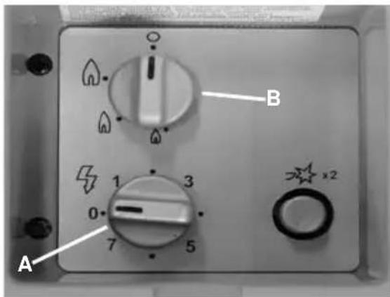
Figure 4.
natural_image
Close-up of a metallic panel with vertical slots and a white arrow pointing to a small dot (no text or symbols)
Figure 5.
Figure 9.