Butler 5750 - Phone TOPCOM - Free user manual and instructions
Find the device manual for free Butler 5750 TOPCOM in PDF.

| Features | Details |
|---|---|
| Phone type | DECT cordless phone |
| Display | Backlit LCD screen |
| Standby time | Up to 100 hours |
| Talk time | Up to 10 hours |
| Range | Up to 300 meters outdoors, 50 meters indoors |
| Additional features | Built-in answering machine, caller ID, customizable ringtones |
| Maintenance | Clean with a soft cloth, avoid chemical products |
| Security | DECT communication encryption, protection against unwanted calls |
| Dimensions | Compact dimensions for easy storage |
| Weight | Lightweight, easy to handle |
| Warranty | 2 years |
Frequently Asked Questions - Butler 5750 TOPCOM
User questions about Butler 5750 TOPCOM
0 question about this device. Answer the ones you know or ask your own.
Ask a new question about this device
Download the instructions for your Phone in PDF format for free! Find your manual Butler 5750 - TOPCOM and take your electronic device back in hand. On this page are published all the documents necessary for the use of your device. Butler 5750 by TOPCOM.
USER MANUAL Butler 5750 TOPCOM
To use ‘Caller ID’ (display caller), this service has to be activated on your phone line. Normally you need a separate subscription from your telephone company to activate this function. If you don’t have the Caller ID function on your phone line, the incoming telephone numbers will NOT be shown on the display of your telephone.
Belangrijk
UK To be connected to the public analogue telephone network.
UK The features described in this manual are published with reservation to modifications.
This product is in compliance with the essential requirements and other relevant provisions of the R&TTE directive 1999/5/EC.
The Declaration of conformity can be found on:
http://www.topcom.net/support/cedeclarations.php
UK The CE symbol indicates that the unit complies with the essential requirements of the R&TTE directive.
1 Safety instructions .... 1
2 Getting started ....1
2.1 How to use this user guide.... 1
2.2 Installing the base.... 1
2.3 Installing the handset.... 2
2.4 Keys/Led....3
2.5 Symbols 3
2.6 Display keys 4
2.7 Base LED....4
2.8 Navigating the menu....4
2.9 Menu overview 4
3 Using the telephone....5
3.1 Switching the handset ON/OFF 5
3.2 Changing the menu language 5
3.3 Making a normal telephone call 6
3.4 Receiving a telephone call....6
3.5 Handsfree mode....7
3.6 Adjust earpiece/handsfree volume 7
3.7 Secrecy function (Mute function).... 7
3.8 Locating a handset (Paging function)....7
3.9 Keypad Lock 7
3.10 Using the alphanumerical keypad 7
4 Phonebook....8
4.1 To add an entry 8
4.2 To dial an entry....8
4.3 Show Details....8
4.4 Delete an entry or all entries....9
4.5 Edit name and number....9
4.6 Copy a phonebook entry to another handset 9
4.7 Copy all phonebook entries to another handset.... 10
5 Caller Identification....10
5.1 Normal incoming PSTN calls.... 10
6 Personalise the handset 11
6.1 Ringtone and volume.... 11
6.2 Handset name 11
6.3 Keypad beeps.... 12
6.4 Setting the contrast 12
6.5 Autotalk 12
6.6 Setting the display backlight Time....12
6.7 Prefix code.... 12
6.8 Using the alarm feature 13
6.9 Setting the date and time 13
6.10 Setting the time format 13
7 Base settings 14
7.1 Ringtone 14
7.2 Ringer Volume 14
7.3 Dial Mode....14
7.4 Recall (Flash).... 14
7.5 System PIN 15
8 Tools....15
8.1 Appointment.... 15
8.2 Stopwatch 16
9 Additional handsets and base stations....16
9.1 Adding a new handset 16
9.2 Removing a handset 16
9.3 Select a base 17
9.4 Using the intercom feature 17
10 Answering machine 18
10.1 Display.... 18
10.2 Outgoing Messages 18
10.3 Turning Answering Machine On/Off 20
10.4 Setting number of Rings (Answer delay) 20
10.5 Programming the VIP Code 20
10.6 Operation 21
10.7 Call Screening 21
10.8 Recording a Memo 21
10.9 Playback of Incoming Messages and Memos 21
10.10 Erasing Messages 22
10.11 Memory Full 22
10.12 Remote Operation.... 22
10.13 Turning answering machine on remotely 23
11 Troubleshooting....24
12 Technical data Technical characteristics....25
13 Warranty 25
13.1 Warranty period.... 25
13.2 Warranty handling.... 25
13.3 Warranty exclusions 25
14 Disposal of the device (environment) 26
15 Cleaning....26
16 ECO (low-radiation) mode....26
Nederlands 27
1 Safety instructions
- Only use the charger plug supplied. Do not use other chargers as this may damage the battery cells.
- Only insert rechargeable batteries of the same type. Never use ordinary, non-rechargeable batteries. Insert rechargeable batteries so they connect to the right poles (indicated in the battery compartment of the handset).
- Do not touch the charger and plug contacts with sharp or metal objects.
- The operations of some medical devices may be affected.
- The handset may cause an unpleasant buzzing sound in hearing aids.
- Do not place the basic unit in a damp room or at a distance of less then 1.5m away from a water source. Keep water away from the handset.
- Do not use the telephone in environments where there is a risk of explosions.
- Dispose of the batteries and maintain the telephone in an environment-friendly manner.
- As this telephone cannot be used in case of a power cut, you should use a mains-independent telephone for emergency calls, e.g. a mobile phone.
2 Getting started
2.1 How to use this user guide
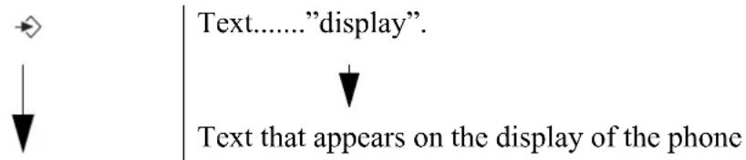
In this user guide, following method is used to clarify the instructions:
text_image
Text......"display". ↓ Text that appears on the display of the phoneKey to press. This key can be a soft key (See "2.4 Keys/Led"). When the soft key is a symbol, it is shown in the left column. When the soft key is text, the left or right soft key is shown in the left column and the text is shown in the right column between quotation marks.
2.2 Installing the base
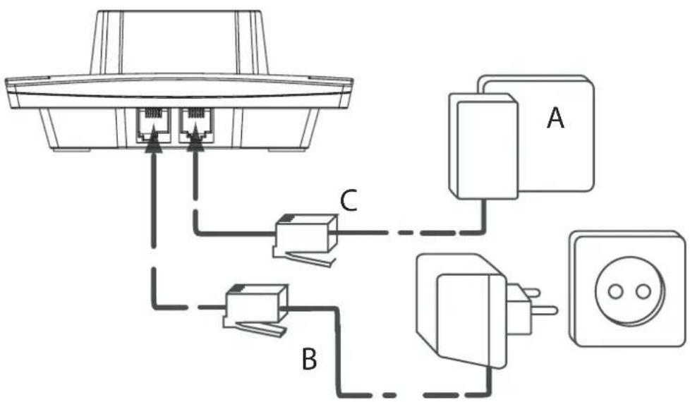
For installation, do the following:
1 Plug one end of the adaptor into the outlet and the other end into the adaptor jack on the back of the base.
2 Connect one end of the telephone cord with the wall phone jack and the other end to the bottom of the base.
3Put the telephone- and AC power line cord in the base guides as shown on picture 2A.
text_image
Electrical wiring diagram showing connections between a device, switches, and power outlet with labeled components A, B, and C.- 2A Back view of base -
A. Telephone wall outlet
B. Power cable
C. Telephone cord
2.3 Installing the handset
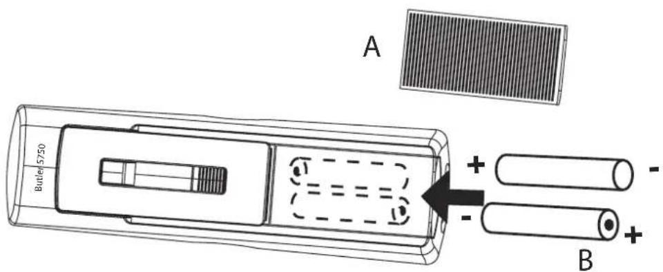
1Open the battery compartment as shown on picture 2B.
2Insert the batteries respecting the polarity (+ and -).
3Close the battery compartment.
4Leave the handset on the base unit for 20 hours. The Line/Charge indicator 📞 on the base will light up.
text_image
A 5750 Butler + - B +- 2B Back view of handset -
A. Cover
B. Rechargeable batteries

Before you use the telephone for the first time, you must first make sure the battery is charged for 20 hours. If you do not do this, the telephone will not work optimally.
2.4 Keys/Led
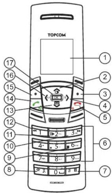
Handset
- Display
- Up/Redial key
- Right soft menu key
- Right/Flash key
- On-hook / OFF key
- Alphanumeric keys
- Keypad lock
- Ringer Off-key
- Stop Key
- Skip forward key
- Play/Pause key
- Skip backwards
- Down/call log key
- Off-hook key/ Handsfree/ On-key
- Left soft menu key
- Left/INT key
- OK key
text_image
TOPCOM 17 16 15 14 13 12 11 10 9 8 1 2 3 4 5 6 7 8 9 * X 0 # H ① ② ③ ④ ⑤ ⑥ ⑦- 2C Handset -
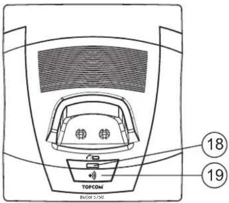
Base
- In use/Power/Handset on base LED
- Paging key
text_image
TOFCOM Builder 2/30 18 19- 2D Base -
2.5 Symbols
Off hook Keypad lock
On hook Alarm set
Missed calls in call list* Handset not registered or out of range
Handset ringer volume OFF Battery empty
Y Handset within base range Battery low
Internall Call Battery medium
Handsfree Battery full
New voice mail Answering machine On/Off/


* If the Caller line identification service is available on the telephone line.
2.6 Display keys
Display-keys (softkeys) are located directly under the display. The function of these 2 keys changes depending on the operation mode. The actual function is displayed as icon or text directly above the 2 display keys.
| ∅ | Phonebook Mute | |
| ✓ | OK/Confirm Back | |
| → | Menu No key | |
| ◀ | Delete Play messages |
2.7 Base LED
The LED (14) indicates the following status:
• OFF: no base power connected or handset not in base for charging
• ON: handset charging
- Blinking slowly: Off hook or during ringing
- Blinking rapidly: during registration
2.8 Navigating the menu
The Butler 5750 has a menu system which is easy to use. Each menu leads to a list of options. The menu map is shown on the following paragraph.

1 When the handset is switched on and in standby, press the left soft menu key to open the main menu.
2Scroll to the desired menu option.
3Press the soft menu key to view further options or to confirm the setting displayed.
To exit or to go back one level in the menu

To go to the previous level in the menu, press the soft menu key. To cancel and return to standby at any time, press the on-hook key.
2.9 Menu overview
| Menu Submenu items | |
| Ans Machine | Play MsgsDelete MsgsAns On/OffRecord MemoOutgoing MsgAns Settings |
Phonebook
| Menu Submenu items | |
| Handset | Ringtone |
| Ringer Volume | |
| Handset Name | |
| Keypad Beep | |
| Contrast | |
| Auto Talk | |
| Backlight Time | |
| Prefix | |
| Select Base | |
| Language | |
| Registration | |
| Base settings | Ringtone |
| Ringer volume | |
| Dial mode | |
| Recall | |
| System PIN | |
| Time | Set Alarm |
| Date and Time | |
| Set Time Format | |
| Tools | Appointment |
| Stop watch | |
3 Using the telephone
3.1 Switching the handset ON/OFF


1Press and hold the OFF key to switch the handset off.
2Press the off-hook key or place the handset in the base to switch the handset back on.
3.2 Changing the menu language


1Enter the menu.
2Select "Handset" and confirm.
3Select "Language" and confirm.
4Select a language and confirm.
The screen displays "Saved".
5Press the on-hook key to return to standby.

The arrows indicate that further options are available in the menu.
3.3 Making a normal telephone call
Direct dialling
1Press the off-hook key to start the call.
2Dial the telephone number.
3Press the on-hook key to hang up or put the handset back on the base.
Pre-dialling
With the pre-dialling feature, you can enter and modify a number before making the call.
1Dial a number of up to 24 digits.
Press and hold the 0 key to insert a pause. The screen displays a "P".
2Press the soft menu key to correct.
3Press the off-hook key to start the call.
4Press the on-hook key to hang up or put the handset back on the base.
Redial a number from the list
You can redial up to 10 of the last numbers called. If you have stored a name in the phonebook to go with the number, the name will be displayed instead.


1Press the redial key.
2Select a number. If the number is in the phonebook, the name will be shown.
3Press the off-hook key to start the call or select "Option".
4If you selected "Option", scroll and select:
"Delete Call": to remove the number from the call list;
"Save Number": to store the number into the phonebook;
"Delete All": to erase the call list.

5Confirm selection.
6Press the on-hook key to return to standby.
3.4 Receiving a telephone call
When you receive an external call, the screen displays "External Call".
To take the call:

1Press the off-hook key.
OR
Lift the handset off its base if you have activated "Auto Talk"
(See "6.5 Autotalk")
The call in progress icon 🔔 appears on the screen. The call duration is displayed after 15 seconds.
2Press the on-hook key to hang up or put the handset back on the base.


You can turn the ring volume off during incoming call by selecting "Quiet".
3.5 Handsfree mode
Handsfree lets you talk to your caller without holding the handset. It also enables other people in the room to listen to both sides of your conversation.

1To switch any call to handsfree, press the handsfree key during the call.
3.6 Adjust earpiece/handsfree volume

1Press up or down to select volume 1-5 during a normal or handsfree call.
3.7 Secrecy function (Mute function)
To turn off the microphone so the person on the other side of the line will not hear you.

1 During a conversation, press the soft menu key to deactivate the microphone.
“Mute On” appears on the display.
2Select "Off" to activate the microphone again.
3.8 Locating a handset (Paging function)
1Press the paging key on the base. All handsets registered with the base will ring for 30 seconds.
2Press any key on the handset to stop the paging.
3.9 Keypad Lock
To lock the keypad to prevent accidental dialling while carrying the handset around. In standby:

1Press and hold the keypad locked key (key 7 - Picture 2C) until "Locked" and the keypad locked icon appears on the display.

2To unlock, select "Unlock", followed by the keypad locked key.
3.10 Using the alphanumerical keypad
With your telephone, you can also enter alphanumeric characters. This is useful for entering a name into the phonebook, giving a name to the handset, ...
To select a letter, press the corresponding key as many times as necessary.
For example, to select an 'A', press '2' once. To select a 'B', press '2' twice and so on.
To select ‘A’ and then ‘B’ consecutively, press ‘2’ once, wait until the cursor moves on to the next character, then press ‘2’ twice.
During entering text, the available character under each key appears below on the display.
You can change the input character set from English (abc) to Latin (aàá), Greek (ABΓ) or Russian (AßB) by pressing and holding the #-key for 2 seconds.
| ─ | Press ‘0’ to select a space. |
| * | Press the *-key to switch between small letters and capitals. |
| # | Press and hold the #-key for 2 seconds to change the input character set. |
| ◀ | Press the soft menu key to correct. |
4 Phonebook
Each handset can store up to 200 names and numbers. Names can be up to 16 characters long and numbers up to 24 digits.
4.1 To add an entry
| 1Press the soft menu key. | |
| If the phonebook is empty, “Phonebook Empty” appears on the display. If names have been stored, they are listed. | |
| 2Select “Option”. | |
| ^√ | 3Select “New Entry” and confirm. |
| 4.56 | 4Use the keypad to enter the name, then select “Save”. |
| 4.56 | 5Use the keypad to enter the number, then select “Save”. |
| ^√ | 6Select the desired ring melody and select “Save”. |
| 7Return to standby. |
4.2 To dial an entry
| ▽ | 1Press the soft menu key. |
| ▽▽ | 2 Select the desired name or use the keypad to enter the first letter of the name. |
| 3Press the off-hook key to start the call. | |
| 4Return to standby. |
4.3 Show Details
| ▽ | 1Press the soft menu key. |
| ^▽ | 2 Select the desired name or use the keypad to enter the first letter of the name. |
| ▽ | 3Select “Option”. |
| ^▽ | 4Select “Show Details” and confirm. |
| The name, number and ring melody you have assigned to the entry appear on the display. | |
| 5Return to standby. |
4.4 Delete an entry or all entries
| ▽ | 1Press the soft menu key. |
| ^▽ | 2 Select the desired name or use the keypad to enter the first letter of the name. |
| ▽ | 3Select “Option”.To delete one entry: |
| ^▽ | 4Select “Delete Entry” and confirm.To delete all entries: |
| ^▽ | 4Select “Delete All” and confirm. |
| × | 5Press the left menu key to cancel or the right menu key to confirm. |
| 6Return to standby. |
4.5 Edit name and number
| ▽ | 1Press the soft menu key. |
| ^▽ | 2 Select the desired name or use the keypad to enter the first letter of the name. |
| ▽ | 3Select “Option”. |
| ^▽ | 4Select “Edit Entry” and confirm. |
| ▽ | 5Press the soft menu key to delete and use the keypad to change the name. |
| ▽ | 6Select “Save”. |
| ▽ | 7Edit the number and select “Save”. |
| ^▽ | 8Select the desired ring melody and select “Save”. |
| ▽ | 9Return to standby. |
4.6 Copy a phonebook entry to another handset
| ▽ | 1Press the soft menu key. | |
| ▽▽ | 2 Select the desired name or use the keypad to enter the first letter of the name. | |
| ▽ | 3Select “Option”. | |
| ▽▽ | ▽ | 4Select “Copy Entry” and confirm.The available handsets (all the handsets that are registered on the base) are shown. |
| ▽▽ | ▽ | 5Select the desired handset and confirm.“Copying to handset x” appears on the display.“Receive phonebook record?” appears on the display of the destination handset. |
| × | ▽ | 6On the destination handset, press the right menu key to confirm or the left menu key to cancel the transfer. |
| ▽ | 7Return to standby. |
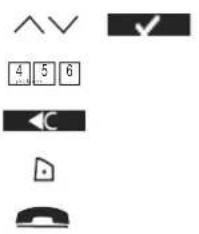
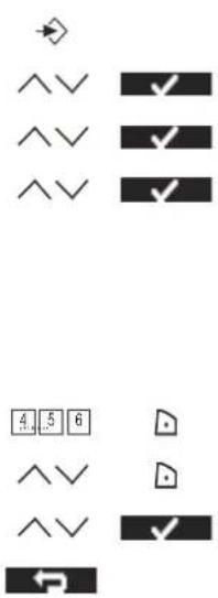
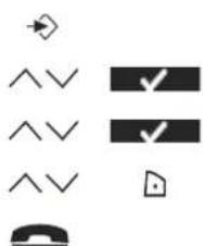
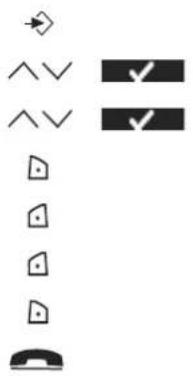
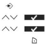
4.7 Copy all phonebook entries to another handset

By copying all entries from one handset to another, you will erase all existing records at the destination handset.
text_image
Image containing four symbols: a checkmark, a double arrow, a triangle, and a checkmark with a checkmark.1Press the soft menu key.
2 Select the desired name or use the keypad to enter the first letter of the name.
3Select "Option".
4Select "Copy All" and confirm.
The available handsets (all the handsets that are registered on the base) are shown.
5Select the desired handset and confirm.
"Copying to handset x" appears on the display.
"Replace all phonebook records?" appears on the display of the destination handset.
6On the destination handset, press the right menu key to confirm or the left menu key to cancel the transfer.
7 Return to standby.

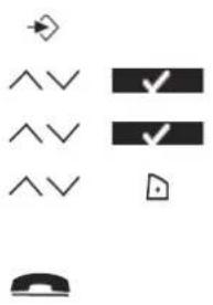
5 Caller Identification
5.1 Normal incoming PSTN calls

This service only works when you have a Caller ID/Clip subscription. Please contact your telephone company.
When you receive a call from your fixed telephone line, the telephone number of the caller appears on the handset display. The telephone can receive calls in both FSK and DTMF. You can also see his or her name if it is transmitted by the network. If the name is programmed in the phonebook, the name in the phonebook is displayed!
The telephone can store 30 calls in a Call List (received and missed) that can be reviewed later. When the memory is full, the new calls automatically replace the oldest calls in the memory.

Missed calls are signalled by a blinking icon on the display. The handset name is replaced by this icon and the amount of missed calls.
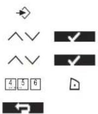
To read the received calls

1Press the down button. The Received calls list appears on the display. This is a combination of received and missed calls.
2Select the desired name or number.
3Press the off-hook key to start the call. OR
Select "Option".
To delete one entry:
text_image
^^ ← ^^ → ^^ → ^^ → ^^ →4Select "Delete Call" and confirm.
5Return to standby.
To delete all entries:
5Select "Delete All" and confirm.
6Return to standby.
To add the number to the phonebook:
5Select "Save Number" and confirm.
6Use the keypad to enter the name, then select "Save".
7Use the keypad to edit the number, then select "Save".
8Select the desired ring melody end select "Save".
9Return to standby.
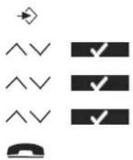
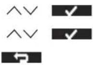
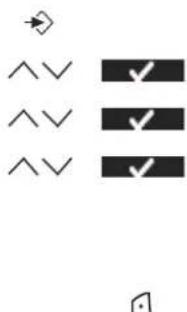
6 Personalise the handset
6.1 Ringtone and volume
Ringtone
You can choose from 18 different ringer melodies for internal and external calls.
text_image
Diagram showing directional arrows and checkmarks on a vertical bar layout, with a telephone icon below.1Enter the menu.
2Select "Handset" and confirm.
3Select "Ringtone" and confirm.
4 Select "External" for external calls or select "Internal for internal calls and confirm.
5Select the desired melody and confirm.
During scrolling the melody is played.
6Return to standby.
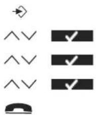
Ringer volume
You can choose from 5 handset ringer volume levels and off.

text_image
Diagram showing directional arrows, checkmarks, and a telephone handset symbol with standard icons1Enter the menu.
2Select "Handset" and confirm.
3Select "Ringer volume" and confirm.
The current setting is displayed.
4Press the up key to increase the volume.
5Press the down key to decrease the volume.
6Select "Save" to confirm.
7 Return to standby.
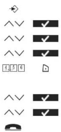
6.2 Handset name
You can change the name displayed on the handset during standby (max. 9 characters).

1Enter the menu.
2Select "Handset" and confirm.
text_image
^^V 4 5 6 ◀C ▶ 电话3Select "Handset name" and confirm.
4Enter the name you want.
5Press the soft menu key to correct.
6Select "Save" to confirm.
7Return to standby.
6.3 Keypad beeps
text_image
Icon set with checkmarks and directional arrows, likely representing a checklist or checklist system1Enter the menu.
2Select "Handset" and confirm.
3Select "Keypad beep" and confirm.
4Select "On" or "Off" and confirm.
5Return to standby.
6.4 Setting the contrast
text_image
Icon set with checkmarks and directional arrows, likely representing a checklist or checklist system1Enter the menu.
2Select "Handset" and confirm.
3Select "Contrast" and confirm.
4Select the contrast you want (1-8) and confirm.
5Return to standby.
6.5 Autotalk
When there is an incoming call and the handset is on the base, the phone automatically takes the line when lifted from the base. This function can be turned on or off.

text_image
Icon set with directional arrow, three checkmarks, and a telephone handset symbol1Enter the menu.
2Select "Handset" and confirm.
3Select "Autotalk" and confirm.
4Select "On" or "Off" and confirm.
5Return to standby.
6.6 Setting the display backlight Time
You can adapt the number of seconds the display backlight stays on after the last action.

text_image
Icon set with checkmarks and directional arrows, likely representing a checklist or checklist system1Enter the menu.
2Select "Handset" and confirm.
3Select "Backlight Time" and confirm.
4Select "10", "20", "30" or "40" sec. and confirm.
5Return to standby.
6.7 Prefix code
It is possible to use your telephone with a prefix number. When dialling telephone numbers, you can add automatically the prefix code before the number.
text_image
Cropped image showing a row of symbols and checkmarks, likely from a UI or system interface.1Enter the menu.
2Select "Handset" and confirm.
3Select "Prefix" and confirm.
4Select "Edit" and confirm.
5Enter the prefix code, e.g. '0' and select "Save".
OR
4Select "On/Off" and confirm.
5Select "On" or "Off" and confirm.
6Return to standby.
6.8 Using the alarm feature
You can have a different alarm setting for each handset registered to your base. The alarm rings only at the handset, not at the base or any other handset.
Set the alarm
text_image
Diagram showing various symbols and checkmarks, including arrow, checkmark, and arrowhead indicators with numbered boxes.1Enter the menu.
2Select "Alarm/Clock" and confirm.
3Select "Set alarm" and confirm.
4Select "Once", "On daily", "Mon to Fri" or "Off" and confirm.
If you have selected “Once”, “On daily” or “Mon to Fri”, the display will show:
Time (24Hr):
00:00
5Enter the time you want the telephone to ring and confirm with "Save".
6Select the desired ringtone and confirm with "Save".
7To deactivate the alarm, select "Off" and confirm.
8Return to the previous menu.
6.9 Setting the date and time
text_image
Diagram showing various directional and checkmark symbols with arrows and numbers, likely representing a UI or control panel.1Enter the menu.
2Select "Alarm/Clock" and confirm.
3Select "Date & Time" and confirm.
4Enter year, month, day, time and minutes and select "Save" to confirm.
5Return to the previous menu.
6.10 Setting the time format

1Enter the menu.
2Select "Alarm/Clock" and confirm.
3Select "Time format" and confirm.
4Select "12Hrs" or "24Hrs" and confirm.
5Return to the previous menu.
7 Base settings
7.1 Ringtone
You can choose from 9 different ringer melodies.
text_image
Icon set with checkmarks and a telephone handset, likely representing a checklist or navigation system.1Enter the menu.
2Select "Base Settings" and confirm.
3Select "Ringtone" and confirm.
4Select the desired melody and confirm.
During scrolling a sample is played.
5Return to standby.
7.2 Ringer Volume
You can choose from 5 base ringer volume levels.

text_image
Diagram showing directional and checkmark symbols with arrows and icons, likely representing a UI or navigation system.1Enter the menu.
2Select "Base Settings" and confirm.
3Select "Ringer Volume" and confirm.
The current setting is displayed.
4Press the up key to increase the volume.
5Press the down key to decrease the volume.
6Select "Save" to confirm.
7 Return to standby.
7.3 Dial Mode
There are 2 types of dialling mode:
• DTMF/Tone dialling (most common used)
- Pulse dialling (for older installations)
To change the dialling mode:
text_image
Icon set with directional arrows, checkmarks, and a telephone handset symbol1Enter the menu.
2Select "Base Settings" and confirm.
3Select "Dial mode" and confirm.
4Select "Tone" or "Pulse" and select "Save".
5Return to standby.
7.4 Recall (Flash)
Press the Flash key “R” (Key 4 - Picture 2C) to use certain services on your external line such as “call waiting” (if your phone company offers this feature); or to transfer calls if you use a
telephone exchange (PABX). The Flash key “R” is a brief interruption of the line. You can set the flash time to 100ms or 250ms.
text_image
Diagram showing various directional and checkmark symbols including arrow, double chevrons, checkmarks, and a telephone handset.1Enter the menu.
2Select "Base Settings" and confirm.
3Select "Recall" and confirm.
4Select short flash time (100ms) or long flash time (250ms) and select "Save".
5Return to standby.
7.5 System PIN
The System PIN is used for registering and deregistering handsets and some other optional settings. The default System PIN is 0000.
text_image
Diagram showing directional arrows, checkmarks, and phone icons with numbers 4,5,6 and a telephone handset1Enter the menu.
2Select "Base Settings" and confirm.
3Select "System PIN" and confirm.
4Enter the old PIN (0000 by default) and select "Save".
5Enter the new PIN, select "Save" and repeat this.
6Return to standby.
8 Tools
8.1 Appointment
You can set 5 appointments or reminders which you can give a name and an alarm by date and time.
text_image
Diagram showing various phone icons and symbols, including directional arrows, checkmarks, and standard icons.1Enter the menu.
2Select "Tools" and confirm.
3Select "Appointments" and confirm.
4Select one of the 5 appointments and select "Option".
To edit the appointment:
5Select "Edit" and confirm.
6Edit the name of the appointment and select "Save".
7 Enter the date of the appointment and select "Save".
8Enter the time and select "Save".
9Select the desired alarm melody and select "Save".
10Return to standby.
To delete the appointment:
5Select "Delete" and confirm.
6Press the right soft menu key to confirm.
7Press the left soft menu key to go back.
8Return to standby.
8.2 Stopwatch
flowchart
graph TD
    A["Start"] --> B{Check}
    B -->|Yes| C["Process Step"]
    B -->|No| D["End"]
1Enter the menu.
2Select "Tools" and confirm.
3Select "Stopwatch" and confirm.
4Select "Start" to start the stopwatch.
5Select "Stop" to stop the stopwatch.
Select "Start" again to restart.
Select "Reset" to reset the counter.
6Return to standby.
9 Additional handsets and base stations
You can subscribe up to 4 handsets on a base. Each handset can register up to 4 base stations and the user can select the base he wants to use.
9.1 Adding a new handset

Only needed when you have deregistered a handset or when you bought a new one.
To put the base into registration mode:

1Press and hold the paging key on the base.
The LED on the base will start to blink on the base for 90 seconds. During that time, the base is ready to register.
On the handset:
text_image
Diagram showing directional arrows and checkmarks on a grid of symbols including a phone icon1Enter the menu.
2Select "Handset" and confirm.
3Select "Registration" and confirm.
4Select "Register" and confirm.
5Select the number of the base to be associated with the handset (1-4) and confirm.
6Enter the system PIN (0000 by default) and confirm.
7Return to standby.
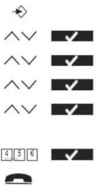
9.2 Removing a handset
This procedure needs to be carried out on a different handset then the one you want to remove.
text_image
Diagram showing directional arrows and checkmarks for phone call, with numbers 4, 5, 6 labeled below each.1Enter the menu.
2Select "Handset" and confirm.
3Select "Registration" and confirm.
4Select "De-Register" and confirm.
5Enter the system PIN (0000 by default) and confirm.
6Enter the handset number that needs to be removed and confirm.
7 Return to standby.
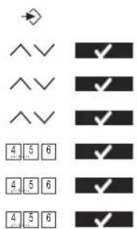
9.3 Select a base
You can switch your handset between bases. You can also set it to automatically base select with the strongest signal. The handset must first be registered with each base individually.

text_image
Diagram showing four rows of checkmarks and downward-pointing arrows, likely indicating selection or status indicators.1Enter the menu.
2Select "Handset" and confirm.
3Select "Select Base" and confirm.
4Select "Manual" or "Auto" and confirm.
If you have selected "Manual":
5Select the base to be associated with the handset and confirm.

When you have activated Automatic base selection and the handset is out of range on the current base, the handset will only search for the strongest base in standby (not during communication).
9.4 Using the intercom feature
Calling an internal handset
| INT | 1Press the left key INT.The screen displays “Handset _”. |
| 4 5 6 | 2Enter the internal number of the handset you want to call. |
| 3Press the on-hook key to hang up or put the handset back on the base. |
Transfer an external call to another handset
During an external call:
| INT | 1Press the left key INT.The screen displays “Handset _”. |
| 4 5 6 | 2Enter the internal number of the handset you want to call.Your external correspondent is placed on hold. |
| 3When the internal correspondent answers, press the on-hook key to transfer the call.OR | |
| INT | 3If the inthermal correspondent doesn’t answer, press the left key INT to retrieve the external correspondent or to go from one to the other. |
| 4Press the on-hook key to hang up or put the handset back on the base. |
Conference call
You can talk between 2 handsets and an external line at the same time.
During an external call:
| INT | 1Press the left key INT.The screen displays “Handset _”.2Enter the internal number of the handset you want to call.Your external correspondent is placed on hold. |
| ☐ | 3When the internal correspondent answers, select “Conf.”. OR |
| INT | 3If the internal correspondent doesn’t answer, press the left key INT to retrieve the external correspondent. |
| 4Press the on-hook key to hang up or put the handset back on the base. |
Taking an external call during an internal communication
When you are on intercom with another handset, you can still pick up outside calls.
To take an incoming call:

1Press the on-hook key. The internal communication is now interrupted. 2Press the off-hook key. You are now in communication with the outside caller.
10 Answering machine
The Butler 5750 has a built-in digital answering machine with a recording capacity of 11 min. The answering machine can be operated by the handset and remotely. It has the possibility of recording two outgoing messages (OGM 1 and OGM 2) (maximum of 2 min).
There are 2 possibilities:
- With OGM 1, the caller has the possibility to leave a message - With OGM 2, only the outgoing message is given without the caller having the opportunity to leave a message
The max. recording time for each incoming message = 3 min.
An internal voice will state various information, such as day and time of the call, as well as settings such as VIP code, ringer tones ... The language of the internal voice is stated on the packaging!

All messages playback is activated in speaker mode, to switch between earpiece and speaker you have press the off-hook -key
10.1 Display
The display on the handset will indicate how many messages you have received. If the answering machine is switched Off, the -Icon is shown. If it's turn On the will be shown.
‘Memory Full’ will be shown on the display when the internal memory is full and no new messages can be recorded.
When there are new messages on your answering machine the LCD backlit will blink to indicate this.
10.2 Outgoing Messages
Two outgoing messages of 2 minutes can be recorded (OGM1 and OGM2).
- Outgoing message 1 for the answering function and possibility for callers to leave a message.
- Outgoing message 2 for the answering function without allowing callers to leave a messages on the machine.
Recording outgoing message (OGM 1 or OGM 2)

1Enter the menu.

text_image
Image showing a row of checkmark symbols and a bottom-right icon, likely indicating selection or confirmation.2Select "Ans Machine" and confirm.
3Select "Outgoing Msg" and confirm.
4Select "Record Message" and confirm.
5Select 'Answer & Record' for OGM1 or 'Answer Only' for OGM2.
6Start speaking after the beep and press 'Save' to confirm. The recorded message will be played back.
7 During playback press 'Delete' to erase or press 'Stop' to interrupt the playback.

The recording cannot exceed 2 minutes. If no outgoing message is recorded, the prerecorded outgoing message is used.
Playback the Outgoing Message
To check the outgoing message:

text_image
Diagram showing five identical arrow symbols pointing to a diamond shape, each paired with a checkmark and a downward arrow.1Enter the menu.
2Select "Ans Machine" and confirm.
3Select "Outgoing Msg" and confirm.
4Select "Play Message" and confirm.
5Select ‘Answer & Record’ for OGM1 or ‘Answer Only’ for OGM2 and confirm.
6The message will be played back. Press 'Delete' to erase or press 'Stop' to interrupt the playback.
Select outgoing message (Answering mode)

text_image
Image showing a sequence of checkmark symbols and checkmarks, likely indicating selection or confirmation steps.1Enter the menu.
2Select "Ans Machine" and confirm.
3Select "Ans Settings" and confirm.
4Select "Answer Mode" and confirm.
5Select ‘Answer & Record’ for OGM1 or ‘Answer Only’ for OGM2 and confirm.
Erasing the Outgoing Message
If you erase the outgoing message, the default message will be played.
During playback of the outgoing message (see above) you can delete the message by pressing 'Delete'.
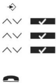
10.3 Turning Answering Machine On/Off
If the answering machine is switched Off, the -icon is shown. If it's turn On the -icon will be shown and the machine will automatically pick up the line after a number of rings (see "10.4 Setting number of Rings (Answer delay)").

1Enter the menu.
2Select "Ans Machine" and confirm.
3Select "Ans On/Off" and confirm.
4Select 'On' or 'Off'.

Even if the answering machine is off, the machine will automatically pick up after 10 rings in order to enable remote activation (see “10.13 Turning answering machine on remotely”).
10.4 Setting number of Rings (Answer delay)
The number of rings after which the answering machine will answer calls can be set from 2 – 9 and TS (Toll saver). The standard setting is 5 rings. In Toll saver mode, the machine will answer after 5 rings if there are no new messages, and after 2 rings if there are new messages. If there are no new messages and you call your machine to check your messages remotely (see “10.12 Remote Operation”), you can hang up after the 2nd ring. You do not need to pay connection fees and you know that you don’t have any new messages.

text_image
Image showing a sequence of checkmark symbols and checkmarks, likely representing selection or confirmation steps.1Enter the menu.
2Select "Ans Machine" and confirm.
3Select "Ans Settings" and confirm.
4Select "Answer Delay" and confirm.
5Select 2-9 or 'Toll Saver' and confirm.
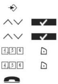
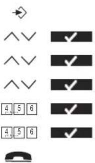
10.5 Programming the VIP Code
The VIP code is a 3-digit code used to operate the machine remotely (see “10.12 Remote Operation”). The VIP code is set to '321' by default.
Changing the VIP code
text_image
Diagram showing directional arrows and checkmarks with numerical labels below each bar, likely representing a logic or control mechanism.1Enter the menu.
2Select "Ans Machine" and confirm.
3Select "Ans Settings" and confirm.
4Select "Security Code" and confirm.
5Enter the old PIN (321) and confirm.
6Enter the new PIN and confirm.
7Enter the new PIN again and confirm.
10.6 Operation
If a call is received and the answering machine is turned on, the answering machine will automatically pick up the line after the set number of rings. If
- Outgoing message 1 has been selected, it will be played. After the outgoing message, a beep will be heard and the caller can leave a message (of a max. 3 minutes).
- Outgoing message 2 has been selected, it will be played. After the beep, the line will automatically be disconnected. The caller does not have the possibility to leave a message.

If, during recording, nothing is said for 8 seconds, the line will be automatically disconnected.
10.7 Call Screening
During the outgoing message playback or incoming message recording, you can hear to other side of the line by pressing the Off-hook key. The display will show 'Call Screening' and you can press the right-soft key to stop the answering machine and to talk to the caller.

If you have a second handset registered on the same base of your Butler 5750, you can stop the answering machine by pressing the ‘#’-key during call screening.
10.8 Recording a Memo
With the Butler 5750, you can record memos. These memos are considered an incoming message that can be picked up later by the user. The max. recording time for a memo is 3 minutes.
1Enter the menu.
2Select "Ans Machine" and confirm.
3Select "Record Memo" and confirm.
4Start speaking after the beep and select 'Save' to end the recording.
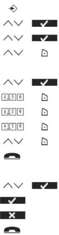
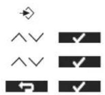
10.9 Playback of Incoming Messages and Memos
When there are new messages you can playback all new message by the soft-key:

1Press the right soft-menu key.
Or by the Menu:
text_image
Diagram showing directional arrows and checkmarks with three identical rectangular blocks, likely representing a checklist or selection system.1Enter the menu.
2Select "Ans Machine" and confirm.
3Select "Play Msgs" and confirm.
4 Select "Play New Msgs" for the new only, or "Play All Msgs" for old and new messages playback.
During Playback you can:
Delete the message if you select 'Delete'


Go to the next message when you select 'Next' or press the skip forward button

Go back to the beginning of the current message press the skip backwards key ones, to jump back to the previous message press the backwards key twice.

Pause the message playback by pressing the pause key. Press the pause key again to continue.

Stop the playback by pressing the Stop-key
10.10 Erasing Messages
During playback of the messages you can erase the message one by one as above described. You can also erase all played messages:
1Enter the menu.
2Select "Ans Machine" and confirm.
3Select "Delete Msgs" and confirm.
4 Confirm again or select back to stop.
10.11 Memory Full
If the memory is full, “MEMORY FULL” will appear on the display. If the answering machine is turned on and a call comes in, the machine will automatically play OGM 2 (answering machine function without recorded caller message).
When listening to the messages, the internal voice will say that the memory is full and then play back the messages.
Erase the messages one by one during listening or all by the menu as above described.
10.12 Remote Operation

The answering machine can only be operated remotely using a tough-tone phone (DTMF tone selection system).
4 5 6
1Call your machine.
The answering machine picks up the line, you hear the outgoing message and a beep.
4 5 6
2Slowly dial the VIP code (default 321)
You will hear two short beeps for confirmation.
4 5 6
3Enter the next codes to use the desired function:
Listening to Messages
2
4Press '2' to Listen to messages
The answering machine will play the messages.
During playback, you have the following options:
2
5Press '2' to Pause playback
6Press '2' to Restart playback.
2
3
①
5Press '3' to go to the Next Message.
5Press '1' '1' to go to the Previous Message.
1
5Press '1' to Repeat the current message.
1
5Press '6' to stop playback.
6
5Press '7' to erase the current message.
7
Erasing All Old Messages
(0)
6 After listening to all messages, press '0' to erase all messages.
Playing Outgoing Message
4
4Press '4' to play the current outgoing message.
Recording Outgoing Message
9
4Press '9' to select OGM 1 or OGM 2.
5
5Press '5' to start recording.
A beep will indicate that you can start recording.
6
6Say your message.
7Press '6' to stop recording.

The recording will be ended automatically after 2 minutes.
Turning Answering Machine On/Off
9
4Press '9' to switch on the answering machine.
9
5Press '9' to switch between OGM1 and OGM2
8
6Press the '8' key to turn off the answering machine.
Ending Remote Operation
6
Press '6' to end remote operation.
10.13 Turning answering machine on remotely
If the answering machine is switched off, you can turn it on remotely:
4 5 6
1Call your machine.
The machine will pick up automatically after 10 rings and play outgoing message 2.
4 5 6
2Dial the VIP code (default 321) slowly while the message plays.
9
3Press '9' to switch on the answering machine.
The internal voice will say that the answering machine has been turned on.
6
4Press '6' to end remote operation.
11 Troubleshooting
| Symptom Possible cause Solution | ||
| No display Batteries uncharged | Check the position of the | batteries |
| Recharge the batteries | ||
| Handset turned OFF Turn ON the | handset | |
| No tone Telephone cord badly | connected Check the telephone cord connection | |
| The line is occupied by another handset | Wait until the other handset hangs up | |
| The icon flashes | Handset out of range Bring the handset closer to the base | |
| The base has no power supply Check the mains connection to the base | ||
| The handset is not registered on the base | Register the handset on the base | |
| Base or handset do not ring The ringing volume is off or low Adjusted the ringing volume | ||
| Not possible to transfer a call on PABX | The Flash Time is too short or too long | Change the Flash Time |
| Telephone does not react to pressing the keys | Manipulation error | Remove the batteries and put them back in place |
12 Technical data Technical characteristics
Standard DECT(Digital Enhanced Cordless Telecommunications) GAP (Generic Access Profile)
Frequency range 1880 MHz to 1900 MHz
Number of channels 120 duplex channels
Modulation GFSK
Speech coding 32 kbit/s
Emission power 10 mW (average power per channel)
Range 300m in open space /50m maximum inhouse
Number of handsets Up to 4
Base powersupply 230V / 50 Hz / 6V DC 300mA
Handset Batteries: 2 rechargeable batteries AAA, NiMh 1,2V, 600mA
Handset autonomy 110 hours in standby
Handset talk time 11 hours
Normal conditions of use +5 °C to +45 °C
Dialling mode Pulse / Tone
Flash time 100 or 250 ms
13 Warranty
13.1 Warranty period
The Topcom units have a 24-month warranty period. The warranty period starts on the day the new unit is purchased. The warranty on batteries is limited to 6 months after purchase. Consumables or defects causing a negligible effect on operation or value of the equipment are not covered.
The warranty has to be proven by presentation of the original purchase receipt, on which the date of purchase and the unit-model are indicated.
13.2 Warranty handling
A faulty unit needs to be returned to a Topcom service centre including a valid purchase note.
If the unit develops a fault during the warranty period, Topcom or its officially appointed service centre will repair any defects caused by material or manufacturing faults free of charge.
Topcom will at its discretion fulfil its warranty obligations by either repairing or exchanging the faulty units or parts of the faulty units. In case of replacement, colour and model can be different from the original purchased unit.
The initial purchase date shall determine the start of the warranty period. The warranty period is not extended if the unit is exchanged or repaired by Topcom or its appointed service centres.
13.3 Warranty exclusions
Damage or defects caused by incorrect treatment or operation and damage resulting from use of non-original parts or accessories not recommended by Topcom are not covered by the warranty.
Topcom cordless phones are designed to work with rechargeable batteries only. The damage caused by the use of non-rechargeable batteries is not covered under warranty.
The warranty does not cover damage caused by outside factors, such as lightning, water and fire, nor any damage caused during transportation.
No warranty can be claimed if the serial number on the units has been changed, removed or rendered illegible.
Any warranty claims will be invalid if the unit has been repaired, altered or modified by the buyer or by unqualified, non-officially appointed Topcom service centres.
14 Disposal of the device (environment)

At the end of the product lifecycle, you should not throw this product into the normal household garbage but bring the product to a collection point for the recycling of electrical and electronic equipments. The symbol on the product, user guide and/or box indicate this.
Some of the product materials can be re-used if you bring them to a recycling point.
By re-using some parts or raw materials from used products you make an important contribution to the protection of the environment.
Please contact your local authorities in case you need more information on the collection points in your area.
15 Cleaning
Clean the telephone with a slightly damp cloth or with an anti-static cloth. Never use cleaning agents or abrasive solvents.
16 ECO (low-radiation) mode
- This cordless telephone (compliant with the DECT standard) facilitates low-radiation operation.
- The radiation intensity of the radio signal between the base station and handset is reduced to a minimum when the handset is on the base station.
- Only when the handset is removed from the base station or a call is received does the radiation intensity of the radio signal increase to the normal strength.
- This does not mean that normal DECT radiation is harmful to health.
- The low-radiation mode prevents unnecessary DECT radiation load when no communication is required between the base station and handset.
- For technical reasons, no additional handsets can be operated in low-radiation mode (an additional handset that is not located in the immediate vicinity of the base station would always be "searching for base station" due to the weak radio signal).
- Low-radiation mode is enabled in the factory settings.
- Low-radiation mode is automatically disabled if you log on an additional handset.
- Low-radiation mode is automatically enabled again when you log off all additional handsets (only one handset may be logged onto the base station).
- The procedure for logging handsets on and off is explained in the User Manual.
Nederlands
text_image
Electrical wiring diagram showing connections between a router, switches, and power outlet with labeled components A and Btext_image
Scanned image showing a row of icons and checkmarks, likely representing UI or security symbols.text_image
User interface icons including directional arrows, checkmarks, and phone calltext_image
Icon set with checkmarks and directional arrows, likely representing a checklist or checklist systemtext_image
Icon set with checkmarks and directional arrows, likely representing a checklist or checklist systemtext_image
Icon set with checkmarks and directional arrows, likely representing a checklist or checklist systemtext_image
Icon set with checkmarks and directional arrows, likely representing a checklist or checklist systemtext_image
Diagram showing various symbols and checkmarks, including directional arrows, checkmarks, and numbers 4, 5, 6, and a telephone.text_image
Diagram showing various directional symbols and checkmark indicators with arrows pointing to specific shapes.text_image
Diagram showing various directional and checkmark symbols with numerical labels 4, 5, 6 and an arrow pointing to a left-pointing arrow.text_image
Diagram showing directional arrows and checkmarks on four horizontal bars, likely representing a flow or selection system.text_image
Icon set with checkmarks and directional arrows, likely representing a checklist or checklist systemtext_image
Diagram showing directional and checkmark symbols with arrows and checkmarks, likely representing UI or system control icons.text_image
Diagram showing various directional and symbolic icons including arrows, chevrons, checkmarks, and a phone.text_image
Icon set with directional arrows, checkmarks, and a telephone handset symboltext_image
Cropped image showing various phone function icons including directional arrows, checkmarks, and numbers 4, 5, 6.text_image
Diagram showing various arrow symbols and checkmark indicators, likely representing a UI or control panel.text_image
Diagram showing various directional and checkmark symbols with corresponding icons, likely representing a UI or system interface.text_image
Diagram showing directional arrows and checkmarks over a keypad with numbers 4, 5, 6text_image
Diagram showing five rows of checkmarks and an arrow pointing to the top-left square, likely indicating selection or confirmation steps.text_image
Diagram showing a sequence of checkmarks and numbers, likely representing a logic or data flow setup.text_image
Electrical wiring diagram showing connections between a router, switches, and power outlet with labeled components A and Bb :B.Batteries rechargeables

text_image
Collection of basic phone icons including alarm, phone, and keyboard symbolstext_image
Scanned image showing a vertical list of symbols and checkmarks, likely representing user interface or checklist items.text_image
Diagram showing directional and checkmark symbols with arrows and icons, likely representing UI or navigation functions.text_image
User interface icons including directional arrows, checkmarks, and phone calltext_image
Icon set with checkmarks and arrow symbols, likely representing a checklist or checklist systemtext_image
Electrical circuit symbols including a switch, three identical switches, and a telephone handsettext_image
Icon set with checkmarks and directional arrows, likely representing a checklist or checklist systemtext_image
Icon set with checkmarks and directional arrows, likely representing a checklist or checklist systemtext_image
Cropped image showing a row of symbols and checkmarks, likely representing basic UI or security icons.text_image
Diagram showing various directional and checkmark symbols with arrows and numbers, likely representing a UI or control panel.text_image
Diagram showing directional arrows and checkmarks with three identical rectangular blocks, one with an arrow pointing to the top-left corner.text_image
Icon set with directional arrow, checkmarks, and a telephone handset symboltext_image
Image showing a vertical list of directional and symbolic icons, including up/down arrows, down arrow, checkmark, and telephone.text_image
Collection of directional and checkmark icons including arrows, chevron, and document symbolstext_image
Diagram showing directional arrows, checkmarks, and a telephone handset symbol with standard layouttext_image
User interface icons including directional arrows, checkmarks, and phone number 4.5.6text_image
Diagram showing directional arrows and checkmarks on a grid of symbols, including numbers 4, 5, 6 and a telephone icon.text_image
Diagram showing directional arrows and checkmarks on a grid of symbols, including numbers 4, 5, 6 and a telephone icon.text_image
Diagram showing four rows of checkmarks and two rows of inverted chevrons, likely indicating selection or confirmation steps.text_image
Diagram showing a sequence of checkmark symbols and an arrow pointing to it, likely indicating a process or selection.text_image
Diagram showing five identical checkmark symbols with arrowheads, likely representing a checklist or selection system.text_image
Diagram showing five rows of checkmarks and two rows of inverted chevrons, with an arrow pointing to the top row.text_image
Diagram showing five rows of checkmarks and an arrow symbol, likely representing a checklist or selection system.text_image
Diagram showing a sequence of checkmarks and numbers, likely representing a logic or operation flow.text_image
Electrical wiring diagram showing connections between a device, switches, and power outlet with labeled components A, B, and C.text_image
Scanned image showing a vertical list of symbols and checkmarks, likely representing user interface or checklist items.text_image
Diagram showing directional and checkmark symbols with arrows, including a phone icontext_image
User interface icons including directional arrows, checkmarks, and phone call with numeric input fieldstext_image
Icon set with checkmarks and a phone symbol, likely representing a checklist or status indicator.text_image
Electrical signal icons including a diamond, three identical checkmarks, and a telephone handset symboltext_image
Icon set with directional arrow, checkmarks, and phone symbol in vertical layouttext_image
Icon set with checkmarks and a phone symbol, likely representing a checklist or status indicator.text_image
Diagram showing various directional and checkmark symbols with corresponding icons, likely representing a UI or system interface.text_image
Diagram showing various directional and checkmark symbols with numbered boxes and arrows, likely representing a UI or control panel.text_image
Icon set with checkmarks and a telephone handset, likely representing a basic phone or call interface.text_image
Diagram showing directional and checkmark symbols with arrows and icons, likely representing a UI or call interface.text_image
Icon set with directional arrows, checkmarks, and a telephone handset symboltext_image
Icon set with directional arrows, checkmarks, and a telephone handset symboltext_image
Diagram showing directional arrows and checkmarks, likely representing a navigation or system interface with symbols like '✓' and geometric shapes.text_image
Diagram showing directional arrows and checkmarks with corresponding numerical values below each bar, including a telephone icon.text_image
Diagram showing directional arrows and checkmarks on a keypad layout with numbers 4,5,6 and a telephone icon.text_image
Diagram showing a sequence of checkmark symbols and an arrow pointing to the top-left box, likely indicating selection or confirmation steps.text_image
Diagram showing checkmark symbols and arrow pointing to a diamond shape, with four rows of checkmarks and two rows of inverted chevrons.text_image
Diagram showing checkmark symbols and checkmarks arranged in vertical columns, with an arrow pointing to the top-left corner.DECT(Digital Enhanced Cordless Telecommunications)
GAP (Generic Access Profile)
text_image
Electrical wiring diagram showing connections between a router, switches, and power outlet with labeled components A, B, and C.text_image
Scanned image showing a row of icons and checkmarks, likely representing UI or security symbols.text_image
User interface icons including directional arrows, checkmarks, and phone calltext_image
Icon set with checkmarks and directional arrows, likely representing a checklist or checklist systemtext_image
Icon set with checkmarks and directional arrows, likely representing a checklist or checklist systemtext_image
Icon set with checkmarks and a phone, likely representing a checklist or status indicator.text_image
Electrical control symbols and function keys arranged in rows, including directional arrows, checkmarks, and phone icons1 Acceda al menú.
text_image
Icon set with checkmarks and a telephone handset, likely representing a basic phone or call interface.text_image
Diagram showing directional and checkmark symbols with arrows and checkmarks, likely representing a UI or checklist interface.text_image
Diagram showing directional and checkmark symbols with arrows and a telephone handset icontext_image
Cropped image showing a row of basic phone icons and symbols, including checkmarks, numbers 4, 5, 6, and a telephone.text_image
Diagram showing various symbols and checkmark indicators with arrow and checkmark shapestext_image
Image showing a set of five black-and-white icons representing phone, signal, checkmark, cross, and telephone symbols.text_image
Diagram showing directional arrows and checkmarks with corresponding symbols, likely representing a navigation or checklist system.1Acceda al menú.
text_image
Diagram showing directional arrows and checkmarks on a grid of symbols, including numbers 4, 5, 6 and a telephone icon.1 Acceda al menú.
text_image
Diagram showing various arrow symbols and checkmark indicators, likely representing directional or symbolic data.text_image
Diagram showing five identical checkmark symbols with arrow indicators, likely representing a checklist or selection system.text_image
Diagram showing a sequence of checkmark symbols and an arrow pointing to the top-left box, likely indicating selection or confirmation steps.text_image
Diagram showing checkmark symbols and arrow pointing to a diamond shape, with five identical checkmarks arranged in two rows.text_image
Diagram showing a sequence of checkmarks and numbers, likely representing a checklist or selection system.text_image
Electrical wiring diagram showing connections between a router, switches, and power outlet with labeled components A and B- 2A Πίσω όψη βάσης -
text_image
Diagram with geometric shapes and numbered labels, including a checkmark and directional arrowsnatural_image
Pure electrical circuit lines without any symbolstext_image
Scanned image showing a vertical list of symbols and checkmarks, likely representing user interface or checklist items.text_image
Scanned image showing a row of basic icons and checkmarks, likely representing UI or security symbols.text_image
Diagram showing directional arrows and checkmarks on a vertical bar layout, with a telephone icon below.text_image
Diagram showing directional and checkmark symbols with arrows and text labelstext_image
User interface icons including directional arrows, checkmarks, and phone calltext_image
Electrical circuit symbols and checkmark indicators for various switch configurationstext_image
Icon set with directional arrow, three checkmarks, and a telephone handset symboltext_image
Icon set with directional arrows, checkmarks, and a telephone handset symboltext_image
Diagram showing various geometric shapes and checkmark indicators, including arrow, chevron, and four numbered boxes.text_image
Diagram showing various directional and checkmark symbols with arrows and numbers, likely from a software interface or design tool.text_image
Diagram showing directional arrows and checkmarks with checkmarks, likely representing a flow or selection process.text_image
Icon set with checkmarks and a telephone handset, likely representing a checklist or checklist.text_image
Diagram showing directional arrows, checkmarks, and document symbols with corresponding iconstext_image
Collection of directional and symbolic icons including arrows, checkmarks, and a phonetext_image
Icon set with directional arrows, checkmarks, and a telephone handset symboltext_image
Cropped image showing a row of symbols and icons, including arrows, checkmarks, numbers 4, 5, 6, and a telephone handset.text_image
Diagram showing various phone icons and symbols, including checkmarks, numbers, and directional arrowstext_image
Diagram showing directional arrows and checkmarks with checkmarks, likely from a UI or design tool interfacetext_image
Diagram showing directional arrows and checkmarks on various symbols and numbers, including a telephone icon.text_image
Diagram showing directional arrows and checkmarks aligned with four rows of rectangular blocks, labeled 4, 5, 6 below.text_image
Diagram showing four rows of checkmarks and downward-pointing arrows, likely indicating selection or status indicators.The image is too blurry to recognize any text content.
The image is too blurry to recognize any text content.
text_image
Image showing a sequence of checkmark symbols and an arrow pointing to the top-left corner.text_image
Diagram showing five rows of checkmarks and an arrow symbol, likely representing a checklist or selection system.text_image
Diagram showing a sequence of checkmark symbols and arrow indicators above vertical bars, likely representing a checklist or selection system.text_image
Diagram showing various arrow symbols and checkmarks, likely representing a logic or control mechanism with labeled rows and columns.RETURN WITH YOUR DEFECT PRODUCT
natural_image
Two identical vertical lines with evenly spaced tick marks, no text or symbols presentLocation/Ort./Lieu/Plaats: Post code/Postleitzahl/Code Postal/Postcode:

natural_image
Two identical rectangular grids with evenly spaced vertical lines, no text or symbols present.| Country/Land/Pays/Land: |
| Tel./Tél.: |
| E-mail: |
(Original Proof of Purchase has to be attached to this return card to be valid for warranty)