
Crystal 570X RGB - Desktop Computer CORSAIR - Free user manual and instructions
Find the device manual for free Crystal 570X RGB CORSAIR in PDF.
| Product type | ATX Mid Tower Case |
| Brand | Corsair |
| Model | Crystal 570X RGB |
| Material | Tempered glass and steel |
| Dimensions (L × l × H) | 480 mm × 234 mm × 512 mm |
| Compatible motherboard format | ATX, Micro-ATX, Mini-ITX |
| 3.5" hard drive bays | 2 |
| 2.5" SSD bays | 2 (also compatible with 3.5" drives) |
| Included fans | 3 × SP120 RGB (front) |
| Additional fan slots | Front: 3 × 120 mm / 2 × 140 mm; Top: 2 × 120/140 mm; Rear: 1 × 120 mm |
| Radiator compatibility | Front: 280/360 mm; Top: 240 mm; Rear: 120 mm |
| Max graphics card length | 370 mm |
| Max CPU cooler height | 170 mm |
| Max power supply length | 225 mm |
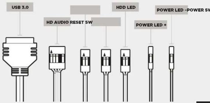
| Front panel connectors | USB 3.0, HD Audio, power button, reset, HDD LED, power LED |
| Dust filters | Yes (front, top, bottom) |
| Tempered glass panels | Side, front, top |
| Power supply cover | Yes, with PSU compartment |
| Integrated RGB controller | Yes, on the 570X RGB model |
| Color | Black (standard) |
Frequently Asked Questions - Crystal 570X RGB CORSAIR
User questions about Crystal 570X RGB CORSAIR
0 question about this device. Answer the ones you know or ask your own.
Ask a new question about this device
Download the instructions for your Desktop Computer in PDF format for free! Find your manual Crystal 570X RGB - CORSAIR and take your electronic device back in hand. On this page are published all the documents necessary for the use of your device. Crystal 570X RGB by CORSAIR.
USER MANUAL Crystal 570X RGB CORSAIR
© 2016 Corsair Components, Inc.
All rights reserved. Corsair, the sails logo, and Carolde Series are registered trademarks of Corsair in the United States and/or other countries. All other trademarks are the property of their respective owners. Product may vary slightly from those pictured.
PN: 49-001511 rev AA


CORSAIR
natural_image
Technical line drawing of a computer tower case showing internal components and ventilation slots (no text or labels)CRYSTAL SERIES
570X
INSTALLATION GUIDE ■ GUIDE D'INSTALLATION
INSTALLATIONSANLEITUNG ■ Guía de Instalación
РУКОВОДСТВО ПО УСТАНОВКЕ ■ GUIA DE INSTALAÇÃO
インストールガイド
English: 5-14
Français: 15-24
Deutsch: 25-34
Español: 35-44
Россию: 45-54
Português: 55-64
日本語: 65-74

CRYSTAL SERIES 570X
Table of Contents Case Specifications
| Congratulations: | 5 |
| Case specifications: | 6 |
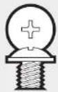
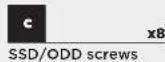
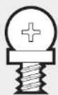
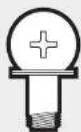
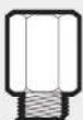
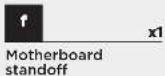
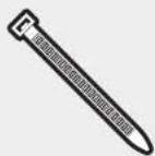
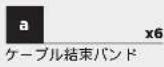
| Accessory kit contents: | 7 |
| Case features: | 8 |
| Removing the Side Panels: | 9 |
| Installing the Motherboard: | 9 |
| Installing HDDs: | 10 |
| Installing SSDs: | 10 |
| Installing the Power Supply: | 11 |
| Installing PCI-E/PCI Card(s): | 11 |
| Removing the Front and Top Panels: | 12 |
| Installing the Front I/O Connectors: | 12 |
| Removing Fan Trays: | 13 |
| Using RGB Fan Controller (570X RGB): | 13 |
| Frequently Asked Questions: | 14 |
Congratulations!
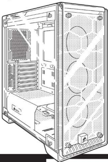
Thank you for purchasing the Crystal Series 570X - Tempered Glass, Premium ATX Mid-Tower Case.
Crystal Series 570X
With immaculate tempered glass enclosing the entire chassis, every component of your build is on display for all to see. The Crystal Series 570X provides enough space for virtually any size radiator and up to 6 case fans. With the 3 included SP120 fans and cable management made effortless, you can take personalization to the next level.
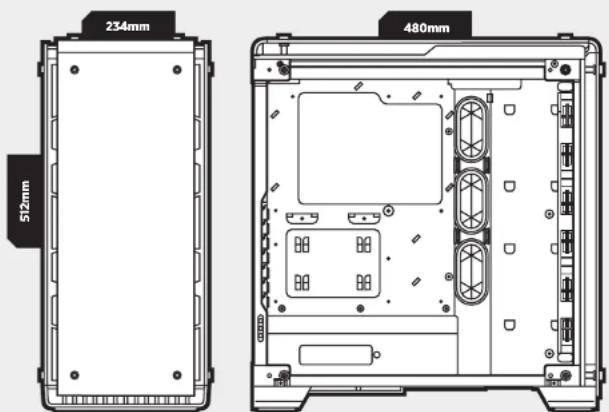
| Length: | 480mm |
| Width: | 234mm |
| Height: | 512mm |
| Maximum GPU length: | 370mm |
| Maximum CPU cooler height: | 170mm |
| Maximum PSU length: | 225mm |
| Fan locations: | |
| Front: | 3 x 120/2 x 140mm |
| Top: | 2 x 120/140mm |
| Rear: | 120mm |
| Radiator compatibility: | |
| Front: | 280mm/360mm |
| Top: | 240mm |
| Rear: | 120mm |

CRYSTAL SERIES 570X
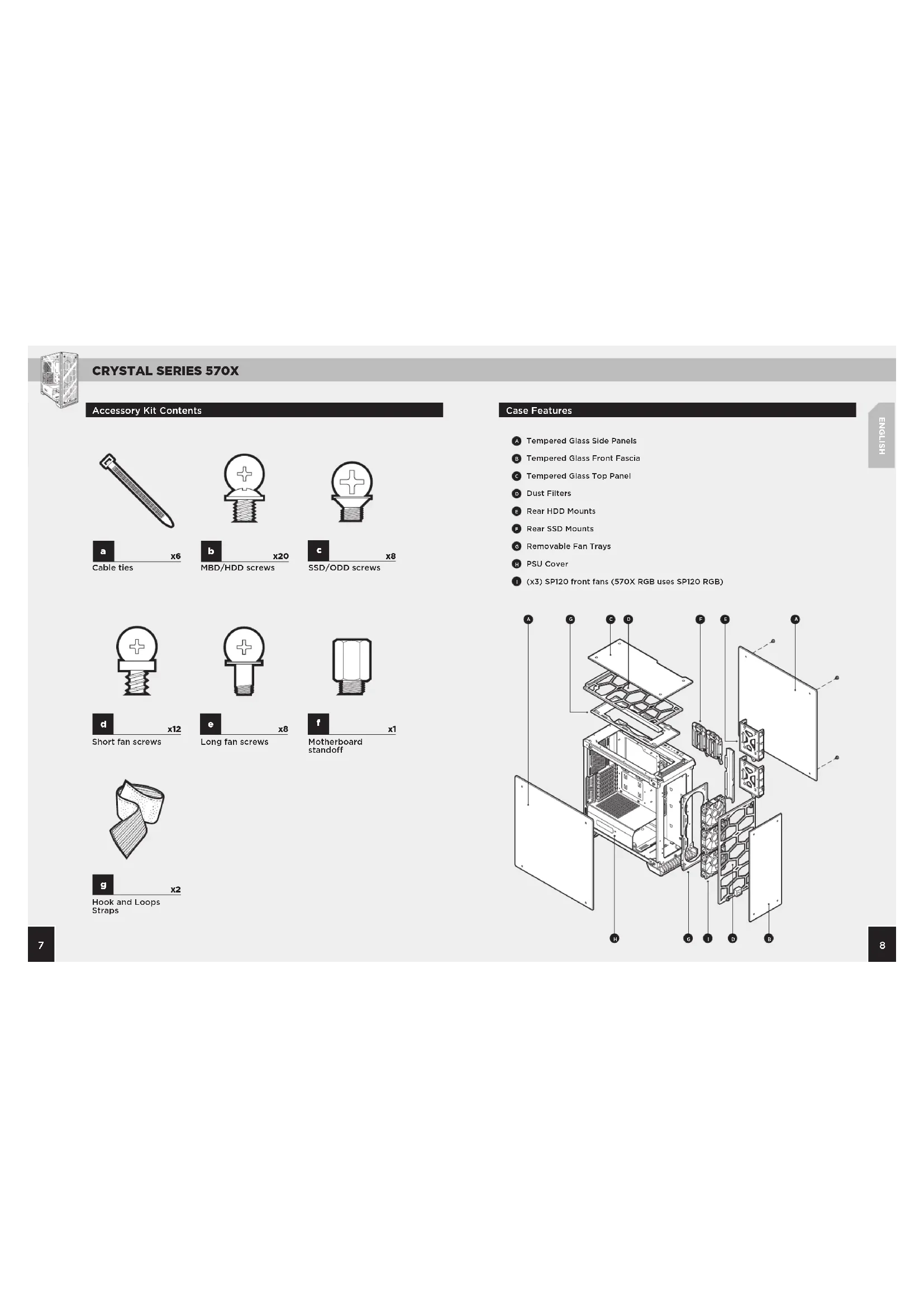
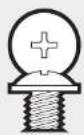
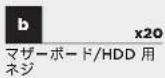
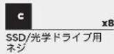
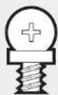
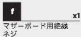
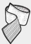
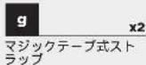
Accessory Kit Contents


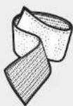

Case Features
Tempered Glass Side Panels
B Tempered Glass Front Fascia
Tempered Glass Top Panel
Dust Filters
E Rear HDD Mounts
F Rear SSD Mounts
Removable Fan Trays
H PSU Cover
(1) (x3) SP120 front fans (570X RGB uses SP120 RGB)

CRYSTAL SERIES 570X
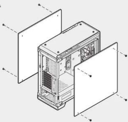
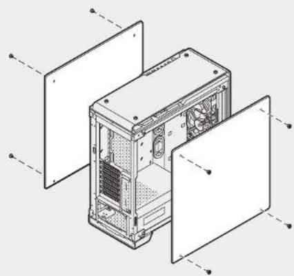
1. Removing the Side Panels
Remove the thumbs screws and pull the side panel off.
natural_image
Technical line drawing of a computer tower case with open doors and internal compartments (no text or symbols)2. Installing the Motherboard
Snap your motherboard's I/O shield into the cutout.
Align the motherboard with the standoffs in the case.
Secure with the included screws.
natural_image
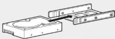
Technical line drawing of an internal computer chassis showing internal components and mounting points (no text or labels)3. Installing HDDs
Step 1 - Place the drive into the 3.5" drive tray.
Step 2 - Slide the drive and rail assembly into the HDD mounting location behind the motherboard as shown.
natural_image
Technical line drawing of a mechanical assembly with two components and a central housing (no text or symbols)Step 1
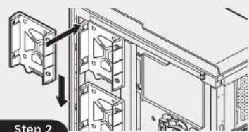
4. Installing SSDs
- Remove the screws to release the drive tray from the back of the motherboard tray.
- Slide the 2.5" drive into the tray until it snaps into place.
- Reattach the drive tray to the back of the motherboard tray.


CRYSTAL SERIES 570X
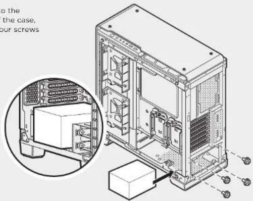
5. Installing the Power Supply
Install the PSU into the lower chamber of the case, and secure with four screws from behind.
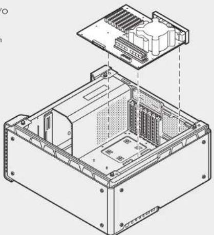
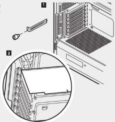
6. Installing PCI-E/PCI Card(s)
- Remove thumbscrews and corresponding slot covers.
- Install the expansion card and secure with thumbscrews.
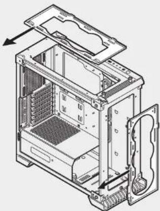
7. Removing the Front and Top Panels
Remove the thumb screws and pull off the glass panel.

- Installing the Front I/O Connectors
See your motherboard's manual for front panel header locations and pin-outs.

CRYSTAL SERIES 570X
Unscrew fan tray and slide out from chassis to install fans and radiators outside of chassis.
natural_image
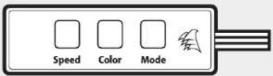
Technical line drawing of an internal computer case with visible cooling fans and ventilation slots (no text or labels)10. Using RGB Fan Controller (570X - RGB)
See Included RGB Fan controller Quick Start Guide for detailed instructions.
Frequently Asked Questions9. Removing Fan Trays
- Does the polarity matter with the I/O panel's power and reset header? No, only the LED headers.
- Who should I contact if I received my case damaged or one of the fans is no longer working? Please go to corsair.force.com and request an RMA so that we can replace the damaged part(s).
- Where can I mount a fan?
| Fan Mount Locations | |
| Front 3x120mm, 2x140mm (3x120mm included) | |
| Top 2x140mm/120mm | |
| Rear 120mm (included) | |
| Bottom x | |
| Side x | |
| Mid x | |
To learn more about this case visit the product page at corsair.com
CRYSTAL SERIES 570X

CRYSTAL SERIES 570X
CRYSTAL SERIES 570X
natural_image
Isometric line drawing of a computer tower case with visible internal components and external panel dividers (no text or labels)natural_image
Technical line drawing of an internal computer chassis showing internal components and mounting hardware (no text or labels)natural_image
Technical line drawing of a mechanical assembly with two components and a central housing (no text or symbols)Step 1

CRYSTAL SERIES 570X
natural_image
Technical line drawing of an internal computer case with visible internal components and mounting bracket (no text or labels)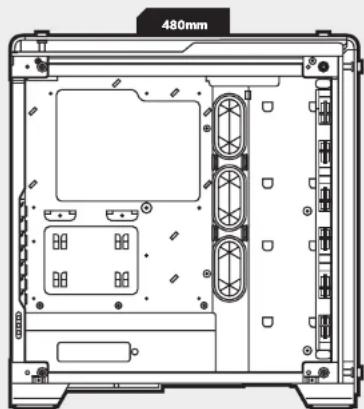
natural_image
Technical line drawing of a computer case with ventilation ducts and mounting hardware (no text or symbols)
CRYSTAL SERIES 570X

CRYSTAL SERIES 570X
natural_image
Isometric line drawing of a computer tower case with open doors and internal components (no text or symbols)2. Installation des Motherboards
natural_image
Technical line drawing of an internal computer chassis showing internal components and mounting points (no text or labels)natural_image
Technical line drawing of a mechanical assembly with two components and a central housing (no text or symbols)Step 1

CRYSTAL SERIES 570X
natural_image
Technical line drawing of an internal computer case with visible internal components and mounting brackets (no text or labels)
CRYSTAL SERIES 570X

CRYSTAL SERIES 570X
natural_image
Isometric line drawing of a computer tower case with open doors, showing internal components and mounting brackets (no text or symbols)2. Cómo instalar la placa base
natural_image
Technical line drawing of an internal computer chassis showing internal components and mounting points (no text or labels)natural_image
Technical line drawing of a mechanical assembly with two components and a central housing (no text or symbols)Step 1

CRYSTAL SERIES 570X
natural_image
Technical line drawing of an internal computer case with visible cooling fans and ventilation slots (no text or labels)
CRYSTAL SERIES 570X

CRYSTAL SERIES 570X
natural_image
Technical line drawing of a computer tower case with open doors and internal compartments (no text or symbols)natural_image
Technical line drawing of an internal computer chassis showing internal components and mounting points (no text or labels)natural_image
Technical line drawing of a mechanical assembly with two components and a central housing (no text or symbols)Step 1

CRYSTAL SERIES 570X
natural_image
Technical line drawing of an internal computer case with visible internal components and mounting brackets (no text or labels)
CRYSTAL SERIES 570X

CRYSTAL SERIES 570X
1. Remover os painéis laterais
Remova os parafusos de polegar e retire o painel lateral.
natural_image
Isometric line drawing of a computer tower case with visible internal components and external panel dividers (no text or labels)natural_image
Technical line drawing of an internal computer chassis showing internal components and housing (no text or symbols)3. Instalar HDDs
natural_image
Technical line drawing of a mechanical assembly with two components and a central housing (no text or symbols)Step 1

CRYSTAL SERIES 570X
natural_image
Technical line drawing of an internal computer case with visible cooling fans and ventilation slots (no text or labels)10. Usar o controlador de ventoinha RGB (570X RGB)

CRYSTAL SERIES 570X
アクセサリーキットの内容

ケースの特徴

CRYSTAL SERIES 570X
1. サイドパネルの取り外し
natural_image
Isometric line drawing of a computer tower case with visible internal components and external panel dividers (no text or labels)2. マザーボードの取り付け
3. HDD の取り付け
natural_image
Technical line drawing of a mechanical assembly with two components and a central housing (no text or symbols)Step 1

CRYSTAL SERIES 570X
5. 電源ユニットの取り付け
natural_image
Technical line drawing of an internal computer case with visible cooling fans and ventilation slots (no text or labels)
- CRYSTAL SERIES 570X
- Congratulations!
- Thank you for purchasing the Crystal Series 570X - Tempered Glass, Premium ATX Mid-Tower Case.
- Accessory Kit Contents
- Case Features
- Removing the Side Panels
- Installing the Motherboard
- Installing HDDs
- Installing SSDs
- Installing the Power Supply
- Installing PCI-E/PCI Card(s)
- Removing the Front and Top Panels
- Using RGB Fan Controller (570X - RGB)
- Frequently Asked Questions9. Removing Fan Trays
- Installation des Motherboards
- Cómo instalar la placa base
- Remover os painéis laterais
- Instalar HDDs
- Usar o controlador de ventoinha RGB (570X RGB)
- アクセサリーキットの内容
- ケースの特徴
- サイドパネルの取り外し
- マザーボードの取り付け
- HDD の取り付け
- 電源ユニットの取り付け
Brand : CORSAIR
Model : Crystal 570X RGB
Category : Desktop Computer