
Carbide SPECAlpha - Desktop Computer CORSAIR - Free user manual and instructions
Find the device manual for free Carbide SPECAlpha CORSAIR in PDF.
| Product type | Mid-tower gaming case |
| Brand | Corsair |
| Model | Carbide SPEC-ALPHA |
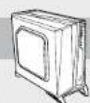
| Dimensions (L x W x H) | 518 x 220 x 474 mm |
| Weight | 6.2 kg |
| Material | Steel |
| Supported motherboard form factors | ATX, Micro-ATX, Mini-ITX |
| Storage slots | 2 x 2.5" or 3.5" (tool-free) + 1 additional 2.5" |
| Included fans | 3 x 120 mm LED (2 front, 1 rear) |
| Additional fan slots | 2 x 120 mm (top) |
| Maximum graphics card length | 380 mm |
| Maximum CPU cooler height | 156 mm |
| Maximum power supply length | 190 mm |
| Front panel connectors | 2 x USB 3.0, headphone/microphone jack, Power and Reset buttons |
| Side window | Yes, glass panel |
| Fan controller | Integrated, 3 speeds |
| Dust filter | Bottom (power supply) removable |
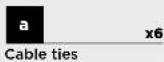
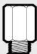
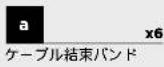
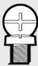
| Included accessories | Screws, cable ties, standoff |
| Maintenance | Cleaning dust filter, removing panels for access |
| Safety | Sturdy design, panels secured by screws |
| Reparability | Easy access via removable side panels and front panel |
Frequently Asked Questions - Carbide SPECAlpha CORSAIR
User questions about Carbide SPECAlpha CORSAIR
0 question about this device. Answer the ones you know or ask your own.
Ask a new question about this device
Download the instructions for your Desktop Computer in PDF format for free! Find your manual Carbide SPECAlpha - CORSAIR and take your electronic device back in hand. On this page are published all the documents necessary for the use of your device. Carbide SPECAlpha by CORSAIR.
USER MANUAL Carbide SPECAlpha CORSAIR
natural_image
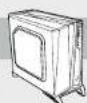
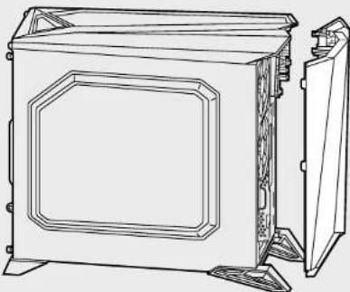
Line drawing of a desktop computer tower with front panel and rear legs (no text or symbols)CARBIDE SERIES*

CORSAIR
47100 Bayside Parkway • Fremont • California • 94538 • USA | corsair.com
© 2015 Corsair Components, Inc.
All rights reserved. Corsair, the sails logo, and Carbole Series are registered trademarks of Corsair in the United States and/or other countries. All other trademarks are the property of their respective owners. Product may vary slightly from those pictured.
PN: 49-001445 rev AA


SPEC-ALPHA

INSTALLATION GUIDE ■ GUIDE D'INSTALLATION
INSTALLATIONSANLEITUNG ■ Guía de Instalación
РУКОВОДСТВО ПО УСТАНОВКЕ ■ GUIA DE INSTALAÇÃO
インストールガイド
English: 5-14
Français: 15-24
Deutsch: 25-34
Español: 35-44
Россию: 45-54
Português: 55-64
日本人:65-74
CARBIDE SERIES SPEC-ALPHA
Table of Contents Case Specifications
Congratulations: 5
Case specifications: 5
Accessory kit contents: 7
Case features: 8
Removing the side panels: 9
Installing the motherboard: 9
Installing PCI-E/PCI card(s): 10
Installing the power supply: 10
Removing the front fascia: 11
Removing the top panel: 11
Installing HDDs and SSDs: 12
Installing additional SSDs: 12
Connecting the fan controller: 13
Installing the front I/O connectors: 13
Frequently asked questions: 14
Congratulations!
Thank you for purchasing the Carbide Series SPEC-ALPHA Mid-Tower Gaming Case.
With its bold, angular design the SPEC-ALPHA is designed to draw attention to itself. But those looks are far more than skin deep - the modern, optical drive free layout provides for fantastic cooling options, and built-in support for USB 3.0, SSDs, and a 3-speed fan controller give you the flexibility to build just about anything you want - and thanks to the large side panel window, show it off.
Length: 518mm
Width: 220mm
Height: 474mm
Weight: 6.2kg
Maximum GPU length: 380mm
Maximum CPU cooler height: 156mm
Maximum PSU length: 190mm

CARBIDE SERIES SPEC-ALPHA
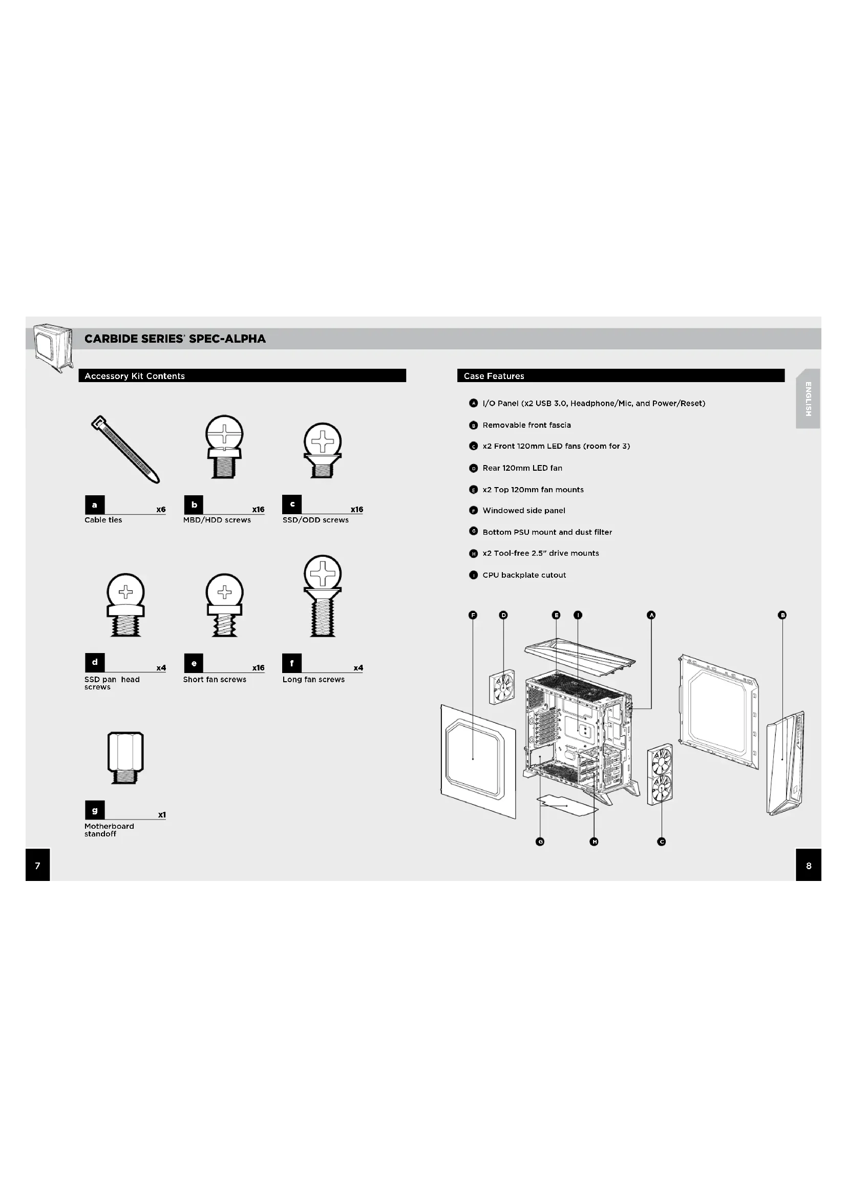
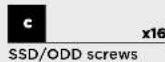
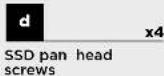
Accessory Kit Contents


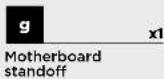
Case Features
I/O Panel (x2 USB 3.0, Headphone/Mic, and Power/Reset)
Removable front fascia
c x2 Front 120mm LED fans (room for 3)
D Rear 120mm LED fan
E x2 Top 120mm fan mounts
- Windowed side panel
Bottom PSU mount and dust filter
H x2 Tool-free 2.5" drive mounts
CPU backplate cutout

CARBIDE SERIES SPEC-ALPHA
1. Removing the Side Panels
Simply remove the thumbscrews then slide the side panels back and out.
Note: Corsair recommends removing both side panels and setting them aside when building your system to avoid accidental damage. Both side panels are interchangeable and should be removed to reduce clutter.
natural_image
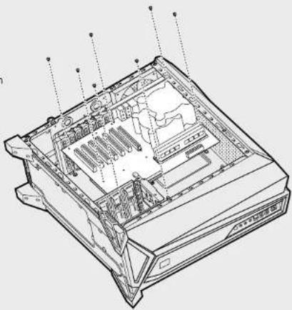
Technical line drawing of a computer tower case with internal components and mounting brackets (no text or labels)2. Installing the Motherboard
First, install your motherboard's I/O shield (see your motherboard's manual for guidance).
Align your motherboard with the pre-installed standoffs.
Use the provided screws to secure the motherboard to the motherboard tray.
natural_image
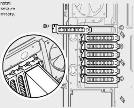
Technical line drawing of a computer tower internal structure (no text or labels)3. Installing PCI-E/PCI Card(s)
Remove slot cover, install expansion card, and secure with screw(s) as necessary.
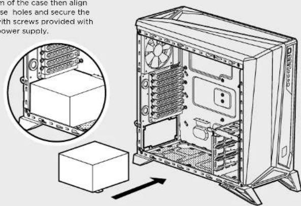
4. Installing the Power Supply
Position the PSU on the bottom of the case then align the case holes and secure the PSU with screws provided with your power supply.
CARBIDE SERIES SPEC-ALPHA
5. Removing the Front Fascia
To remove the front fascia, gently pull the front away from the case while pressing on the tabs securing it.
natural_image
Technical line drawing of a mechanical housing or enclosure with mounting feet and internal panel (no text or symbols)6. Removing the Top Panel
Remove the screws from the top rear of the case, and slide top panel backwards gently until you can lift it off.
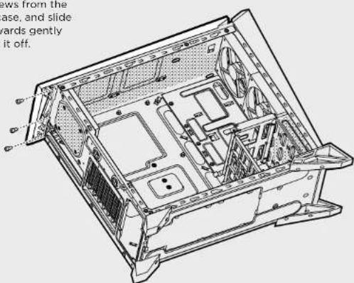
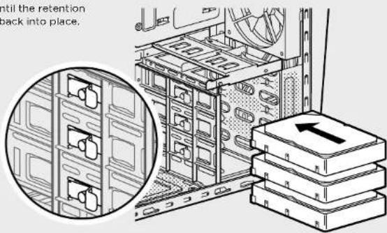
7. Installing HDDs and SSDs
Simply pull back retention arm and slide in the 2.5" SSD or 3.5" HDD until the retention arm snaps back into place.
8. Installing Additional SSDs
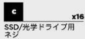
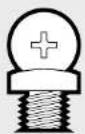
Align the 2.5" drive to the mid-panel of the case, and secure with the included screws from the accessory box.
CARBIDE SERIES SPEC-ALPHA
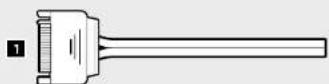
9. Connecting the Fan Controller
- Connect the SATA power connector to the PSU SATA power cable.
- Connect the 3 or 4-Pin fan connector to the case fan header.
- Push the fan speed selector button on your case to toggle fan speed.
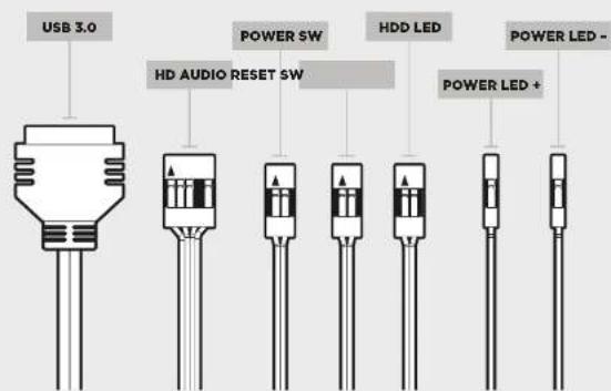
10. Installing the Front I/O Connectors
See your motherboard's manual for front panel header locations and pin-outs.
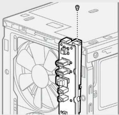
Frequently Asked Questions
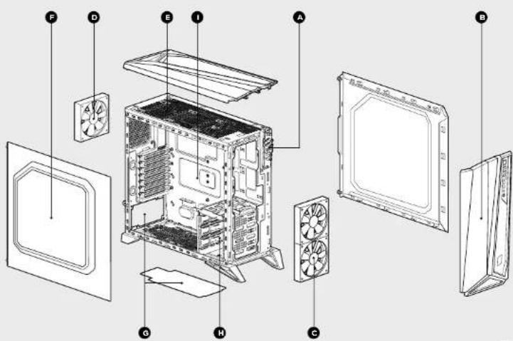
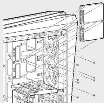
- How do I remove the I/O Panel?
If needed, you can uninstall your I/O panel by removing the front fascia (step 5) then unscrewing the 2 screws at each side of panel. (see drawing).
natural_image
Technical line drawing of a computer tower with fan and drive components (no text or symbols)- Does the polarity matter with the I/O panel's power and reset header? No, only the LED headers.
- Who should I contact if I received my case damaged or one of the fans is no longer working?
Please go to www.corsair.force.com and request an RMA so that we can replace the damaged part(s).
- Where can I mount a fan?
| Fan Mount Locations | |
| Front 2 x 140mm or 120mm (2 x 120mm included) | |
| Top 2 x 120mm | |
| Rear 120mm (included) | |
| Room 120mm | |
| Side x | |
| Mid x | |
To learn more about this case visit the product page at corsair.com

CARBIDE SERIES SPEC-ALPHA
Foire aux questions: 24
Félicitations!

CARBIDE SERIES SPEC-ALPHA

CARBIDE SERIES SPEC-ALPHA
natural_image
Technical line drawing of a computer case with internal components and mounting brackets (no text or symbols)natural_image
Technical line drawing of a computer tower with internal components and mounting points (no text or labels)3. Installation des cartes PCI-E/PCI
natural_image
Technical line drawing of a mechanical housing or enclosure with mounting feet and internal panel (no text or symbols)
CARBIDE SERIES SPEC-ALPHA
natural_image
Technical line drawing of a computer tower with fan and drive components (no text or symbols)
CARBIDE SERIES SPEC-ALPHA

CARBIDE SERIES SPEC-ALPHA
natural_image
Technical line drawing of a computer case with labeled components (no text or symbols present)2. Installation des Motherboards
natural_image
Technical line drawing of a computer tower internal structure (no text or labels)natural_image
Technical line drawing of a mechanical housing or enclosure with mounting feet and internal panel (no text or symbols)
CARBIDE SERIES SPEC-ALPHA
natural_image
Technical line drawing of a computer tower with fan and drive components (no text or symbols)
CARBIDE SERIES SPEC-ALPHA

CARBIDE SERIES SPEC-ALPHA
2. Cómo instalar la placa base
natural_image
Technical line drawing of a computer tower internal structure (no text or labels)3. Cómo instalar la(s) tarjeta(s) de PCI-E/PCI
natural_image
Technical line drawing of a mechanical housing or enclosure with mounting feet and internal panel (no text or symbols)
CARBIDE SERIES SPEC-ALPHA
natural_image
Technical line drawing of a computer tower with fan and drive components (no text or symbols)
CARBIDE SERIES SPEC-ALPHA

CARBIDE SERIES SPEC-ALPHA
natural_image
Technical line drawing of a computer tower with internal components and mounting points (no text or labels)3. Установка плат PCI-E/PCI
natural_image
Technical line drawing of a mechanical housing or enclosure with mounting feet and structural components (no text or symbols)
CARBIDE SERIES SPEC-ALPHA
natural_image
Technical line drawing of a computer tower with fan and drive components (no text or symbols)
CARBIDE SERIES SPEC-ALPHA

CARBIDE SERIES SPEC-ALPHA
1. Remover os painéis laterais
natural_image
Technical line drawing of a computer tower internal structure (no text or labels)3. Instalar placa(s) PCI-E/PCI
natural_image
Technical line drawing of a mechanical housing or enclosure with mounting feet and internal compartments (no text or symbols)6. Remover o painel superior
CARBIDE SERIES SPEC-ALPHA
natural_image
Technical line drawing of a computer tower with fan and drive components (no text or symbols)
CARBIDE SERIES SPEC-ALPHA
アクセサリーキットの内容


ケースの特徴

CARBIDE SERIES SPEC-ALPHA
1. サイドパネルの取り外し
2. マザーボードの取り付け

CARBIDE SERIES SPEC-ALPHA
5. 前面パネルの取り外し
natural_image
Technical line drawing of a mechanical housing or enclosure with internal components and mounting feet (no text or symbols)6. 天板の取り外し
natural_image
Technical line drawing of an internal computer case with visible internal compartments and mounting brackets (no text or symbols)7. HDD と SDD の取り付け

CARBIDE SERIES SPEC-ALPHA
9. ファンコントローラの接続
natural_image
Technical line drawing of a computer tower with fan and drive components (no text or symbols)
- CORSAIR
- SPEC-ALPHA
- CARBIDE SERIES SPEC-ALPHA
- Table of Contents Case Specifications
- Congratulations!
- Thank you for purchasing the Carbide Series SPEC-ALPHA Mid-Tower Gaming Case.
- Accessory Kit Contents
- Case Features
- Removing the Side Panels
- Installing the Motherboard
- Installing PCI-E/PCI Card(s)
- Installing the Power Supply
- Removing the Front Fascia
- Removing the Top Panel
- Installing HDDs and SSDs
- Installing Additional SSDs
- Connecting the Fan Controller
- Installing the Front I/O Connectors
- Frequently Asked Questions
- Félicitations!
- Installation des cartes PCI-E/PCI
- Installation des Motherboards
- Cómo instalar la placa base
- Cómo instalar la(s) tarjeta(s) de PCI-E/PCI
- Установка плат PCI-E/PCI
- Remover os painéis laterais
- Instalar placa(s) PCI-E/PCI
- Remover o painel superior
- アクセサリーキットの内容
- ケースの特徴
- サイドパネルの取り外し
- マザーボードの取り付け
- 前面パネルの取り外し
- 天板の取り外し
- HDD と SDD の取り付け
- ファンコントローラの接続
Brand : CORSAIR
Model : Carbide SPECAlpha
Category : Desktop Computer