USER MANUAL Ecofire Michela Palazzetti
INSTALLATION, USER AND MAINTENANCE MANUAL
WE'D LIKE TO THANK YOU FOR HAVING PURCHASED ONE OF OUR PRODUCTS AND CONGRATULATE YOU ON YOUR CHOICE.
TO MAKE SURE YOU GET THE MOST OUT OF YOUR NEW ECOFIRE STOVE, PLEASE CAREFULLY FOLLOW THE INSTRUCTIONS PROVIDED IN THIS MANUAL.

CHER CLIENT,
NOUS SOUHAITONS AVANT TOUT VOUS REMERCIER DE LA PRÉFÉRENCE QUE VOUS NOUS AVEZ ACCORDÉE EN ACHETANT NOTRE PRODUIT ET VOUS FÉLICITIONS POUR VOTRE CHOIX.
AFIN DE VOUS PERMETTRE DE PROFITER AU MIEUX DE VOTRE NOUVEAU POÊLE ECOFIRE, NOUS VOUS INVITONS À SUIVRE ATTENTIVEMENT LES INSTRUCTIONS REPORTÉES DANS CETTE NOTICE.

ESTIMADO CLIENTE,
natural_image
Five 3D human figures in various poses: walking, carrying bags, using wrench and tool (no text or symbols)
1.3 SCOPO E CONTENUTO DEL MANUALE
natural_image
A bag filled with small brown fuel cells, spilling out of a white surface (no text or symbols visible on the main subject)
Fig. 3.1
4 MOVIMENTAZIONE E TRASPORTO
Fig. 5.3
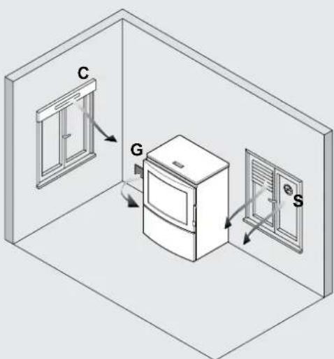
Fig. 5.4
STUFE DELLA SERIE "ERMETICA"
natural_image
Architectural cross-section diagram showing wall and brick wall components with directional arrows (no text or labels)
Fig. 5.6

Fig. 5.7
Fig. 5.9
6 INSTALLAZIONE
natural_image
Three 3D white figures with red wrench and magnifying glass, no text or symbols present

Fig. 6.1
natural_image
Diagram of a hand holding a plug with a circular component inserted into a wall, no text or symbols present
Fig. 6.2

natural_image
Diagram of a door with airflow arrows indicating movement, no text or symbols present
Fig. 6.3

natural_image
Hand holding a tool interacting with a circular object, labeled as Fig. 6.4 (no text or symbols on the object itself)
Fig. 6.4
USO E MANUTENZIONE


natural_image
3D illustration of a white figure holding red wrenches (no text or symbols)
natural_image
Diagram showing a wall-mounted switch and pipe connection, with circular elements arranged in a grid pattern (no text or symbols)
Fig. 8.1
natural_image
Illustration of a server unit with a large cylindrical device labeled 'CA' (no text or symbols on the device itself)
Fig.13.1
natural_image
Illustration of a hand holding a device with an arrow indicating rotation (no text or symbols present)

natural_image
Mechanical diagram showing a lever mechanism with motion arrows (no text or symbols)
Fig.15.1
natural_image
Technical line drawing of a wrench tool with no visible text or symbols
Fig.15.2
natural_image
Technical line drawing of a mechanical assembly with a curved pipe inserted into a housing (no text or symbols)

natural_image
Technical line drawing of a mechanical assembly with internal components and a handle (no text or symbols)
Fig.15.3
natural_image
Technical diagram of a structural joint or bracket assembly (no text or symbols visible)
natural_image
Technical diagram of a structural frame with an arrow indicating rotational motion (no text or symbols present)

natural_image
Technical diagram of a mechanical assembly with a curved tool and directional arrow (no text or symbols)
Fig.15.4

natural_image
Technical diagram of a mechanical assembly with a curved component and directional arrow (no text or symbols)

natural_image
Technical line drawing showing a door frame with an open drawer and a black arrow indicating direction (no text or symbols)
Fig.15.5

natural_image
Technical line drawing of a structural frame with curved elements inside, labeled Fig. 15.6 (no text or symbols on the diagram itself)
Fig.15.6
natural_image
Technical line drawing of a mechanical assembly with no visible text or symbols
Fig.15.7 A
natural_image
Technical line drawing of a mechanical assembly with no visible text or symbols
Fig.15.8 Fig.15.7 B
natural_image
Technical diagram of a vertical pipe system with a support structure and directional arrows (no text or labels)
Fig.15.9

Fig.15.10
15.4 MANUTENZIONE STRAORDINARIA
natural_image
Four 3D white figures holding red ribbon-like objects, no text or symbols present
1 INTRODUCTION 34
2 SAFETY WARNINGS 36
4 HANDLING AND TRANSPORT 37
16 DECOMMISSIONING AND DISPOSAL 58
INDEX
| 1 | INTRODUCTION 34 | 10 | FUNCTIONS AVAILABLE | 48 |
| 1.1 | SYMBOLS 34 | 10.1 | TIMER FUNCTION | 48 |
| 1.2 | INTENDED USE 34 | 10.2 | STANDBY FUNCTION | 50 |
| 1.3 | PURPOSE AND CONTENTS OF THIS MANUAL 34 | 10.3 | FROST PROTECTION FUNCTION | 50 |
| 1.4 | HOW TO KEEP THIS MANUAL 34 | 10.4 | "ECONOMY" FUNCTION | 50 |
| 1.5 | UPDATES TO THE MANUAL 34 | 10.5 | RESTARTING AFTER A POWER FAILURE | 50 |
| 1.6 | GENERAL INFORMATION 34 | 10.6 | READING THE OPERATING HOURS | 50 |
| 1.7 | MAIN REFERENCE STANDARDS 34 | 10.7 | STARTING AND SWITCHING OFF THE STOVE USING | 50 |
| 1.8 | PRODUCT WARRANTY 35 | | THE REMOTE DEVICE (only where available) | 50 |
| 1.9 | MANUFACTURER'S LIABILITY 35 | 10.8 | OPERATION WITH ROOM THERMOSTAT | 50 |
| 1.10 | INTENDED USERS 35 | 10.9 | "EASY CLEAN" FUNCTION | 50 |
| 1.11 | TECHNICAL SERVICE 35 | | | |
| 1.12 | SPARE PARTS 35 | 11 | MENUS | 51 |
| 1.13 | IDENTIFICATION LABEL 35 | | OPERATING SETTINGS MENU | 51 |
| 1.14 | DELIVERY OF THE STOVE 35 | 11.1 | TIMER MENU | 51 |
| | 11.2 | STOVE SETTINGS MENU | 51 |
| 2 | SAFETY WARNINGS 36 | | | |
| 2.1 | INSTALLATION WARNINGS 36 | 12 | ALARM MANAGEMENT | 53 |
| 2.2 | MAINTENANCE WARNINGS 36 | | | |
| 2.3 | WARNINGS FOR THE USER 36 | | | |
| | 13 | REMOTE CONTROL | 54 |
| 3 | FUEL SPECIFICATIONS 36 | | | |
| 3.1 | FUEL SPECIFICATIONS 36 | 14 | AIR DUCTS | 54 |
| 3.2 | STORING THE PELLETS 37 | | | |
| 4 | HANDLING AND TRANSPORT 37 | 15 | MAINTENANCE | 55 |
| 4.1 | REMOVING THE STOVE FROM THE PALLET 37 | 15.1 | SAFETY PRECAUTIONS 55 | |
| | 15.2 | STOVE CLEANING FUNCTION | 55 |
| | 15.3 | ROUTINE USER MAINTENANCE | 55 |
| 5 | INSTALLATION SITE PREPARATION 38 | 15.4 | SPECIAL MAINTENANCE | 58 |
| 5.1 | GENERAL INFORMATION 38 | | | |
| 5.2 | SAFETY PRECAUTIONS 38 | 16 | DECOMMISSIONING AND DISPOSAL | 58 |
| 5.3 | STOVE INSTALLATION SITE 38 | | | |
| 5.4 | COMBUSTION AIR 39 | | | |
| 5.5 | FLUE GAS EXHAUST 40 | | | |
| 6 | INSTALLATION 42 | | | |
| 6.1 | LEVELLLING THE STOVE 42 | | | |
| 6.2 | SYSTEM CONNECTIONS 42 | | | |
| 7 | STOVE DESCRIPTION 44 | | | |
| 7.1 | CONTROL PANEL 44 | | | |
| 7.2 | OPERATING PARAMETERS 44 | | | |
| 7.3 | ACCESSING THE MENUS 45 | | | |
| 8 | PRELIMINARY OPERATIONS 46 | | | |
| 8.1 | LOADING THE PELLETS 46 | | | |
| 8.2 | POWER SUPPLY 46 | | | |
| 8.3 | INITIAL SETTINGS 46 | | | |
| 9 | STOVE OPERATION 47 | | | |
| 9.1 | STARTING THE STOVE 47 | | | |
| 9.2 | MODIFYING THE PARAMETERS 47 | | | |
| 9.3 | SWITCHING OFF 47 | | | |
1 INTRODUCTION
PALAZZETTI heating appliances are built and tested in accordance with the safety requirements specified by the relevant European directives.
This manual is intended for owners, installers, users and maintenance personnel of the ECOFIRE series stoves and is an integral part of the product. If there are any doubts regarding the contents of this manual, or for any other explanations please contact the manufacturer or an authorised service centre, quoting the paragraph number in question.
No printing, translation and reproduction of this manual, in part or whole, is allowed without the permission of PALAZZETTI. The technical information, illustrations and specifications included in this manual may not be disclosed.
Do not operate the appliance if any of the instructions provided in the manual are not understood; if there are any doubts always contact specialist PALAZZETTI personnel for explanations.
PALAZZETTI reserves the ri ht to modify the technical and/or functional specifications of the stove at any time, without prior notice.
1.1 SYMBOLS
The most important points in this manual are highlighted by the following symbols:

INSTRUCTION: Instructions concerning correct stove operation and the responsibilities of operators.

IMPORTANT: This denotes very important information.

DANGER: This specifies the behaviour required to prevent accidents or damage to materials.
1.2 INTENDED USE

PALAZZETTI ECOFIRE appliances are stoves designed for heating the home, to be installed indoors, with automatic operation exclusively on wood pellets.
The stove can only operate with the firebox door closed.

Never open the door when the stove is operating.
The appliance is not intended for use by people (including children) with limited physical, sensorial or mental abilities, or without sufficient experience or knowledge, unless they are supervised or instructed on the use of the appliance by a person responsible for their safety.

The intended use of the stove described above and the configurations available are the only ones permitted by the manufacturer: never use the stove in any way not described in the instructions provided.
1.3 PURPOSEANDCONTENTSOFTHISMANUAL
The purpose of this manual is to provide the fundamental and essential rules for correct installation, maintenance and use of the product. Carefully following these rules will ensure a high level of stove safety and productivity.

natural_image
Five 3D human figures in various positions, including holding a red envelope and using wrenches (no text or symbols)
1.4 HOW TO KEEP THIS MANUAL
STORAGE AND REFERENCE
This manual must be kept with care and must be always available for reference by the user and by assembly and maintenance personnel.
The installation manual is an integral part of the stove.
DAMAGE OR LOSS
If required, an additional copy can be ordered from PALAZZETTI.
SALE OF THE STOVE
If the stove is sold the user must also provide the new owner this manual.
1.5 UPDATES TO THE MANUAL
This manual represents the state-of-the-art at the time the stove was introduced onto the market.
If information is requested from the manufacturer of the stove, always refer to the serial number and other identifying data shown on the product's identification label.
SPECIAL MAINTENANCE
Special maintenance operations must be carried out by qualified personnel who are authorised to work on the model of stove that this manual refers to.
RESPONSIBILITY FOR INSTALLATION
PALAZZETTI accepts no responsibility for the work carried out to install the stove; such responsibility lies with the installer, who is required to carry out checks on the flue and air intake and ensure installation is completed correctly. Furthermore, all safety standards required by relevant legislation in force in the country where the stove is installed must be complied with.
Use
The stove must only be used in compliance with the instructions provided in this manual, as well as with all safety standards required by relevant legislation in force in the country where the stove is installed.
1.7 MAIN REFERENCE STANDARDS
A) Directive 2006/95/EC: "Electrical equipment designed for use within certain voltage limits".
B) Directive 2004/108/EC: "Approximation of the laws of the Member States relating to electromagnetic compatibility".
C) Directive 89/391/EEC: "Introduction of measures to encourage improvements in the safety and health of workers at work".
D) Directive 89/106/EEC: "Approximation of the laws, regulations and administrative provisions of the Member States relating to construction
products".
E) Directive 85/374/EEC: "Approximation of the laws, regulations and administrative provisions of the Member States concerning liability for defective products."
F) Directive 1999/5/EC: "Radio equipment and telecommunications terminal equipment and the mutual recognition of their conformity".
G) UNI 14785/2006: "Residential space heat appliances fired by wood pellets – Requirements and test methods".
1.8 PRODUCT WARRANTY
In order to make use of the product warranty pursuant to Directive 1999/44/EC, users must fully comply with the instructions specified in this manual, and specifically:
• always use the stove within its operating limits;
• always carry out regular and thorough maintenance;
- allow the stove to be used by people of proven ability, attitude and suitably trained for the purpose;
- use original spare parts made specifically for the model of stove in question.
In addition, the following must be provided:
• tax receipt showing the purchase date.
• certificate of conformity of installation issued by the installer.
Failure to follow the instructions provided in this manual will render the warranty void.
1.9 MANUFACTURER'S LIABILITY
By providing this manual, PALAZZETTI declines all liability, both civil and criminal, direct or indirect, deriving from:
- installation not in compliance with the standards in force in the country concerned and with safety directives;
- partial or total failure to follow the instructions provided in this manual;
• installation by unqualified and untrained personnel;
- use not in compliance with safety directives;
- modifications and repairs on the stove that are not authorised by the manufacturer;
- use of spare parts that are not original or not specific for the model of stove;
- lack of maintenance;
- exceptional events.
1.10 INTENDED USERS
! The user of the stove must be a responsible adult with sufficient technical knowledge to carry out routine maintenance on the parts of the stove.

Make sure children do not play close to the stove while it's operating.
1.11 TECHNICAL SERVICE
PALAZZETTI has an extensive network of service
centres staffed by specialists trained directly by the company.
Please contact our head office or sales network for details of your nearest authorised service centre.
The company forum: http://forum.palazzetti.it offers access to a vast amount of information and allows users to exchange ideas, opinions and suggestions.
1.12 SPARE PARTS
Only use original spare parts.
Do not wait for components to become worn out before replacing them.
Replace a worn component before it malfunctions helps prevent accidents due to sudden breakages, which may cause serious harm to people and things.
Perform the periodical maintenance checks as described in the chapter on "Maintenance".
1.13 IDENTIFICATION LABEL
The serial number plate on the stove shows all the typical product data, including the manufacturer's details, the serial number and C€ markings.
1.14 DELIVERY OF THE STOVE
The stove is delivered packaged in a cardboard box or shrink-wrap and secured to a wooden pallet for handling by forklift and/or other equipment.
The following material is provided inside the stove:
- installation, user and maintenance manual;
- "product booklet" pertaining to the specific model;
- remote control (only on models where featured);
• tool for opening of the firebox door (only on models where featured).

2 SAFETY WARNINGS
2.1 INSTALLATION WARNINGS
Comply with the requirements specified in this manual.
The stove assembly and dismantling instructions are reserved exclusively for specialist technicians.
Users should always contact our service centre to request work to be performed by qualified technicians. Before having work performed by other technical personnel verify their effective technical competence.
Responsibility for work carried out in the place where the stove is installed lies with the user; the user is also responsible for making sure the installation checks are completed.
The user must abide by all local, national and European safety requirements.
The appliance must be installed on floors with a suitable load-bearing capacity.

Make sure that the flue and air intake duct arrangements correspond to the type of installation. Do not make any electrical connections using temporary or uninsulated cables.
Make sure the electrical system is earthed correctly.
Before starting to assemble or dismantle the stove, the installer must heed the safety precautions required by law, specifically:
A) do not work in adverse conditions;
B) always be in a fit mental-physical state for working and make sure that personal protective equipment is in perfect working order;
C) always wear safety gloves;
D) always wear safety shoes;
E) always use electrically insulated tools;
F) make sure that the area being used for assembly and dismantling is clear of any obstacles.
2.2 MAINTENANCE WARNINGS

- Comply with the requirements specified in this manual.
- Use always personal protective equipment and other means of protection.
- Before starting any maintenance work make sure that the stove, if it had been operating, has cooled down.
- If even just one of the safety devices is not calibrated or not working, the stove must be considered out-of-service.
- Disconnect power before working on electrical or electronic parts and connectors.
2.3 WARNINGS FOR THE USER

• Prepare the stove installation site in accordance with local, national and European regulations.
- As the stove is a heating appliance it has very hot outside surfaces. For this reason maximum care must be paid during operation, specifically:
-
do not touch or get too close to the glass door to avoid getting burned;
-
do not touch the flue;
• do not perform any type of cleaning;
• do not remove the ash;
• do not open the glass door;
-
do not open the ash bin (where featured);
• make sure children keep away from the stove.
-
Comply with the requirements specified in this manual.
- Follow the instructions and warnings highlighted on the metal labels affixed to the stove.
- These labels are safety devices, therefore they must always be perfectly legible. If damaged or illegible they must be replaced, contacting the manufacturer for an original spare label.
- Only use fuel compliant with the specifications shown in the corresponding chapter of this manual.
- Strictly follow the routine and special maintenance plan.
- Do not use the stove without first having performed the daily inspection as specified in the chapter on "Maintenance" in this manual.
- Do not use the stove in the event of malfunctions, suspected breakage or unusual noises.
- Do not pour or spray water onto the stove when operating or to extinguish the flame in the burn pot.
- Do not switch the stove off by unplugging the power cord.
- Do not rest your weight on the open door as this may affect stability.
- Do not use the stove in any way as a support or anchor.
- Do not clean the stove until the structure and ash have completely cooled down.
- Touch the door only when the stove has cooled down.
- Perform all operations without haste, in such a way as to ensure maximum safety.
- In the event of fire in the chimney switch the stove off using the procedure described in par. 9.3.
- In the event of stove malfunctions due to flues with incorrect draught, clean the flue according to the procedure described in par. 15.4.
• The flue must be cleaned as described in paragraph 15.4.
- Do not touch the painted parts during operation to avoid damaging the paintwork.
3 FUEL SPECIFICATIONS
3.1 FUEL SPECIFICATIONS
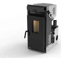
Pellets (Fig. 3.1) are made from various types of mechanically compacted wood in compliance with environmental protection standards. Pellets are the only fuel that can be used on this type of stove.
The efficiency and heat output of the stove may vary in relation to the type and quality of pellets used.
The pellet stove requires pellets with the following
characteristics:
- diameter \~ 6 mm;
- max. length 30 mm;
- max. moisture content 6 - 9%.
The stove has a pellet hopper with the capacity specified in the technical data table in the Product Booklet enclosed.
The pellet hopper is located at the top of the stove. It must always be able to be opened to load the pellets, and must remain closed during operation.

Due to temperature control requirements, operation on traditional wood is not possible.

The stove must not be used as a rubbish incinerator.
3.2 STORING THE PELLETS
The pellets must be kept in a place that's dry and not too cold.
It's suggested to keep some sacks of pellets in the same room where the stove is installed or an adjacent room, as long as the temperature and humidity are acceptable.
Damp and/or cold pellets (5°C) reduce the fuel heat value and mean the burn pot (unburned material) and firebox will need to be cleaned more frequently.

Pay special care when storing and handling the sacks of pellets. Make sure these are not crushed to prevent the pellets from becoming sawdust.
Sawdust introduced into the hopper may block the pellet feed system.
Use of poor quality pellets may affect normal pellet stove operation and render the warranty void.
The features of the pellets must comply with the requirements of EN 14961-2.
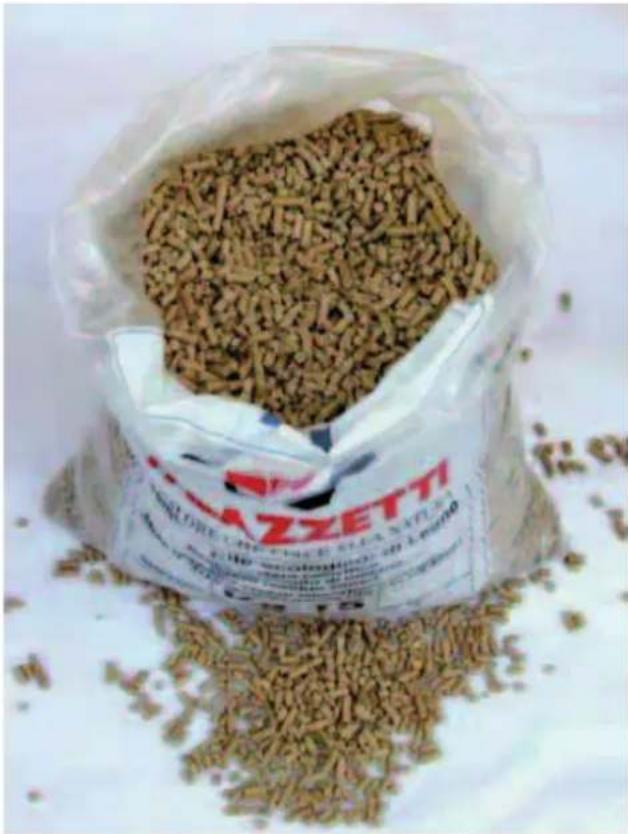
natural_image
A bag filled with small brown fuel rods, spilling out of a white surface (no visible text or symbols)
Fig. 3.1
4 HANDLING AND TRANSPORT
The stove is delivered complete with all parts included.
Beware of the tendency of the stove to tip over.
The stove's centre of gravity is towards the front of the appliance.
Always keep this in mind when moving the stove on the transport pallet.
When lifting avoid jolts or sudden movements.
Make sure that the forklift capacity exceeds the weight of the stove being lifted.
The operator of the forklift or other hoisting equipment is responsible for lifting the loads.

Prevent children from playing with the packaging components (e.g. film and polystyrene). Danger of suffocation!
4.1 REMOVING THE STOVE FROM THE PALLET
To remove the stove from the transport pallet follow the instructions shown in the "Product Booklet" enclosed.
5 INSTALLATION SITE PREPARATION
The following paragraphs provide instructions that must be complied with in order to ensure maximum efficiency of the product purchased.
The following instructions are however subordinate to compliance with any national, regional and local laws and standards in force in the country where the product is installed.
5.2 SAFETY PRECAUTIONS
Responsibility for work carried out in the place where the stove is installed lies with the user; the user is also responsible for making sure the installation checks are completed.
The user must abide by all local, national and European safety requirements.
The appliance must be installed on floors with a suitable load-bearing capacity.
The stove assembly and dismantling instructions are reserved exclusively for specialist technicians. Users should always contact our service centre to request work to be performed by qualified technicians.
Before having work performed by other technical personnel verify their effective technical competence. Before starting to assemble or dismantle the stove, the installer must heed the safety precautions required by law, specifically:
A) do not work in adverse conditions;
B) always be in a fit mental-physical state for working and make sure that personal protective equipment is in perfectly working order;
C) always wear safety gloves;
D) always wear safety shoes;
E) always use electrically insulated tools;
F) make sure that the area being used for assembly and dismantling is clear of any obstacles.
5.3 STOVE INSTALLATION SITE
Fig. 5.1 and the corresponding table show the minimum clearances from combustible materials and objects expressed in centimetres that must be observed when positioning the stove; for non-flammable walls/objects, these clearances can be halved.
A) Adjacent wall.
B) Rear wall.
C) Side wall.
D) Protective flooring.
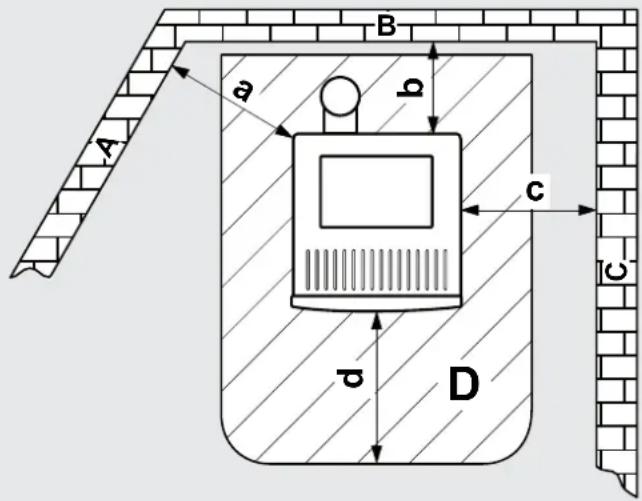
Fig. 5.1
| Type of pellet stove | a | b | c | d |
| Corridoio series | 60 | 2 | 60 | 30 ÷ 50 |
| Angolo series | 30 ÷ 50 | 2 | 2 | 30 ÷ 50 |
| Silent series | 20 | 20 20 | 30 ÷ 50 | |
| Ermetica series | 20 | 20 20 | 30 ÷ 50 | |
| Classica series | 20 | 20 20 | 30 ÷ 50 | |
ChecT the type of stove in the product booTlet enclosed.
Protect all structures that may catch fire if exposed to excessive heat.
Floors made from flammable materials such as: wood, parquet, linoleum, laminates or carpets must be protected by a suitably-sized fireproof base underneath stove. Such base may be made from steel, slate, glass or stone and must cover the floor in the part underneath the stove and the flue attachment, and must extend at least 50 cm at the front.
The manufacturer declines all liability for any alterations to the characteristics of the material making up the floor underneath the protective base.
Any elements made from wood (e.g. beams) or other combustible material located near the stove
should be protected with fireproof material.
Flammable walls or elements must be kept at least 150 cm away from the stove.
! Leave enough clearance for maintenance work.
Make sure the minimum distance from flammable materials (x) is observed, as shown on the pipes used to make up the flue or chimney (Fig. 5.2).
Pi = Parete infiammabile
! During operation the stove takes in a certain amount of air from the room where it's installed (except for the "Ermetica" series products that can take in air directly from the outside); this air must be replaced through an opening to the outside from the room (Fig. 5.3 - PA = Fresh air vent).
If the wall behind of the stove is an outside wall, make an opening for drawing in combustion air around 20-30 cm above the floor, observing the dimensions shown on the product data sheet at the end of this booklet.
A permanent non-closable vent cover must be placed on the outside of the opening; in especially windy areas or places exposed to bad weather, install rain and wind protection elements.
Make sure that the air vent is located in such a way that it can't be accidentally obstructed.
If it's not possible to make a fresh air opening in the wall behind the stove (not a perimeter wall), an opening must be made on the wall in the room where the stove is installed that faces the outside.
If no fresh air opening can be made in the room, it can be made in an adjacent room as long as the two rooms are connected by a ventilation grill (Fig. 5.4 - C = Shutter box, G = Grill, S = Shutters)
Standard UNI 10683 prohibits combustion air being drawn in from garages, combustible material stores or places where there is a fire risk.
If there are other heating appliances in the same room, the fresh air vents must guarantee the required volume of air for correct operation of all the appliances.
If one or more exhaust fans (range hoods) are installed and operating in the room where the stove is located, combustion problems may occur due to a lack of combustion air.
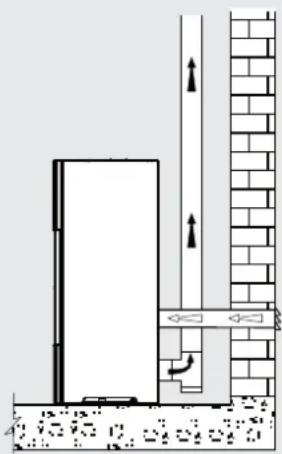
"ERMETICA" SERIES STOVES
The "Ermetica" series pellet stoves allow the following possible installation alternatives:
- ducted combustion air using a coaxial pipe to discharge the flue gas and take in fresh air; consequently no fresh air vent is needed in the room (Fig. 5.5 A, B=Air intake C, D=Flue gas
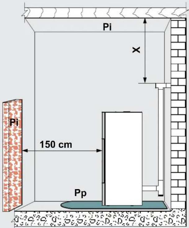
Fig. 5.2

Fig. 5.3

Fig. 5.4
outlet);
- connect the stove combustion air intake to the fresh air opening using a special pipe (Fig. 5.6).
The stove operates with negative pressure in the combustion chamber, and consequently the flue gas discharge must be airtight.
The stove must be connected to its own separate flue gas exhaust system capable of ensuring adequate atmospheric dispersion of the combustion byproducts.
The components making up the flue gas exhaust system must be suitable for the specific operating conditions and bear the CE mark.
The pipes used to discharge the flue gas must have a nominal diameter of 8 cm with gaskets (up to 5 metres in length), or 10 cm with gaskets (for lengths exceeding 5 metres) (Fig. 5.7).
For the flue dimensioning use 0Pa.
The flues should be suitably insulated (e.g. using rock wool) or made using double wall steel pipes, except for the initial vertical section inside the room.
An initial vertical section measuring a minimum of 1.5 metres is required to ensure correct flue gas exhaust.
There should be at least three changes in direction along the flue, in addition to the flue connection at the rear of the stove, using 45 or 90° angle connectors or 'T' connectors.
Use always a 'T' connector with inspection cap on all horizontal or vertical changes in flue direction.
The maximum length of horizontal sections is 2-3 m with an upwards slope of 3-5% (Fig. 5.7).
Anchor the flues to the wall using special collars.
The flue gas exhaust attachment MUST NOT BE connected to:
- a chimney used by other heat generators (boilers, stoves, fireplaces, etc.....);
- air exhaust systems (range hoods, vents, etc.....) even if these are ducted.
Shut-off or draught valves must not be used.
Combustion byproducts must be discharged through the roof.
If the flue is longer than 5 metres and there is insufficient draught (many changes in direction, unsuitable discharge terminal, etc.) flue gas exhaust may be less than optimum. In these cases, the operating parameters will need to be modified (flue gas exhaust and pellet load) to adapt the stove to the actual characteristics of the flue. Contact technical service for this procedure.
"ERMETICA" SERIES STOVES
For "Ermetica" series pellet stoves a special coaxial pipe can be used to both discharge the flue gas and duct the combustion air from the outside (Fig. 5.5 A, B=Air intake C, D=Flue gas outlet).
5.5.1 Dischargethroughroofusingatraditionalchimney
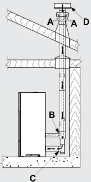
Fig. 5.5
natural_image
Architectural cross-section diagram showing wall and brick wall components with directional arrows (no text or labels)
Fig. 5.6
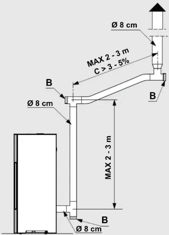
Fig. 5.7
The chimney used to discharge the flue gas must be made in accordance with standards UNI 10683 - EN 1856-1-2 - EN 1857 - EN 1443 - EN 13384-1-3 - EN 12391-1 both as regards the dimensions and the construction materials used.
DAMAGED chimneys made from unsuitable material (asbestos cement, galvanised steel, etc.... with a rough and porous inside surface) are prohibited by law and affect proper stove operation.
The flue gas can be discharged through a traditional chimney (Fig. 5.8) as long as the following rules are observed:
- check the conditions of the chimney; old chimneys should be renovated by introducing steel piping with suitable insulation (rock wool, vermiculite).
- the flue gas can be discharged directly into the chimney only if the latter has a maximum cross-section of 15 × 15 cm or diameter of 15 cm and features an inspection opening.
! For larger chimneys, suitably insulated steel pipes need to be inserted on the inside (diameter according to the length) (Fig. 5.9).
Makes sure connections to brick chimneys are suitably sealed.
Avoid contact with combustible materials (e.g. wooden beams) and in any case insulate these using fireproof material=
! If the flues run through wooden roofs or walls, special certified pass-through kits need to be used, available on the market.
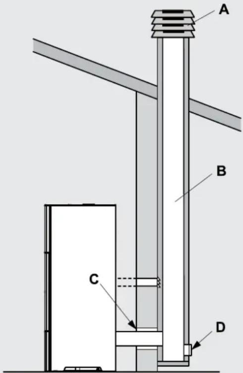
Fig. 5.8
A) Chimney pot with wind protection
B) Maximum cross-section of 15 × 15 cm or diameter of 15 cm and maximum height of 4-5 metres
Fig. 5.9
1) Vermiculite and/or rock wool.
2) Steel pipes.
3) Closure panel.
6 INSTALLATION

natural_image
Three 3D white figures with red tools, one carrying a sack and the other holding a wrench (no text or symbols visible)
The stove must be installed by qualified personnel in compliance with EN 10683.
6.1 LEVELLING THE STOVE
The stove must be levelled by adjusting the feet (where featured), then checked using a spirit level (Fig. 6.1).
A B = Spirit level
6.2 SYSTEM CONNECTIONS
6.2.1 Electrical connection
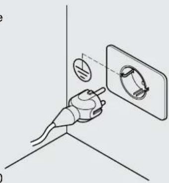
The stove is connected to the electrical system simply using the plug supplied.
The electrical connection (plug) must be easily accessible when the stove is installed.
! If the power cord is damaged it must be replaced by the technical service or a qualified technician, to prevent any kind of risk.
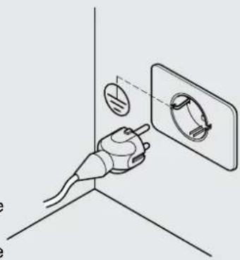
6.2.1.1 Earth
The system must be earthed and fitted with a residual current circuit-breaker in accordance with legislation in force (Fig. 6.2).
! The flue must have its own earth connection.
6.2.1.2 Room thermostat
The thermostat is connected to the appropriate inputs of the circuit board, as shown in the wiring diagram in the attached "Product Manual".
6.2.1.3 Remote device (only for models where fitted)
The remote device is connected to inputs 1 and 2 on terminal block CN7 on the electronic board. (only in the board where terminal block CN7 has 10 inputs)
The device must be configured as NORMALLY OPEN and have an adjustable differential.
When activated (contact opens) the stove will be switched off or on.
After installing the remote device, the stove must be started the first time from the control panel.

Fig. .1
natural_image
Diagram of a hand holding a plug with a circular component inserted into a wall socket (no text or symbols)
Fig. 6.2
6.2.2 Connection to an air distribution system
(only for ducted models or provided with ducting kit)
Ducted models can be connected to a hot air distribution system. The pipes used should preferably be circular with a smooth inner surface and suitably insulated to avoid heat loss.

&or ducted stoves or models ready to fit a ducting kit that are not connected to a hot air distribution pipe, make sure the deflector is positioned so as to deviate the hot air into the room where the stove is installed.
DUCTED STOVES
Using the tool supplied or the air deflector lever (based on the model), the flow of hot air can be deviated from the room where the stove is installed to the ducting, and vice-versa (Fig. 6.3).
To connect the stove to the ducting system, remove the cap by unscrewing the two fastening screws that secure the duct closure cap on the rear of the stove (Fig. 6.4).
STOVES READY TO FIT A DUCTING KIT
To assemble the ducting kit see the instructions provided with the kit.
The flow of hot air can be deviated from the room to the ducting using the tool supplied with the kit to adjust the deflector control located on the front of the stove.

Fig. .3
natural_image
Illustration of a hand using a tool to observe a circular object on a 3D surface, labeled Fig. .4 (no text or symbols on the diagram itself)
Fig. .4
USE AND & MAINTENANCE

natural_image
3D figure holding a red folder, no text or symbols visible

natural_image
3D illustration of a white figure holding red wrenches (no text or symbols)
7 STOVE DESCRIPTION
Before reading this booklet, check the description of the stove provided in the "Product Booklet" enclosed.
7.1 CONTROL PANEL
The panel (Fig. 8.1) consists of a backlit LCD display, the on button ON, off button OFF and two menu buttons (▲ and ✕).
The panel is used to:
- start and switch off the stove;
- adjust operation;
- set the management and maintenance programs.
The display shows three stove operating stages:
1) OFF: means that the stove is not on or is cooling down.
2) AWAITING FLAME: and FLAME ON indicate that the stove is starting.
3) FIRE ON: indicates that the stove is on and is heating.
The stove operating parameters can be set for all three stages.
These parameters will only be active when the stove is on, as the IGNITION and OFF stages are managed automatically.
The stove settings can be made using three different interfaces:
- Scrolling: the control parameters are displayed one at a time in sequence on the second row of the panel.
- Compressed: all the control parameters are displayed at the same time on the second row of the panel.
- Easy+it's possible to set only the desired room temperature.
The stove is delivered with scrolling mode active.
The user can change mode from scrolling to compressed or easy at any time (see par.11.33 - "MENU TYPE").

Holding one of the two arrow buttons speeds up the scroll rate.
7.2 OPERATING PARAMETERS
When on, the stove automatically adapts its operation based on the set values, as shown on the display:

Fig. 7.1
POWER [P]: This represents the stove's heat output or power level.
The possible values are A (automatic), 1 (minimum), 2, 3, 4, 5 (maximum).
If setting the value "A" the stove will attempt to heat the room to the set temperature, managing the power level completely automatically.
FAN [V]: This represents the hot air fan speed. The possible values are A (automatic), 1 (minimum), 2, 3, 4, 5 (maximum).
If setting the value "A" the stove will manage the fan speed automatically based on the heat output.
In automatic mode the stove may temporarily operate the fan at maximum speed so as to remove any excess accumulated heat; in this case the display shows "E" correspondin to the fan speed.

Silent series stoves (natural convection) do not feature the parameter relating to the air fan.
SET ROOM T.: This indicates the desired room temperature.
The temperature value can be set in the range between 10^ and 40^ ; alternatively, the following values can be set:
L (low): the stove will operate at minimum output;
H (high): the stove will operate at the set output or power level.
When the room temperature reaches the set point, the stove will adjust operation automatically so as to maintain the temperature while consuming the least possible fuel, and the display will show+
| PARAMETERS | COMPRESSED INTERFACE | SCROLLING INTERFACE | EASY INTERFACE |
| PowerFan speedRoom temp./Set temp. | “P=...”“V=...”“.../...” (Room temp./Set temp.) | “POWER =...”“FAN SPEED =...”“SET ROOM T. =...” | “.../...” |
| COMPRESSED MENU EASY MENU | SCROLLING MENU |
| The two temperatures displayed (room and set) will flash | First row: "MODULATION"Second row: in addition to the stove operating parameters, the message "THERMOSTAT ON" will be shown cyclically |
This paragraph illustrates the procedure for accessing the menus and selecting the various functions.
Fig 7.2 represents the display, highlighting the elements that can be displayed.
Function: the description of the available function or menu is shown in the centre in upper case.
Control: there may be a symbol ( ^a / " + " . and " / " - " ) or letters in italics ("ok", "x") shown in the corners (near any of the four buttons); the action in question is activated by pressing the corresponding button.
Actions:
ok: pressing the ON button confirms the changes made.
x: pressing thetton exits the current display and returns to the previous screen.
+/+: pressing the button scrolls the various screens of the display or increases the value of the parameter.
√/-: pressing the ▼ button scrolls the various screens of the display or decreases the value of the parameter.

1) Press the ▲ and ▼ buttons together; the display will show: OPERATING SETTINGS MENU Fig 7.3.
2) Press ▲ to scroll the other menus: TIMER MENU, STOVE SETTINGS MENU.
3) To ENTER the menu: scroll to the desired menu and then press ON (ok).
To exit the menu and return to the previous screen: press OFF (x).
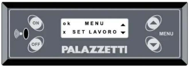
Fig. .2

Fig. .3
8 PRELIMINARY OPERATIONS

8.1 LOADING THE PELLETS
The first operation to be performed before starting the appliance is to fill the hopper with fuel (pellets%=
The pellets are loaded into in the hopper using a scoop.
Do not empty the sack directly into the hopper so as to avoid loading sawdust or other foreign bodies that may affect proper stove operation and avoid spilling pellets outside of the hopper.
Make sure the hopper lid is well closed again after having loaded the pellets.
8.2 POWER SUPPLY
Plug the stove into the mains power supply, move the power switch at the rear of the stove to position "I" (Fig. 8.1). If the connections are correct the stove will emit a series of intermittent beeps, the display will come on and the message "PALAZZETTI ECOFIRE" will be shown. After 2 seconds the display will show "OFF" and the second row will show the operating parameters: POWER, AIR FAN, SET ROOM T..

On Silent series stoves (no ventilation) the "air fan" parameter is not featured.
! If not using the appliance for an extended period, the switch at the rear of the stove should be moved to position (O).
8.3 INITIAL SETTINGS
The language, current date and time need to be set before using the stove.
8.3.1 language setting
Go to the "STOVE SETTINGS MENU" following the "Procedure for accessing the menus" described in paragraph 7.3 and press OK.
1) Scroll the submenus using the ▲ or ▼ button
2) Use the ON button to select the "LANGUAGE" menu
3) Select the desired language using the ▲ or ▼ button
4% Confirm the selection by pressing _ON ("ok")
5) Press OFF ("x") to exit the submenu (press the same button again if necessary to go back another menu level).
8.3.2 Time setting
Go to the "STOVE SETTINGS MENU" following the

natural_image
Diagram showing a wall-mounted switch and pipe connection, with circular elements arranged in a grid pattern (no text or symbols)
Fig. .1
"Procedure for accessing the menus" described in paragraph 7.3 and press OK.
4) Scroll the submenus using the ▲ or ▼ button
5) Use the ON button to select the "TIME" menu
6) Select the current day using the ▲ or ▼ button and confirm by pressing °("ok")
7) Select the current hours using the ▲ or ▼ button and confirm by pressing ON ("ok")
8) Select the minutes hours using the ▲ or ▼ button and confirm by pressing □("ok")
9) Press OFF ("x") to exit the submenu (press the same button again if necessary to go back another menu level).
8.3.3 Date setting
Go to the "STOVE SETTINGS MENU" following the "Procedure for accessing the menus" described in paragraph 7.3 and press OK.
4) Scroll the submenus using the ▲ or ▼ button
5) Use the ON button to select the "DATE" menu
6) Select the current day, month and year desired using the ▲ or ▼ button and confirm each selection by pressing ON ("ok")
7) Press OFF ("x") to exit the submenu (press the same button again if necessary to go back another menu level).
9 STOVE OPERATION
9.1 STARTING THE STOVE
To start the stove hold the * button for several seconds.
The display shows the message “AWAITING FLAME”. This stage of operation is automatic and managed completely by the stove itself. During this stage the flame will be ignited and the stove will reach steady operating conditions.
Subsequently, the display will show the message "FLAME ON".
The stove will then automatically switch to the "FIRE ON" stage when the temperature is sufficient for correct operation (using the same operating parameters as when the stove was last started).
! Automatic stove ignition: the stove comes with an automatic device that starts the pellet stove without using other traditional fire lighters.
Avoid lighting the flame manually if the stove's automatic ignition system is not working correctly.
! When the stove is started the first time, unpleasant odours or smoke may be generated, caused by evaporation or drying of certain materials used. This phenomenon will gradually disappear.
The room should be well ventilated when starting the stove the first few times.
9.2 MODIFYING THE PARAMETERS
The stove operating parameters, described in paragraph 7.2, can be modified by the user in three different ways based on the type of interface selected (scrolling, compressed or easy).
With this interface configuration, the parameters are shown cyclically on the display. When needing to modify a value, wait for the desired parameter to be displayed (Power, Fan, Set Room T.) and use the ▲ button to increase the value or the ▼ button to decrease it.
When the stove is in the "FIRE ON" stage (shown on the first row of the display), to modify the parameters simply press the ON button to access the menu for modifying the parameters, Fig. 9.1.
The display will show the parameters (P, F, T) and four symbols indicating the functions of the menu buttons (OK, X, +, -).
To move from one parameter to the next press ON ("OK"). The selected parameter will flash, then to modify the value press ▲ ("+") or ▼ ("-").
Once all the parameters have been set, press ("X") to exit the menu.
To modify the parameters on the compressed menu when not in the "FIRE ON" stage, first access the "OPERATING SETTINGS MENU" as illustrated in paragraph 11.1.

The values set will be retained until next modified, even when the stove is switched off or unplugged from the power supply.

In this configuration you can only set the desired room temperature using the up and down buttons. Fan speed and power can not be changed. They are automatically set on "A".
9.3 SWITCHING OFF
To switch the stove off hold the OFF button for a few seconds. The display will show the message "FINAL CLEANING" and the stove will activate, for a few minutes, an automatic procedure to shut down in complete safety.

To start the stove again it's recommended to wait for the stove to cool down completely.

If attempting to start the stove again the display may show the message "WAIT TO END CLEANING", asking the user to wait until the stove has shut down completely.

The stove should only be switched off following the procedure described above. Never switch the stove off by unplugging it from the power supply.
9.3.1 Empty burn pot warning
The purpose of this warning is to ensure that the burn pot is clean before ignition and consequently guarantee the best possible stove operation.

Never pour the contents of the burn pot into the pellet hopper.
After having cleaned the burn pot reset the warning by pressing and holding the OFF button.
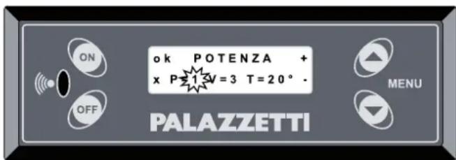
Fig. .1
10 FUNCTIONS AVAILABLE
10.1 TIMER FUNCTION
This function is used to set custom programs for automatically starting and/or switching off the stove.
Go to the "TIMER MENU" following the "Procedure for accessing the menus" described in paragraph 7.3.
The first screen shows the setting for program "P1"=
Up to 6 programs can be set (P1 to P6).
Press the button or the button to display the different programs.
SETTING THE PROGRAMS
Press the button to scroll and access the parameters for the desired program.
Press the button or ▼ button to scroll the settings within the program.
Press the button to confirm the data or OFF to exit without confirming the data=
The top row of the menu shows 3 parameters (Fig.10.1):
The first parameter on the left can be set as:
a) "OFF" to deactivate the program.
b) "ON" to activate the program using the values set in the OPERATING SETTINGS MENU.
c) a value between 10^ C and 30^ C to activate the program with the set temperature.
In the first two cases the second row of the display will show "Program", in the third case this message will alternate with the message "Set room t." (set room temperature).
The second parameter (in the centre% defines what time the stove will start.
Select the desired time and press ON or alternatively select "OFF" (scrolling the times this comes between 23.50 and 00.00) to disable the start time. The display will show: "Start Timer".
The third parameter (on the right% defines what time the stove will switch off.
Select the desired time and press ON or alternatively select "OFF" (scrolling the times this comes between 23.50 and 00.00) to disable the switch-off time. The display will show: "Start Timer".
If the start time is set as OFF, timed starting will be disabled.
If the switch-off time is set as OFF, timed switch-off will be disabled.
This option is useful for programming the stove to either start only or switch off only.
Moving to the second row (ON button) accesses the days of the week (M,...,Su) to be combined with the program.
Use the button to scroll the days and enable

each day as desired using either of the two arrow buttons. An icon representing a solid dot “●” will be shown to the left of the selected day.

When at least one program is active, the display will show a solid dot “●”.

Fig.10.1
EXAMPLES:
Example 1
1) Press the ▲ end buttons together; the display will show: OPERATING SETTINGS MENU (Fig.10.2).
2) Press ▲ and move to: TIMER MENU.
3) Press ON to select this menu.
4) Use the arrow buttons ( ▲ or ▶*) to choose the desired program (e.g. "P2") and select this by pressing ON.
5) Press the ▲ button or □ button to scroll the settings within the program.
6) Go to the first parameter in the top left that will be flashing, confirm by pressing on and set the value 25^ using the arrow buttons.
7) Confirming by pressing ON this will automatically move the cursor to the second parameter that defines the time the stove will start; use the arrow buttons to set 19:00.
8) Confirming by pressing ON this will automatically move the cursor to the third parameter that defines the time the stove will switch off; use the arrow buttons to set OFF (meaning the stove needs to be switched off manually).
9) Confirming by pressing this will automatically move the cursor to the second row and the various days of the week will start flashing; use the button until "F" (Friday) is flashing and then select this by pressing ▲. Repeat the same step to select "S" (Saturday) and "Su" (Sunday)
The result will be as illustrated in Fig.10.3. i.e. program "P2" has been enabled (having entered "25", the stove will try to heat the room to 25°C with automatic heat output and fan operation).
In this case the stove will switch on every Friday, Saturday and Sunday at 19.00. Having set the switch-off time to OFF, the user plans to switch the stove off manually (for example, before going to bed).
Example 2
In the example in Fig.10.4 program "P1" has been enabled (having entered "ON" the stove will use the same operating parameters as when last started).
In this case the stove will switch on every Monday and Thursday at 15.30 and will switch off at 22.00.

Fig.10.2
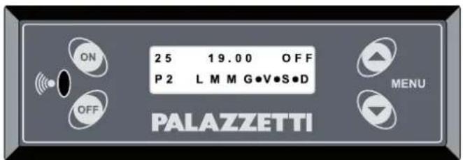
Fig.10.3
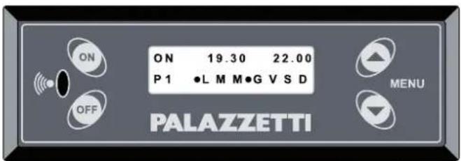
Fig.10.4
Exemple 3
The example in Fig.10.5 represents the same program as the previous example, however this has been disabled by selecting OFF (for example, the user knows they'll be away on the weekend and doesn't want the stove to start automatically).
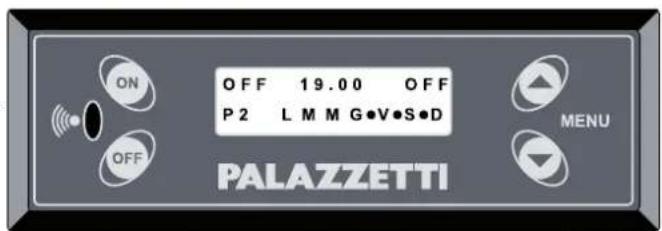
Fig.10.5
USE AND & MAINTENANCE
10.2 STANDBY FUNCTION
During operation (i.e. when the stove is on and in steady operating conditions) the stove can be switched off when reaching the set room temperature (SET ROOM T.) and start again when reaching the set minimum room temperature (START TEMP.).
To enable this function, go to the "STOVE SETTINGS MENU" following the "Procedure for accessing the menus" described in paragraph 7.3 and press . Use the arrow buttons to scroll until the display shows "STAND-BY" and then press .
Two parameters can be set:
- The first - ON/OFF - enables or disables the function;
- The second defines the temperature for restarting the stove.
When this function is active, the display shows the “” symbol.
"STAND-BY" is displayed when the room temperature is higher than the set "START TEMP.".
10.3 FROST PROTECTION FUNCTION
When the stove is off this function ensures the stove maintains the set room temperature (useful at night).
To access this function go to the "STOVE SETTINGS MENU" using the "Procedure for accessing the menus" described in paragraph 7.3 and press . Use the arrow buttons to scroll the menu and select "NIGHT SET T." using the button.
This menu has just one parameter, which can be set to "OFF" (function disabled) or alternatively a temperature value (between 3^ and 20^ ) representing the temperature below which the stove will start.
When this function is active, the display shows the “” symbol.
"NIGHT STAND-BY" is displayed when the room temperature is higher than the set "NIGHT SET T".
10.4 "ECONOMY" FUNCTION
This is used to set the stove's maximum operating output in automatic mode. The set power level will never be exceeded, thus keeping fuel consumption under control.
10.5 RESTARTING AFTER A POWER FAILURE
In the event of momentary power failures, the stove will restart automatically when power returns, if the conditions are right. If such conditions are not fulfilled, the display will show “Black Out Alarm” and the stove must be reset manually as described in chapter 12.
10.6 READING THE OPERATING HOURS
The display can show total stove operating hours or the number of hours remaining before recommended maintenance is required (to be performed by the Service Centre).
Pressing and holding the button will display the TOTAL HOURS for a few moments, while pressing and holding the button will display the REMAINING HOURS for a few moments.
10.7 STARTING AND SWITCHING OFF THE STOVE USING THE REMOTE DEVICE (only where available)
After installing the remote device, the stove must be started the first time from the control panel. Closing the remote contact stops the stove (for example, when reaching the set temperature). The display shows "REMOTE STAND-BY". Opening the contact starts the stove again. The function is disabled if the OFF button is pressed (switching the stove off) in any of the following stages: AWAITING FLAME, FLAME ON, FIRE ON, REMOTE STAND-BY.
10.8 OPERATION WITH ROOM THERMOSTAT
After having connected the room thermostat, when this is activated the stove will go to the lowest power level (minimum output) while otherwise maintaining standard operation. The display will show the message "THERMOSTAT ON" or alternatively the two temperature values will flash.
10.9 "EASY CLEAN" FUNCTION
This function is used to clean the stove by reducing the amount of ash dispersed in the room.
During this operation the flue gas fan operates at maximum speed, thus preventing ash from leaving the firebox.
It can only be activated when the stove has cooled down completely and is off.
When the stove is OFF, press the OFF button for 2 seconds (the flue gas fan will start at maximum speed and will switch off automatically after a preset cycle).
To stop the operation manually, press the OFF button.
This chapter illustrates the contents of the menus on the stove's display, accessed using the procedure described in paragraph 7.3.
This menu is used to set and adjust stove operation, and displays all the operating parameters.
Access the "OPERATING SETTINGS MENU" following the "Procedure for accessing the menus" described in paragraph 7.3.
The display will show parameters "P" (power), "F" (fan speed) and T (temperature).
To move from one parameter to the next press the ON button ("OK").
The selected parameter will flash; to modify the value press the “+” and “-” buttons.
Once all the parameters have been set, press ON ("x") to exit the menu.
This menu is used to set the custom programs for automatically starting and/or switching off of stove, as described in paragraph 10.1.
This menu offers the possibility to set various different functions, through a series of submenus.
Access the “STOVE SETTINGS MENU” following the “Procedure for accessing the menus” described in paragraph 7.3.
| SUBMENU DESCRIPTION SYMBOLS & MESSAGES | |
| TIME Access this submenu to set and adjust the clock | |
| DATE | Access this submenu to set and adjust the calendar | |
| LANGUAGE | Access this submenu to select the desired language | |
| MENU TYPE | Access this submenu to select one of the three types of user interface: COMPRESSED, SCROLLING or EASY. | |
| STAND-BY | During operation (i.e. when the stove is on and in steady operating conditions) the stove can be switched off when reaching the set room temperature (SET ROOM T.) and start again when reaching the set minimum room temperature (START TEMP.).Two parameters can be set:The first - ON/OFF - enables or disables the function;The second defines the temperature for restarting the stove. | When this function is active, the display shows the “*” symbol.“STAND-BY” is displayed when the room temperature is higher than the set “START TEMP.”. |
| BUZZER | Access this submenu to activate or deactivate the buzzer. The alarm signals are always active in either case. | |
| NIGHT SET T. | When the stove is off this function ensures the stove maintains the set room temperature (useful at night) (NIGHT SET T.);This menu has just one parameter, which can be set to “OFF” (function disabled) or alternatively a temperature value (between 3° and 20°C) representing the temperature below which the stove will start. | When this function is active, the display shows the “(” symbol.“NIGHT STAND-BY” is displayed when the room temperature is higher than the set “NIGHT SET T”. |
| LOCK BUTTONS | Access this submenu to disable or enable operation of the control panel, so as to avoid accidental modifications to the parameters. When this function is active, simply press theONandOFFbuttons together to lock or reset panel operation. | |
| RESET | Restores the factory settings. | |
| ECONOMY | Access this submenu to set the stove’s maximum operating output in automatic mode.The set power level will never be exceeded, thus keeping fuel consumption under control. | |
4) Scroll the submenus using the or button
5) Use the ON button to select the desired submenu
6) Scroll the various parameters using the ON button (the selected parameter will be flashing%
7) Modify the value using the ▲ or ▼ button
8% Confirm the setting by pressing ^ON ("ok")
9) Press OFF ("x") to exit the submenu (press the same button again if necessary to go back another menu level).

The “STAND-BY” and “NIGHT SET T.” functions are auto ON/OFF functions. In other words, when enabled they can start or switch the stove off without input from the user.
12 ALARM MANAGEMENT

If a malfunction occurs, the stove responds as follows:
1) an audible alarm (beep) is emitted and the display shows the possible cause;
2) pellet feed stops;
3) the flue gas exhaust fan operates at maximum speed.
Below is a list of the various alarm messages that may be shown on the display.
As well as the alarm message, the time and date the fault occurred are also displayed.
| ALARM DESCRIPTION POSSIBLE CAUSE RESET | | |
| FLUE GAS TEMP. | This alarm is activated if the flue gas temperature is too low for correct stove operation. | No pellets in the hopper.Poor quality pellets (e.g. damp). | Standard procedure “Reset alarms” |
| IGNITION FAILED | This alarm is activated at the end of the IGNITION stage if the flue gas temperature is too low for correct stove operation.. | No pellets in the hopperPoor quality pellets (e.g. damp)Burn pot not positioned correctly or dirty.Worn door or ash bin or burn pot gaskets. | Standard procedure “Reset alarms” |
| HIGH TEMP. | This alarm is activated when the temperature inside the stove exceeds the set safety values or when the conditions are not right for correct flue gas exhaust and combustion air intake. | Power failure when the stove is operating.Special maintenance required.Faulty component.Flue blockedDoor or ash bin open | Advanced procedure “Reset high temperature alarm” |
| EXHAUST ERROR | This alarm is activated when the conditions are not right for correct flue gas exhaust and combustion air intake. | Flue blockedSpecial maintenance requiredWorn gasketsDoor or ash bin open | Standard procedure “Reset alarms” |
| PELLET TEMP. | This alarm is activated when the temperature in the pellet hopper exceeds the set safety values. | Power failure when the stove is operating.Special maintenance required.Faulty component. | Standard procedure “Reset alarms” |
| FLUE FAN | This alarm is activated when a fault occurs in the operation of the flue gas exhaust fan. | Flue gas exhaust fan fault. | Standard procedure “Reset alarms” |
| PELLET / FLUE PROBE | This alarm is activated when a fault occurs in the operation of the temperature sensors: flue gas probe - pellet probe | Fault on one or both probes. | Standard procedure “Reset alarms” |
| BLACK OUT | This alarm is activated in the event of an extended power failure. | Extended power failure. | Standard procedure “Reset alarms” |
In order to start the stove again, operation must be reset as follows.
Standard procedure "Reset alarms"
1) Wait until the stove has cooled down completely and the final cleaning cycle has ended..
2) Press the button on the stove's control panel for 5 seconds.
3) The display will show the message "Warning empty burn pot".
4) Empty any residues from the burn pot; the stove will be ready to start again.
1) Wait until the stove has cooled down completely and the final cleaning cycle has ended.
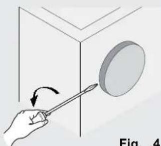
2) Unplug the stove from the power socket.
3) Unscrew the protection cap from thermostat with manual reset, located at the rear of the stove.
4) Press the button on the thermostat to reset the stove, Fig.12.1.
5) Perform the standard procedure, "Reset alarms", as described above.
If the alarm persists, check whether the stove or the flue require maintenance.


f the alarm occurs twice consecutively, immediately contact a Palazzetti service centre.
If the external thermostat is being used and an alarm is activated, the stove can only be started again from the control panel.

Fig. .1
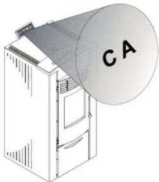
13 REMOTE CONTROL
The remote control is supplied as standard on some stoves only.
Operation of the remote control depends on the control panel settings.
The device is an infrared remote control, and therefore needs to be aimed at the receiver on the control panel (Fig=13=1% or at the antenna fitted at the rear of the stove, depending on the model of stove.
The remote control can be used to perform the following operations on the stove:
natural_image
Illustration of a server unit with a large cylindrical device labeled 'CA' (no text or symbols on the device itself)
Fig. .1
| FUNCTION BUTTONS DESCRIPTION AUDIBLE SIGNAL | |
| START |  | press both buttons together to start the stove | |
| SWITCH OFF |  | press both buttons together to switch the stove off | |
| INCREASE POWER |  | press button 1 to increase stove output by one power level | one beep* |
| DECREASE POWER |  | press button 2 to decrease stove output by one power level | one beep* |
| INCREASE FAN SPEED |  | press button 3 to increase fan speed by one level | one beep* |
| DECREASE FAN SPEED |  | press button 4 to decrease fan speed by one level | one beep* |
* when automatic speed is selected and power is managed automatically, three beeps will be emitted.
Whenever a button is pressed, the LED on the remote control flashes=
14 AIR DUCTS
(ONLY FOR DUCTED MODELS OR PROVIDED WITH DUCTING KIT)
Ducted Ecofire stoves or fitted with ducting kit can be configured to deviate the hot air produced to two different outlets.
One is for heating the room where the stove is installed, Fig.14.1 (A) through the front or top grills (according to the model). The other is used to heat other rooms away from the stove, Fig.14.1 (B), through a system of air ducts.
To deviate the flow of hot air (completely or partially% from one outlet to the other, use the special tool supplied with the stove and adjust the control placed between the front grills.

Some models of stove are already fitted with a lever to deviate the hot air on the stove itself (see the "PRODUCT BOOKLET" enclosed).
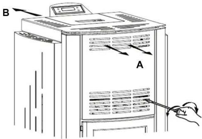
Fig..1
15 MAINTENANCE
15.1 SAFETY PRECAUTIONS
Before performing any maintenance operations, adopt the following precautions:
- Make sure that all the parts of the stove have cooled down.
- Make sure that the ash is completely extinguished.
- Use the personal protective equipment specified by directive 89/391/EEC.
- Make sure that the main power switch is off.
- Make sure that the power supply cannot be reconnected accidentally. Unplug the cord from the socket on the wall.
- Always use suitable tools for maintenance.
- Once maintenance or repairs have been completed, before operating the stove again, restore all protection features and reactivate all safety devices.
A suitable ash vacuum cleaner (canister) makes it simpler to clean the ash.
15.2 STOVE CLEANING FUNCTION
This function cleans the stove while preventing ash from spreading in the room.
During this operation the flue gas fan operates at maximum speed, thus preventing ash from leaving the firebox.
! It can only be activated when the stove has cooled down completely.
Press the OFF button for 2 seconds.
The flue gas fan will start at maximum speed.
At the end it will switch off automatically.
To stop the operation manually, press the OFF button.
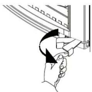
15.3 ROUTINE USER MAINTENANCE
15.3.1 Cleaning the inside of the fireboJ
The stove requires simple yet frequent and thorough cleaning in order to guarantee efficient and correct operation at all times.
Clean the stove only when it's off and has cooled down.
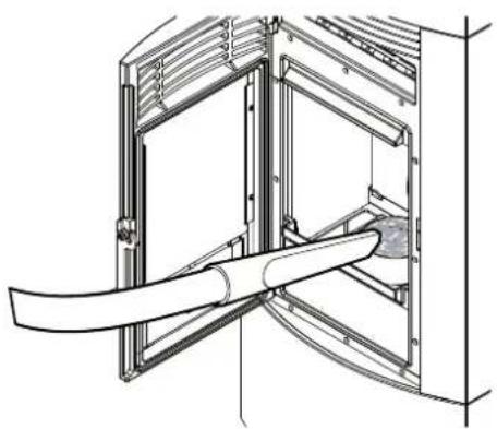
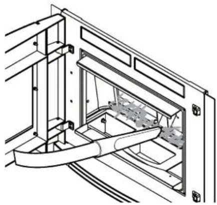
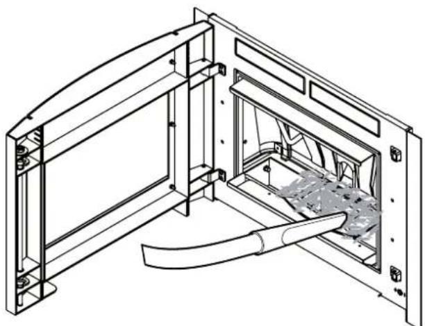
Use the handle or lever (according to the model of stove) to open the firebox door (Fig.15.1).
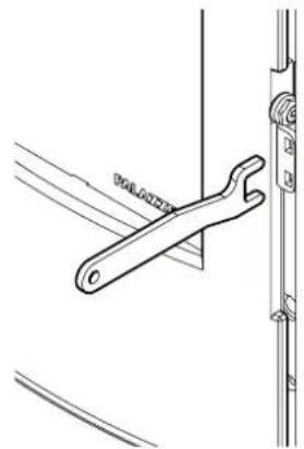
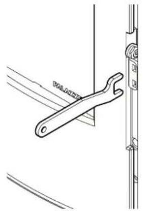
Some models of stove come with a separate handle for opening the door. Take the handle from the ash bin housing, place it in the holes on the door hinge and lever the mechanism to open the door (Fig.15.2).
15.3.2 Daily cleaning
Remove the ash that has accumulated inside the firebox (Fig.15.3).
This has the purpose of ensuring free flow of combustion air through the holes in the BURN POT.
natural_image
Illustration of a hand holding a device with an arrow indicating rotation (no text or symbols)


natural_image
Mechanical diagram showing a lever mechanism with motion arrows (no text or symbols)
Fig.15.1
natural_image
Technical line drawing of a wrench tool inserted into a bracket (no text or symbols)
Fig.15.2

natural_image
Technical line drawing of a mechanical assembly with a curved pipe inserted into a housing (no text or symbols)
natural_image
Technical line drawing of a mechanical assembly with internal components and a handle (no text or symbols)
Fig.15.3
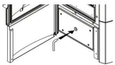
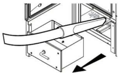
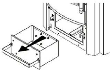
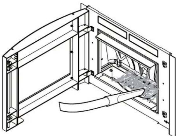
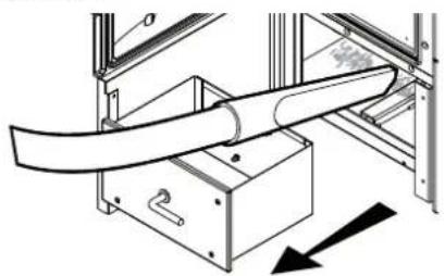
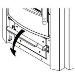
15.3.3 Cleaning the ash bin
(FOR MODELS FITTED WITH ASH BIN)
The ash bin should be cleaned every week or whenever necessary.
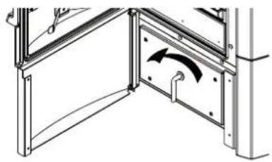
To access the ash bin, open the ash bin door and remove the bin (Fig.15.4) using the tool provided. Empty the bin. Vacuum any residual ash from the compartment that houses the ash bin. Reposition and close the ash bin. Close the doors. Some models are equipped with a handle (Fig.15.5).
natural_image
Technical diagram of a structural joint or bracket assembly (no text or symbols visible)

natural_image
Technical diagram of a structural frame with an arrow indicating rotational motion (no text or symbols present)
natural_image
Technical diagram of a mechanical assembly with a curved pipe and directional arrow (no text or symbols)
Fig.15.4

natural_image
Technical diagram of a door frame with a curved handle and arrow indicating rotation (no text or symbols)
natural_image
Technical line drawing showing a door frame with an open drawer and a black arrow indicating direction (no text or symbols)

natural_image
Technical line drawing of a structural frame with curved elements inside, labeled Fig. 15.6 and Fig. 15.5 (no text or symbols on the diagram itself)
Fig.15.6 Fig.15.5
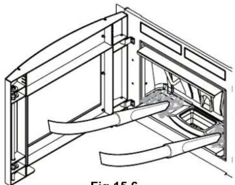
15.3.4 Cleaning the ash compartment
(FOR MODELS FITTED WITH ASH COMPARTMENT)
The ash compartment should be cleaned every week or whenever necessary.
Open the firebox door and use a special ash vacuum cleaner to remove the ash accumulated in the ash compartment next to the burn pot (Fig.15.6).
15.3.5 Cleaning the glass
This is done using a damp cloth or moistened paper passed through the ash. Rub until the glass is clean. Detergents suitable for cleaning kitchen ovens can also be used. Never clean the glass while the stove is operating and never use abrasive sponges. Do not wet the door gasket as this may be damaged.
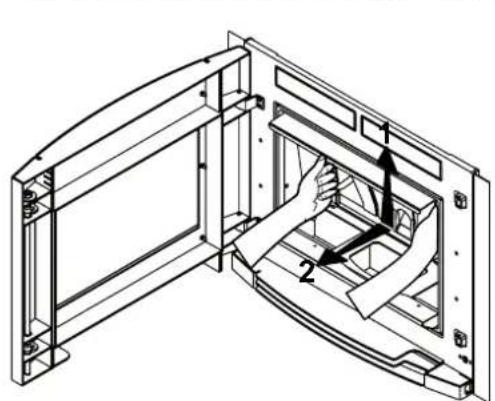
15.3.6 Cleaning the heat exchange compartment
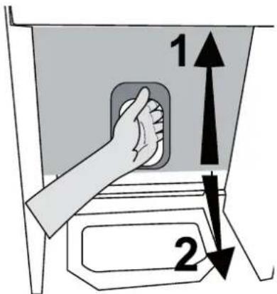
Twice every season the heat exchange compartment must be cleaned completely by removing the cast-iron back plate when cold. To remove the back plate, after having taken out the cast-iron burn pot, proceed as follows:
1) lift the cast-iron plate so that it's released from the special catches at the bottom (some models have handles to simplify removal, Fig.15.7 A);
2) tilt the bottom of the cast-iron plate towards the door and remove it completely. (Fig.15.7 A - B);
3) vacuum up any residual ash or soot that may have accumulated on the wall behind the back plate (Fig.15.8).
natural_image
Technical line drawing of a mechanical assembly with no visible text or symbols
Fig.15.7 A


natural_image
Technical line drawing of a mechanical assembly with internal components and mounting brackets (no text or symbols)
Fig.15.8 Fig.15.7 B
The presence of condensate indicates infiltration of water, excessive flue gas cooling or the use of poor quality pellets. The possible cause must be identified so as to restore correct operation of the appliance
After cleaning, carefully reposition all the parts that had been removed.
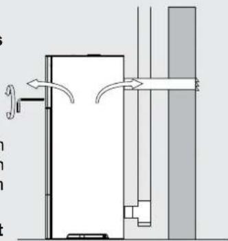
15.3.7 Cleaning the flue
This should be performed at least twice a year, at the start of and half-way through winter, and in any case whenever necessary (Fig.15.9). If there are horizontal sections, check for and remove any accumulated ash and soot before these block the flow of flue gas.
If not cleaned correctly, the stove may not operate properly, with problems including:
- poor combustion;
- blackening of the glass;
- blockage of the burn pot by ash and pellets;
- accumulated ash and excessive fouling of the heat exchanger, with a consequent decline in efficiency.
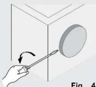
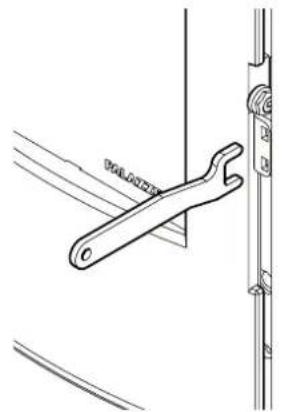
15.3.8 Adjusting the handle
(ONLY FOR MODELS FITTED WITH VERTICAL)
The door handle is adjusted in factory to ensure tightness when closing the door.
After a few weeks' operation the gaskets tend to settle and consequently the handle may need to be adjusted to make sure the door closes perfectly.
Proceed as follows (Fig.15.10):
- loosen the fastening screw (A) (2 mm Allen key).
- turn the rotation pin (C) (using a 15 mm spanner) until compensating for the play following settling of the gasket.
- Once the pin is correctly adjusted, tighten the screw again (A).
- The screw (B) can be turned (3.5 mm Allen key) to adjust handle tension, making rotation around the pin tighter or looser. (This adjustment is performed after having loosened the screw "A").
15.3.9 Cleaning the outside of the stove
The outside of the stove must only be cleaned using a dry, non-abrasive cloth.
! Do not use detergents and never clean when the stove is hot.

natural_image
Technical diagram of a vertical pipe system with a support structure and directional arrows (no text or labels)
Fig.15.9
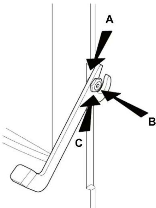
Fig.15.10
The ECOFIRE stove is a solid fuel fired heater and as such requires annual maintenance to be performed by a Palazzetti Authorised Service Centre once a year, preferably at the start of the season.
The purpose of such maintenance is to ensure all the components are in perfect working order.
If the control panel shows the message SPECIAL MAINTENANCE, immediately contact the Service Centre to have special maintenance performed on the stove.
Whenever the stove is started a long beep will be emitted and the message SPECIAL MAINTENANCE will be flash= This will be repeated until special maintenance has been completed=
It's recommended to stipulate an annual product maintenance contract with the Authorised Service Centre.
INSPECTION AND/OR MAINTENANCE PLAN
| WHENEVER STARTED | WEEKLY | 1 MONTH | 6 MONTHS 1 YEAR |
| Burn pot X | | | | |
| Ash bin/Compartment X | | | | |
| Glass X | | | | |
| Heat exchanger X | | | | |
| Ignition heater socket X | | | | |
| Flue gas manifold X | | | | |
| Door and burn pot gaskets* X | | | | |
| Flue* X | | | | |
| Fans* | | | | |
16 DECOMMISSIONING AND DISPOSAL
Decommissioning and disposal of the stove are the exclusive responsibility of the owner, who must act in
accordance with the laws in force in the country where the stove is installed with regards to safety and environmental protection.
The stove may also be dismantled and disposed of by companies authorised to recover and dispose of the materials in question.

natural_image
Four 3D white figures holding red envelopes and tools, no text or symbols present

INSTRUCTION: always observe the standards in force in the country where the stove is decommissioned as regards disposal of the materials and the waste disposal report where required.

IMPORTANT: All dismantling operations for decommissioning the stove must be performed when the stove is off and disconnected from the power supply.
- remove all electrical equipment;
- separate the batteries fitted on the electronic boards;
have the structure of the stove scrapped by an authorised company;
! IMPORTANT: Dumping the stove in accessible areas represents a serious hazard to people and animals. Liability for any harm caused to people or animals always lies with the owner.
When decommissioning the stove the ce mark, this manual and other documents relating to this stove must be destroyed.
ZUSAMMENFASSUNG FÜR QUALIFIKATION

UTENTE
natural_image
Five 3D human figures in various poses: walking, carrying a red ribbon, wrench, and wheel switch (no text or symbols)
1.3 ZWECK UND INHALT DES HANDBUCHS
natural_image
Pile of brown fuel cells in a plastic bag, with scattered grains on the ground (no text or symbols visible)
Fig. 3.1
Fig. 5.3

Fig. 5.4
natural_image
Architectural cross-section diagram showing wall and brick wall components with directional arrows (no text or labels)
Fig. 5.6

Fig. 5.7
Fig. 5.9
6 INSTALLATION

natural_image
Three 3D white figures with red tools, one carrying a sack and the other holding a wrench (no text or symbols visible)
natural_image
Diagram of a hand holding a plug with a circular component inserted into a wall socket (no text or symbols)
Fig. 6.2
natural_image
Diagram of a door mechanism with directional arrows indicating movement, no text or symbols present
Fig. .3
natural_image
Hand holding a tool interacting with a circular object, labeled Fig. 4 (no text or symbols on the object itself)
Fig. .4
natural_image
3D figure holding a red wrench, no text or symbols present
natural_image
Diagram showing a wall-mounted switch and pipe connection, with circular elements arranged in a grid pattern (no text or symbols)
Fig. .1
natural_image
Illustration of a server unit with a large cylindrical device labeled 'CA' (no text or symbols on the device itself)
Fig. .1
natural_image
Illustration of a hand holding a device with an arrow indicating rotation (no text or symbols)


natural_image
Diagram of a mechanical lever mechanism with motion arrows (no text or symbols)
Fig.15.1
natural_image
Technical line drawing of a wrench tool inserted into a bracket (no text or symbols)
Fig.15.2

natural_image
Technical line drawing of a mechanical assembly with a curved pipe inserted into a housing (no text or symbols)
natural_image
Technical line drawing of a mechanical assembly with internal components and mounting brackets (no text or symbols)
Fig.15.3
(MODELLE MIT ASCHEKASTEN)
natural_image
Technical diagram of a structural joint or bracket assembly (no text or symbols visible)

natural_image
Technical diagram of a structural frame with an arrow indicating rotational motion (no text or symbols present)
natural_image
Technical diagram of a mechanical assembly with a curved component and directional arrow (no text or symbols)
Fig.15.4
natural_image
Technical diagram of a mechanical assembly with a curved component and directional arrow (no text or symbols)

natural_image
Technical line drawing of a mechanical assembly with an open box and internal components (no text or symbols)
Fig.15.5
natural_image
Technical line drawing of a structural frame with curved elements inside, labeled Fig. 15.6 (no text or symbols on the diagram itself)
Fig.15.6
natural_image
Technical line drawing of a mechanical assembly with no visible text or symbols
Fig.15.7 A


natural_image
Technical line drawing of a mechanical assembly with no visible text or symbols
Fig.15.8 Fig.15.7 B
natural_image
Technical diagram of a vertical pipe system with a support structure and directional arrows (no text or labels)
Fig.15.9
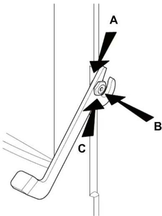
Fig.15.10
natural_image
Four 3D human figures in action poses, one holding a red tool, no text or symbols present
4 MANUTENTION ET TRANSPORT
4.1 ENLEVEMENT DE LA PALETTE DE TRANSPORT 93
5 PREPARATION DU LIEU D'INSTALLATION
5.1 CONSIDERATIONS GENERALES
5.2 MESURES POUR LA SECURITE 94
5.3 LIEU D'INSTALLATION DU POELE 94
5.4 AIR COMBURANT 95
5.5 ÉVACUATION DE LA FUMÉE 96
6 INSTALLATION 98
6.1 MISE A NIVEAU DU POELE 98
6.2 BRANCHEMENTS 98
7 DESCRIPTION DU POELE 100
7.1 PANNEAU DE COMMANDE 100
7.2 PARAMÈTRES DE FONCTIONNEMENT 100
7.3 ACCES AUX MENUS 101
8 OPERATIONS PRELIMINAIRES 102
8.1 CHARGEMENT DES PELLETS 102
8.2 ALIMENTATION ELECTRIQUE 102
8.3 PARAMETRAGES PRELIMINAIRES 102
9 UTILISATION DU POELE 103
9.1 ALLUMAGE 103
9.2 MODIFICATION DES PARAMETRES 103
9.3 EXTINCTION 103
10 FONCTIONS DISPONIBLES 104
10.1 FONCTION TIMER 104
10.2 FONCTION STAND-BY 106
10.3 FONCTION ANTIGEL 106
10.4 FONCTION "ECONOMY" 106
10.5 RALLUMAGE APRES UNE COUPURE DE COURANT
106
10.6 LECTURE HEURES DE FONCTIONNEMENT 106
natural_image
Five 3D human figures in various poses: walking, carrying bags, wrench, tool, and shopping cart (no text or symbols)
natural_image
A bag filled with small brown granular material, placed on a white surface with scattered grains nearby (no visible text or symbols)
Fig. 3.1
4 MANUTENTION ET TRANSPORT
A% Cloison adjacente=
B) Cloison arrière.
Fig. 5.3

Fig. 5.4
natural_image
Architectural cross-section diagram showing wall and brick wall components with directional arrows (no text or labels)
Fig. 5.6

Fig. 5.7
Fig. 5.9
6 INSTALLATION
natural_image
Three 3D white figures with red tools, one carrying a sack and the other holding a wrench (no text or symbols visible)
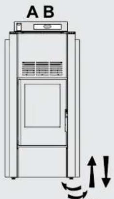
Fig. .1
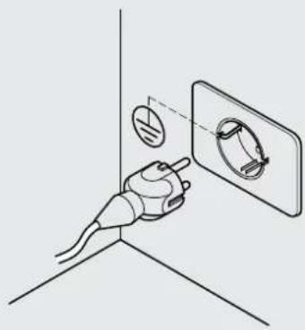
natural_image
Diagram of a hand holding a plug with a circular component inserted into a wall, no text or symbols present
Fig. 6.2
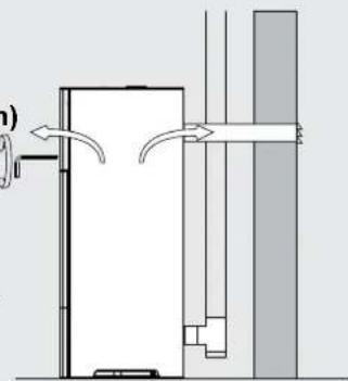
natural_image
Diagram of a door mechanism with arrows indicating flow direction (no text or symbols)
Fig. .3
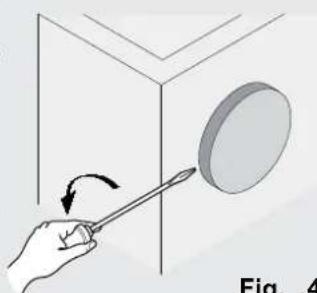
natural_image
Hand holding a tool interacting with a circular object inside a 3D cube (no text or symbols visible)
Fig. .4
EMPLOI & ENTRETIEN

natural_image
3D white figure holding a red folder, no text or symbols visible

natural_image
3D illustration of a white figure holding red wrenches (no text or symbols)
7 DESCRIPTION DU POELE
natural_image
Diagram showing a wall-mounted switch and pipe connection, with circular elements arranged in a grid pattern (no text or symbols)
Fig. .1
10 FONCTIONS DISPONIBLES

10.1 FONCTION TIMER
10.8 FONCTIONNEMENT AVEC THERMOSTAT AMBIANT
natural_image
Illustration of a server unit with a large cylindrical device labeled 'CA' (no text or symbols on the device itself)
Fig. .1
natural_image
Illustration of a hand holding a device with an arrow indicating rotation (no text or symbols)
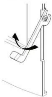
natural_image
Diagram of a mechanical lever mechanism with motion arrows (no text or symbols)
Fig.15.1

natural_image
Technical line drawing of a wrench gripping a vertical pipe (no text or symbols)
Fig.15.2

natural_image
Technical line drawing of a mechanical assembly with a curved pipe inserted into a housing (no text or symbols)
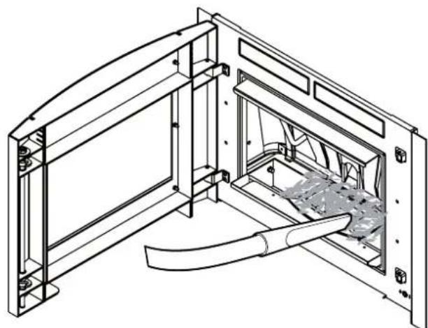
natural_image
Technical line drawing of a mechanical assembly with internal components and mounting brackets (no text or symbols)
Fig.15.3
natural_image
Technical diagram of a structural joint or bracket assembly (no text or symbols visible)

natural_image
Technical line drawing of a structural frame with an arrow indicating direction (no text or symbols)

natural_image
Technical diagram of a mechanical assembly with a curved pipe and directional arrow (no text or symbols)
Fig.15.4
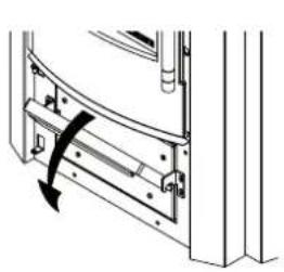
natural_image
Mechanical assembly diagram showing a curved component with a rotation arrow (no text or symbols)

natural_image
Technical line drawing showing a door frame with an open drawer and a black arrow indicating direction (no text or symbols)
Fig.15.5

natural_image
Technical line drawing of a structural frame with curved elements inside, labeled Fig. 15.6 (no text or symbols on the diagram itself)
Fig.15.6
natural_image
Technical line drawing of a mechanical assembly with no visible text or symbols
Fig.15.7 A


natural_image
Technical line drawing of a mechanical assembly with no visible text or symbols
Fig.15.8 Fig.15.7 B
natural_image
Technical line drawing of a mechanical or industrial device with a vertical pipe and support structure (no text or symbols)
Fig.15.9
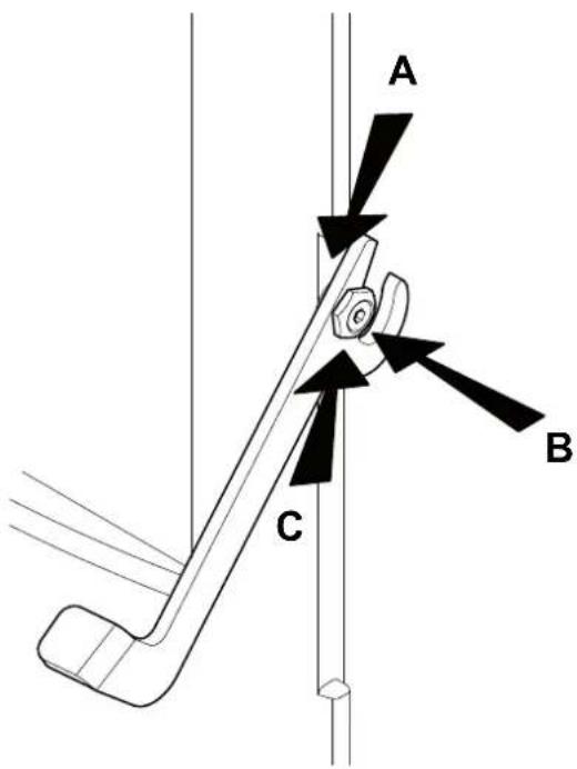
Fig.15.10
natural_image
Four 3D human figures in action poses, one holding a red tool, others handling tools (no text or symbols)
16 DESOSSEMENT ET MISE AU REBUT
natural_image
Five 3D human figures in various poses: walking, carrying a red bag, using wrench and gear, and pulling a cart (no text or symbols)
natural_image
A bag of brown fuelwood pellets with a label, spilling out seeds on a white surface (no readable text or symbols in the image)
Fig. 3.1
TRANSPORTE
Fig. 5.3

Fig. 5.4
ESTUFAS DE LA SERIE "ERMETICA"
natural_image
Architectural cross-section diagram showing wall and brick wall components with directional arrows (no text or labels)
Fig. 5.6

Fig. 5.7
Fig. 5.9
6 INSTALACIÓN
natural_image
Three 3D white figures with red tools, one carrying a sack and the other holding a wrench (no text or symbols visible)
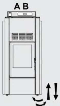
Fig. .1
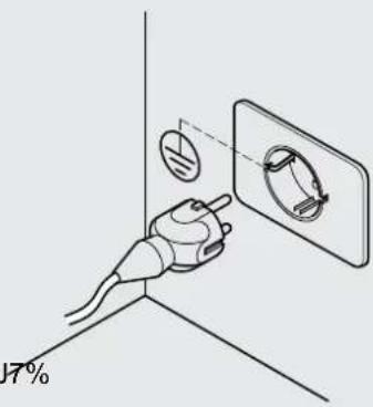
Fig. 6.2
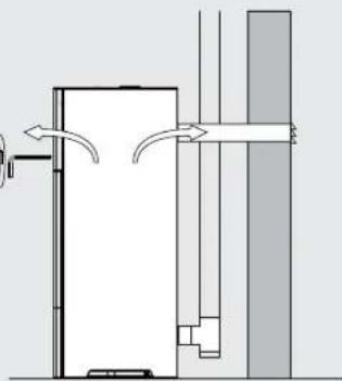
natural_image
Pure architectural diagram showing airflow or ventilation between two vertical walls (no text or symbols)
Fig. .3

natural_image
Hand holding a tool interacting with a circular object, labeled 'Fig. .4' (no text or symbols on the object itself)
Fig. .4
USO Y MANTENIMIENTO

natural_image
3D figure holding a red folder, no text or symbols visible

natural_image
3D illustration of a white figure holding red wrenches (no text or symbols)
natural_image
Diagram showing a wall-mounted switch and pipe connection, with circular elements arranged in a grid pattern (no text or symbols)
Fig. .1
11.3 MENÚ SET ESTUFA
natural_image
Illustration of a server unit with a large cylindrical device labeled 'CA' (no text or symbols on the device itself)
Fig. .1
natural_image
Illustration of a hand holding a tool with an arrow indicating rotation (no text or symbols)

natural_image
Diagram of a mechanical lever mechanism with motion arrows (no text or symbols)
Fig.15.1

natural_image
Technical line drawing of a wrench gripping a vertical rail, no text or symbols present
Fig.15.2

natural_image
Technical line drawing of a mechanical assembly with a curved pipe inserted into a housing (no text or symbols)
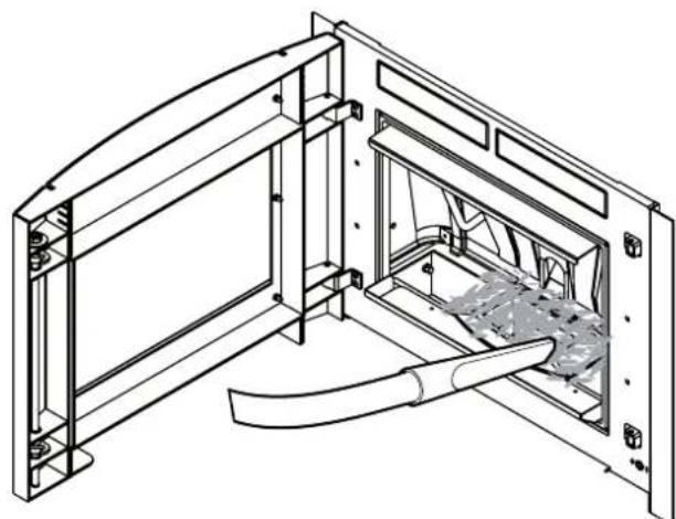
natural_image
Technical line drawing of a mechanical assembly with internal components and mounting brackets (no text or symbols)
Fig.15.3
natural_image
Technical diagram of a structural joint or bracket assembly (no text or symbols visible)
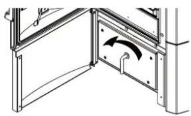
natural_image
Technical line drawing of a structural frame with an arrow indicating direction (no text or symbols)

natural_image
Technical diagram of a mechanical assembly with a curved pipe and directional arrow (no text or symbols)
Fig.15.4
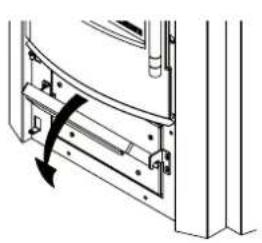
natural_image
Technical diagram of a door frame with a curved handle and arrow indicating rotation (no text or symbols)

natural_image
Technical line drawing of a mechanical assembly with an open box and internal components (no text or symbols)

natural_image
Technical line drawing of a structural frame with curved elements, no text or symbols present
Fig.15.6 Fig.15.5
natural_image
Technical line drawing of a mechanical assembly with no visible text or symbols
Fig.15.7 A


natural_image
Technical line drawing of a mechanical assembly with internal components and mounting brackets (no text or symbols)
Fig.15.8 Fig.15.7 B
natural_image
Technical diagram of a vertical pipe system with a support structure and directional arrows (no text or labels)
Fig.15.9

Fig.15.10
Palazzetti accepts no liability for any mistakes in this handbook and is free to modify the features of its products without prior notice.