
Electra 6134 - Faucet Oras - Free user manual and instructions
Find the device manual for free Electra 6134 Oras in PDF.

| Product type | Electronic faucet with infrared detection |
| Brand | Oras |
| Model | Electra 6134 |
| Power supply | Low voltage 12 V via external transformer (model 6134) |
| Mains voltage | 230 V (for transformer, installation by electrician for models 6104/6105) |
| Detection mode | Infrared cell |
| Operation | Automatic opening of solenoid valve when hands pass |
| Safety shut-off | Automatic shut-off after 2 minutes if cell is obscured |
| Beam length adjustment | Via button (quick press) and memory: place an obstacle at the desired distance |
| Flow delay adjustment | Via ORAS terminal (version 2.4 or higher); preset to 1 second |
| Field of use | Hospitals, clinics, public toilets, restaurants, nurseries, schools, retirement homes, food industries |
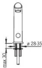
| Mounting hole diameter | Minimum 32 mm |
| Water connection | Hot water on left, cold water on right; integrated check valves |
| Filter maintenance | Rinse under running water if flow decreases |
| Cleaning the faucet | Non-acidic and non-abrasive products; do not use high-pressure cleaner |
| Frost protection | Drain the faucet and solenoid valve if there is a risk of frost |
| Anti-vandalism safety | Automatic shut-off if cell obscured more than 2 minutes (adhesive tape, chewing gum, etc.) |
| Number of manual pages | 52 |
| Languages available in the manual | FR, DA, DE, EN, ES, ET, FI, IT, NL, NO, PL, RU, SV |
Frequently Asked Questions - Electra 6134 Oras
User questions about Electra 6134 Oras
0 question about this device. Answer the ones you know or ask your own.
Ask a new question about this device
Download the instructions for your Faucet in PDF format for free! Find your manual Electra 6134 - Oras and take your electronic device back in hand. On this page are published all the documents necessary for the use of your device. Electra 6134 by Oras.
USER MANUAL Electra 6134 Oras
Installation and Maintenance Guide
Oras Electra
Oras Electra
6104, 6134, 6105, 6135
DE Deutsch. 9
GB English 12
DK Dansk 15
ES Espanol 18
EE Eesti 21
FISuomi 24
NLNederlands 27
FR Francais 30
Italiano 33
NO Norsk 36
PL Polski 39
RU Pycckn 42
SE Svenska 45
6104
EN 15091
I (ISO 3822)
50 - 1000 kPa
0.11 l/s (300 kPa) (with flow controller)
170 kPa (0.1 l/s)
max. +80^ C


STF VTT-RTH-00112-11
Sintef Nr. 0312
CE (EMC 89/336/EEC)
6134
EN 15091
I (ISO 3822)
50 - 1000 kPa
0.11 l/s (300 kPa) (with flow controller)
170 kPa (0.1 l/s)
max. +80^ C

STF VTT-RTH-00112-11
VA 1.42/18178
CE (EMC 89/336/EEC)
6105
EN 15091
I (ISO 3822)
50-1000kPa
0.11 l/s (300 kPa) (with flow controller)
220 kPa (0.1 l/s)
max. +80^ C


STF VTT-RTH-00112-11
Sintef Nr. 0312
CE(EMC89/336/EEC)
Technical data
| CZ Technicky data DE Technische Daten DK Tekniske data | EE Tehnilised andmed ES Datos先进技术 FI Tekniset tiedot | FR Données techniques IT Dati technici LT Techninai duomenys | LV Tehniskie dati NL Technische gevevens NO Teknisk informasjon | PL Dane technicznce RO Date tehnice RU Technique udaje | SE Teknisk information SK Technické udaje |
| GB CZ DE DK EE ES FI FR IT LT LV NL NO PL RO RU SE SK | Electrical Connection Napájeci napěti Elektr. Anschluß Elektrisk tilslutting Elektriliades Instalación electrónica Sähköllitànta Connexión electrique Collegamento eletrico Maitinimo saltinis Elektrobarošana Electrische aansluiting Elektrisk tlikobling Podlaczenia elektryczne Conexiune electricà Зелекtronitàanie | Protection class Tifida bezpečnosti Sicherheitsklasse Beskyttelsesklasse Kaitseklass Grado de protección Sujoausluokka Norme de sécurité Protezione classe Saugumo klase Aizsardzibas klase Veiligheidsklasse Tetthetsklasse Klasa bezpiecieżstwa Clasa de proteçèie Стенихтоцпь | Recognition range Rozlišovací rozsah Sensorreichweite Sensor obrade Toimimiskaugus Alcance del sensor Tunnistusalue Longueur du faisceau Raggio d'azione del sensore Atpázinalo atstumas Atpážíanas diapazpns Sensorbereik Folsomhetsomráde Zasięd dzialania Raza de sesizare Pacstórahye onoэнавиу Kānslighetsomráde Rozlišovacia vzdialenost | Afterflow period Dodatečný průtok Nachlaufzeit Efterllobetid Järelvool Tiempo de retardo Jälkivirtaama Temporisation de débit Scorrimento posteriorie Tekéjmo trukmè po prausimosi Skalošanas periods Nalooptijd Etterrenningsid Opóznienie zamknęcia Interval Perioadà de curgere remanentà Опалackиевиа Efterflödestid Čas dodatočného prietoku | Max. flow period Max. doba průtoku Max. Fließdauer Max. lobotid Maksimalne vee vooluajpa pikkus Periodemaximum de flujo Max. virtausika Durée maximum d'écolement Scorrimento mass. Maksimali svres tekéjmo trukmè Maksimalais plüssmas periodis Max. looptijd Funksjonstid Max czas przyplywu Perioadà max. de curgere Mák. břem na podaeni bodi |
| 6104 6105 6134 | 230 VAC 230 VAC 230 VAC/12 VAC | IP 67 IP 67 IP 67/transformer IP 40 | 0-40 cm 0-40 cm 0-40 cm | 1 s (0-255 s) 1 s (0-255 s) 1 s (0-255 s) | 2 min 2 min 2 min |
1
2

6104,6134
Oras Data Terminal
6105
6104, 6105, 6134
5
Installation and Maintenance Guide
GB
General
The Electra Installation and Maintenance Guide introduces the operation, installation, maintenance and use of the Oras Electra lavatory faucet. Please read the instructions carefully prior to installation and save them for reference where servicing may be needed. If any fault or malfunction occurs in the faucet, please seek the best possible advice at an expert HVAC store.
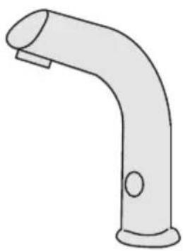
Function
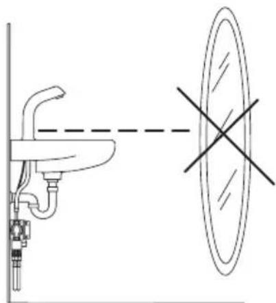
Touchless Electra faucets are turned on and shut off by a solenoid valve that is actuated by a photocell. When the hands are held under the faucet, the solenoid valve opens and water starts to flow. When the hands are removed, the faucet shuts automatically.
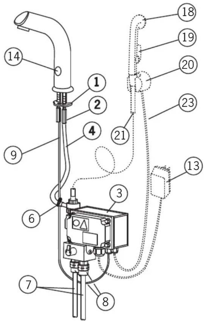
Handshower (see figure 1)
On models with handshower (6105), water begins to flow from the spout when the showerhead (18) is removed from its wall bracket (20). If the button on the showerhead is pressed in, water begins to flow from the showerhead and water flow from the spout stops.
Applications
Touchless Electra faucets are intended for use in areas that require a high standard of hygiene, e.g. hospitals, doctors' offices, food processing plants etc. Electra faucets are also suitable for use where there is a possibility that a faucet can be left running, e.g. public toilets, restaurants, schools etc.
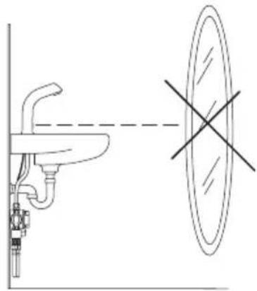
The wash-basin to which the Electra faucet is to be fixed may not be of the kind that can be plugged.
To clean the faucet
When cleaning the surface of the faucet, use neutral liquid detergents only. Do not use any scrubbing or corrosive cleaning agents!
WARNING: Do not clean the appliance with a high pressure washer.
Risk of freezing
When installing the faucet in a place where the temperature may fall below freezing, the entire system must be drained of water to prevent bursting in freezing weather.
-
Shut off the water supply.
-
Disconnect all flexible hoses and make certain that all parts and hoses are drained of water.
Protection against vandalism
If the eye of the photocell is continuously covered for over 2 minutes, or if the showerhead is used for over 2 minutes (i.e. no contact with the sensor in the wall bracket) the faucet shuts automatically. To regain normal operation, remove the blockage (e.g. chewing gum, tape) from the photocell, or replace the showerhead in the wall bracket.
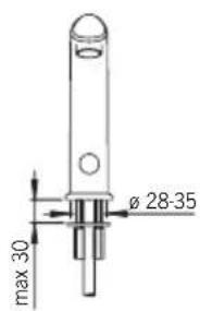
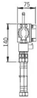
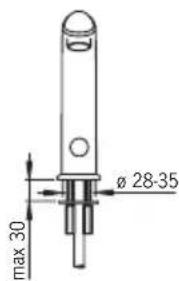
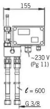
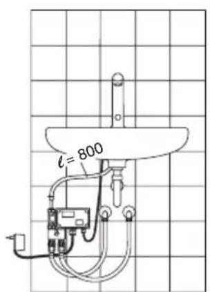
Installation (see Figure 1, 3 or 4)
- Mount the no-touch faucet on the wash-basin (min. 028-35 mm). Ensure that the seal between the faucet and the wash-basin is correctly installed.
- Slip the fixing washer (1) and stud nuts (2) into position and tighten with a screwdriver or 9mm adjustable wrench.
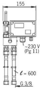
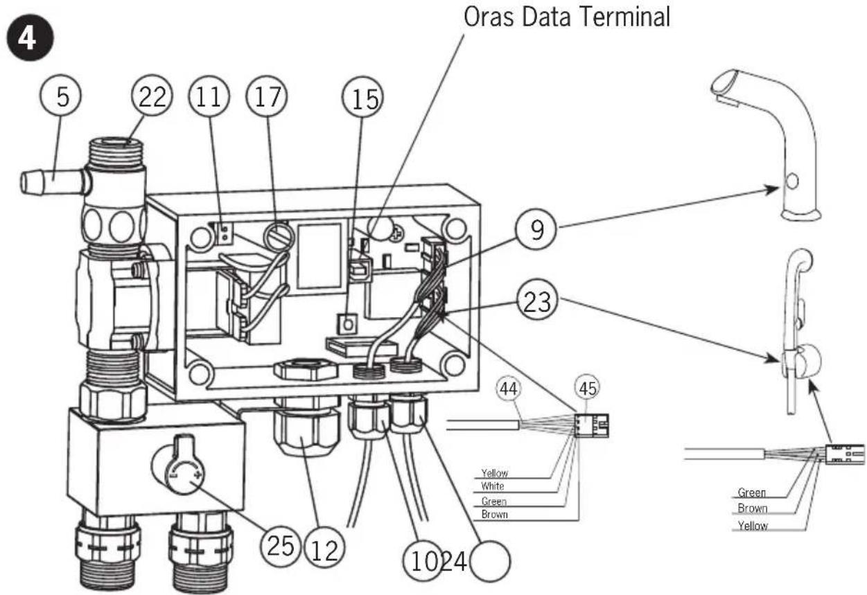
- Remove the control-box cover.
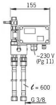
- Using the four screws supplied, mount the control box (3) on to a suitable place in the cabinet or on the wall below the basin, in a position that permits easy access for maintenance.
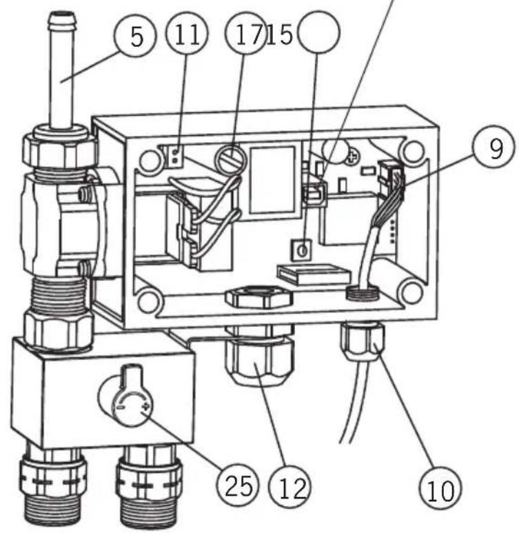
- Cut the hose (4) to the proper length and attach it to the connector (5) on the controlbox.
- Secure the hose with a hose clamp (6).
- On models with handshower (6105), attach the handshowerhose (21) to the control-box nipple (22).
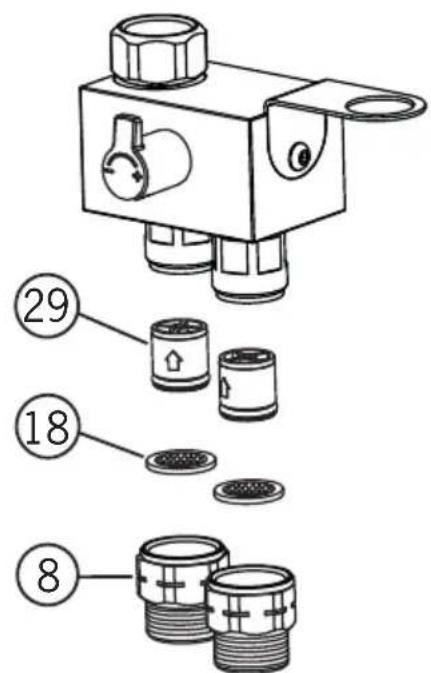
Connecting the Water-Supply Hoses
- Attach one end of each of the flexible water-supply hoses (7) to the control-box attachment nipples (8). The nipples contain non-return valves (29).
- Connect hot water to the left-hand water-supply hose and cold water to the right-hand hose.
Electrical Connections
- Install the sensor wire (9) to the control box and tighten the cable gland with the nut (10)
- On models with handshower (6105), install the sensor wire (23) that comes from the wall bracket (20) to the control box and tighten the cable gland with the nut (24).
6104 and 6105:
Connect 230V mains voltage to the control box as follows:
- Remove the connector (11) e.g. by prying off with a small screwdriver.
- Make sure that the electric wires are not live and then attach them to the connector.
- Push the connector and wires back into the counterpart.
- Pull any loose wire through the cable gland and out of the control box.
- Tighten the cable gland (12) nut.
PLEASE NOTE!
The electrical installation of the 6104 and 6105 requires a qualified electrician, and must include a two-pole trip device with a circuit breaker of at least 3mm .
6134:
- Put the contact plug transformer (13) into a 230V wall socket.
- The control box operates at low voltage (12 V), so a plumber may also install and adjust the faucet.
PLEASE NOTE!
When connecting the mains voltage to the appliance, the solenoid valve will always be open for a moment.
- Turn on the water supply to the faucet.
- Check that the connections are watertight and that the faucet operates by placing your hand in front of the photocell (14).
- Replace the control-box cover.
- Stick the instruction label supplied in a place where it can be seen easily.
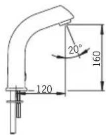
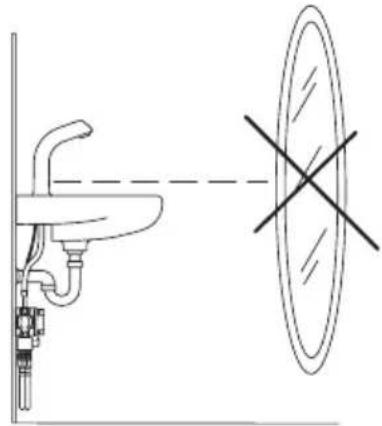
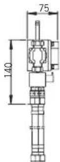
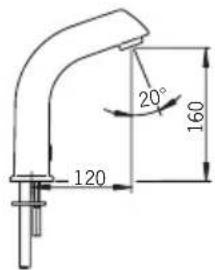
After-flow time and recognition range (see Figure 2)
After-flow time is the period of time between the moment the photocell ceases to be activated and the moment the water stops flowing. The recognition range is the greatest distance that an object can have from the photocell to activate it and open the faucet. The after-flow time and sensing range have been preset at the factory. If necessary, they can be adjusted as follows:
Recognition range
- Remove the control-box cover.
- Push the button (15).
- Position a piece of white paper (e.g. the installation instructions) vertically in front of the mixer, at the distance at which the photocell is intended to react (e.g. at the outer edge of the basin).
- Hold the paper at this distance. Water will start to flow after about 30 seconds.
Pull the paper away after the water flow has stopped!
- The recognition range is now set and stored.
- This information will not be lost from memory if there is a power failure.
- Should the distance prove unsatisfactory, simply readjust by changing the position of the piece of paper.
- Replace the control-box cover.
- The recognition range can also be adjusted using the Oras Data Terminal (v. 2.4 or later).
After-flow Time (factory-set to 1 second)
- After-flow time can be adjusted using the Oras Data Terminal (v. 2.4 or later).
Cleaning the Filter (see Figure 2)
If the water flow has decreased, this may be because the filter is clogged. Clean the filter as follows:
- Shut off the water supply to the faucet.
- Unscrew the strainer (18) from the valve housing.
Clean the strainer under running water.
Screw the strainer back.
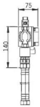
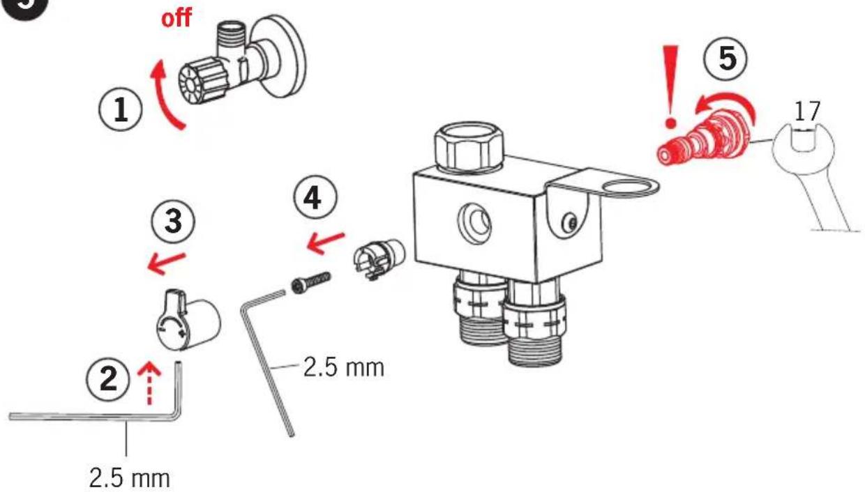
Changing the temperature regulator (see Figure 5)
Troubleshooting
Symptom Cause / Solution
Water flow from the outlet does - The sensing range is too low not stop, or stops after 2 minutes - Check that the photocell is clean - The solenoid valve is damaged Water flow is low and weak - Filter is clogged
No water comes out of the faucet - Check the water supply to the control box
- The solenoid valve is damaged
Power failure
The photocell is covered or damaged - 6105: the showerhead is not placed properly in its wall bracket
- Check the fuse (17) inside the control box:
6104 and 6105: 0.1 A
6134: 1A
Oras is a significant developer, manufacturer and marketer of sanitary fittings. Since its founding in 1945 the company has introduced high-quality design products featuring user-friendly technical solutions that contribute to savings of water and energy. As early as in the in the 1990s, Oras introduced the first touchless electronic faucets in the market.
Oras is owned by Oras Invest, a family company. In September 2013 Oras acquired Hansa Metallwerke AG, a German faucet manufacturer, with its subsidiaries, and together the companies form the new Oras Group. The head office of the Group is located in Rauma, Finland, and the company's factories are located in Rauma, Burglengenfeld (Germany), Kralovice (Czech Republic) and Olesno (Poland). The Group employs about 1400 people.
Det Norske Veritas Certification OY/AB certifies that the Quality Management System of Oras Oy in Rauma Finland, conforms to the ISO 9001, the Environmental Management System to the ISO 14001 standard and the Occupational Health and Safety System to the OHSAS 18001 standard. The certificates are valid for development, manufacture, marketing, sales and after sales services of faucets, accessories and valves.
The TUV CERT Certification Body of TUV NORD Zertifizierungs- und Umweltgutachter Gesellschaft mbH certifies that the Quality Management System of Oras Olesno Sp. z o.o. in Olesno Poland, conforms to the ISO 9001, the Environmental Management System to the ISO 14001 standard and the Occupational Health and Safety System to the OHSAS 18001 standard. The certificates are valid for manufacture, storage, marketing, sales and after sales services of faucets, valves and accessories.

ORAS GROUP
Isometsantie 2, P.O. Box 40
FI-26101 Rauma
Finland
Tel. +358 2 83 161
Fax +358 28316300
Info.Finland@oras.com

www.oras.com