
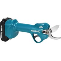
CC301D - Scissors MAKITA - Free user manual and instructions
Find the device manual for free CC301D MAKITA in PDF.

| Product type | Cordless scissors |
| Brand | Makita |
| Model | CC301D |
| Disc diameter | 85 mm |
| Max. disc thickness | 0.8 mm |
| Max. cutting depth (at 0°) | 25.5 mm |
| Max. cutting depth (at 45°) | 16.5 mm |
| No-load speed | 1 600 min⁻¹ |
| Rated voltage | 10.8 V - 12 V DC max. |
| Compatible battery | BL1015, BL1016, BL1020B, BL1021B, BL1040B, BL1041B |
| Overall length | 313 - 331 mm |
| Net weight (with battery) | 1.8 - 1.9 kg |
| Sound pressure level | 84 dB(A) |
| Sound power level | 95 dB(A) |
| Vibration (concrete cutting) | 2.5 m/s² or less |
| Application | Cutting glass and masonry materials |
| Water supply | Integrated, with reservoir |
| Bevel cutting | 0° to 45° |
| Safety | Protection guard, arbor lock, battery protection system |
| Maintenance | Clean ventilation slots, use Makita parts |
| Warranty | Refer to the manual |
Frequently Asked Questions - CC301D MAKITA
User questions about CC301D MAKITA
0 question about this device. Answer the ones you know or ask your own.
Ask a new question about this device
Download the instructions for your Scissors in PDF format for free! Find your manual CC301D - MAKITA and take your electronic device back in hand. On this page are published all the documents necessary for the use of your device. CC301D by MAKITA.
USER MANUAL CC301D MAKITA
| Model: CC301D | |||
| Diamond wheel diameter 85 mm | |||
| Max. wheel thickness 0.8 mm | |||
| Max. Cutting depth at 0° bevel 25 | .5 mm | ||
| at 45° bevel 16.5 mm | |||
| Rated speed 1,600 min | -1 | ||
| Rated voltage D.C. 10.8 V - 12 V max | |||
| Battery cartridge BL1015, BL1016, BL1020B, | BL1021B | BL1040B, BL1041B | |
| Overall length 313 mm 331 mm | |||
| Net weight 1.8 kg 1.9 kg | |||
Due to our continuing program of research and development, the specifications herein are subject to change without notice.
Specifications and battery cartridge may differ from country to country.
Weight, with battery cartridge, according to EPTA-Procedure 01/2003
Intended use
The tool is intended for cutting in glass and masonry materials with a diamond wheel and water.
Noise
The typical A-weighted noise level determined according to EN60745:
Sound pressure level (L_pA):84dB(A)
Sound power level (L_WA):95dB (A)
Uncertainty (K): 3 dB(A)

WARNING: Wear ear protection.
Vibration
The vibration total value (tri-axial vector sum) determined according to EN60745:
Work mode: concrete cutting
Vibration emission (a_h):2.5m / s^2 or less
Uncertainty (K): 1.5m / s^2
NOTE: The declared vibration emission value has been measured in accordance with the standard test method and may be used for comparing one tool with another.
NOTE: The declared vibration emission value may also be used in a preliminary assessment of exposure.
WARNING: The vibration emission during actual use of the power tool can differ from the declared emission value depending on the ways in which the tool is used.
WARNING: Be sure to identify safety measures to protect the operator that are based on an estimation of exposure in the actual conditions of use (taking account of all parts of the operating cycle such as the times when the tool is switched off and when it is running idle in addition to the trigger time).
EC Declaration of Conformity
For European countries only
The EC declaration of conformity is included as Annex A to this instruction manual.
SAFETYWARNINGS
General power tool safety warnings
WARNING: Read all safety warnings and all instructions. Failure to follow the warnings and instructions may result in electric shock, fire and/or serious injury.
Save all warnings and instructions for future reference.
The term "power tool" in the warnings refers to your mains-operated (corded) power tool or battery-operated (cordless) power tool.
Cordless cutter safety warnings
- The guard provided with the tool must be securely attached to the power tool and positioned for maximum safety, so the least amount of wheel is exposed towards the operator. Position yourself and bystanders away from the plane of the rotating wheel. The guard helps to protect operator from broken wheel fragments and accidental contact with wheel.
-
Use only diamond cut-off wheels for your power tool. Just because an accessory can be attached to your power tool, it does not assure safe operation.
-
The rated speed of the accessory must be at least equal to the maximum speed marked on the power tool. Accessories running faster than their rated speed can break and fly apart.
- Wheels must be used only for recommended applications. For example: do not grind with the side of cut-off wheel. Abrasive cut-off wheels are intended for peripheral grinding, side forces applied to these wheels may cause them to shatter.
- Always use undamaged wheel flanges that are of correct diameter for your selected wheel. Proper wheel flanges support the wheel thus reducing the possibility of wheel breakage.
- The outside diameter and the thickness of your accessory must be within the capacity rating of your power tool. Incorrectly sized accessories cannot be adequately guarded or controlled.
- The arbour size of wheels and flanges must properly fit the spindle of the power tool. Wheels and flanges with arbour holes that do not match the mounting hardware of the power tool will run out of balance, vibrate excessively and may cause loss of control.
- Do not use damaged wheels. Before each use, inspect the wheels for chips and cracks. If power tool or wheel is dropped, inspect for damage or install an undamaged wheel. After inspecting and installing the wheel, position yourself and bystanders away from the plane of the rotating wheel and run the power tool at maximum no load speed for one minute. Damaged wheels will normally break apart during this test time.
- Wear personal protective equipment. Depending on application, use face shield, safety goggles or safety glasses. As appropriate, wear dust mask, hearing protectors, gloves and shop apron capable of stopping small abrasive or workpiece fragments. The eye protection must be capable of stopping flying debris generated by various operations. The dust mask or respirator must be capable of filtrating particles generated by your operation. Prolonged exposure to high intensity noise may cause hearing loss.
- Keep bystanders a safe distance away from work area. Anyone entering the work area must wear personal protective equipment. Fragments of workpiece or of a broken wheel may fly away and cause injury beyond immediate area of operation.
- Hold the power tool by insulated gripping surfaces only, when performing an operation where the cutting accessory may contact hidden wiring. Cutting accessory contacting a "live" wire may make exposed metal parts of the power tool "live" and could give the operator an electric shock.
- Position the cord clear of the spinning accessory. If you lose control, the cord may be cut or snagged and your hand or arm may be pulled into the spinning wheel.
-
Never lay the power tool down until the accessory has come to a complete stop. The spinning wheel may grab the surface and pull the power tool out of your control.
-
Do not run the power tool while carrying it at your side. Accidental contact with the spinning accessory could snag your clothing, pulling the accessory into your body.
- Regularly clean the power tool's air vents. The motor's fan will draw the dust inside the housing and excessive accumulation of powdered metal may cause electrical hazards.
- Do not operate the power tool near flammable materials. Sparks could ignite these materials.
Kickback and related warnings
Kickback is a sudden reaction to a pinched or snagged rotating wheel. Pinching or snagging causes rapid stalling of the rotating wheel which in turn causes the uncontrolled power tool to be forced in the direction opposite of the wheel's rotation at the point of the binding.
For example, if an abrasive wheel is snagged or pinched by the workpiece, the edge of the wheel that is entering into the pinch point can dig into the surface of the material causing the wheel to climb out or kick out. The wheel may either jump toward or away from the operator, depending on direction of the wheel's movement at the point of pinching. Abrasive wheels may also break under these conditions.
Kickback is the result of power tool misuse and/or incorrect operating procedures or conditions and can be avoided by taking proper precautions as given below.
- Maintain a firm grip on the power tool and position your body and arm to allow you to resist kickback forces. Always use auxiliary handle, if provided, for maximum control over kickback or torque reaction during start-up. The operator can control torque reactions or kickback forces, if proper precautions are taken.
- Never place your hand near the rotating accessory. Accessory may kickback over your hand.
- Do not position your body in line with the rotating wheel. Kickback will propel the tool in direction opposite to the wheel's movement at the point of snagging.
- Use special care when working corners, sharp edges etc. Avoid bouncing and snagging the accessory. Corners, sharp edges or bouncing have a tendency to snag the rotating accessory and cause loss of control or kickback.
- Do not attach a saw chain, woodcarving blade, segmented diamond wheel with a peripheral gap greater than 10mm or toothed saw blade. Such blades create frequent kickback and loss of control.
- Do not "jam" the wheel or apply excessive pressure. Do not attempt to make an excessive depth of cut. Overstressing the wheel increases the loading and susceptibility to twisting or binding of the wheel in the cut and the possibility of kickback or wheel breakage.
-
When wheel is binding or when interrupting a cut for any reason, switch off the power tool and hold the power tool motionless until the wheel comes to a complete stop. Never attempt to remove the wheel from the cut while the wheel is in motion otherwise kickback may occur. Investigate and take corrective action to eliminate the cause of wheel binding.
-
Do not restart the cutting operation in the workpiece. Let the wheel reach full speed and carefully re-enter the cut. The wheel may bind, walk up or kickback if the power tool is restarted in the workpiece.
- Support panels or any oversized workpiece to minimize the risk of wheel pinching and kickback. Large workpieces tend to sag under their own weight. Supports must be placed under the workpiece near the line of cut and near the edge of the workpiece on both sides of the wheel.
- Use extra caution when making a "pocket cut" into existing walls or other blind areas. The protruding wheel may cut gas or water pipes, electrical wiring or objects that can cause kickback.
Additional SafetyWarnings:
- Before using a segmented diamond wheel, make sure that the diamond wheel has the peripheral gap between segments of 10mm or less, only with a negative rake angle.
- Never attempt to cut with the tool held upside down in a vise. This can lead to serious accidents, because it is extremely dangerous.
- Some material contains chemicals which may be toxic. Take caution to prevent dust inhalation and skin contact. Follow material supplier safety data.
- Store wheels as per manufacturer recommendations. Improper storage may damage the wheels.
SAVE THESE INSTRUCTIONS.
WARNING: DO NOT let comfort or familiarity with product (gained from repeated use) replace strict adherence to safety rules for the subject product. MISUSE or failure to follow the safety rules stated in this instruction manual may cause serious personal injury.
Important safety instructions for battery cartridge
- Before using battery cartridge, read all instructions and cautionary markings on (1) battery charger, (2) battery, and (3) product using battery.
- Do not disassemble battery cartridge.
- If operating time has become excessively shorter, stop operating immediately. It may result in a risk of overheating, possible burns and even an explosion.
- If electrolyte gets into your eyes, rinse them out with clear water and seek medical attention right away. It may result in loss of your eyesight.
- Do not short the battery cartridge:
(1) Do not touch the terminals with any conductive material.
(2) Avoid storing battery cartridge in a container with other metal objects such as nails, coins, etc.
(3) Do not expose battery cartridge to water or rain.
A battery short can cause a large current flow, overheating, possible burns and even a breakdown.
- Do not store the tool and battery cartridge in locations where the temperature may reach or exceed 50^ (122^) .
-
Do not incinerate the battery cartridge even if it is severely damaged or is completely worn out. The battery cartridge can explode in a fire.
-
Be careful not to drop or strike battery.
-
Do not use a damaged battery.
-
The contained lithium-ion batteries are subject to the Dangerous Goods Legislation requirements.
For commercial transports e.g. by third parties, forwarding agents, special requirement on packaging and labeling must be observed. For preparation of the item being shipped, consulting an expert for hazardous material is required. Please also observe possibly more detailed national regulations. Tape or mask off open contacts and pack up the battery in such a manner that it cannot move around in the packaging.
- Follow your local regulations relating to disposal of battery.
- Use the batteries only with the products specified by Makita. Installing the batteries to non-compliant products may result in a fire, excessive heat, explosion, or leak of electrolyte.
SAVE THESE INSTRUCTIONS.
CAUTION: Only use genuine Makita batteries. Use of non-genuine Makita batteries, or batteries that have been altered, may result in the battery bursting causing fires, personal injury and damage. It will also void the Makita warranty for the Makita tool and charger.
Tips for maintaining maximum battery life
- Charge the battery cartridge before completely discharged. Always stop tool operation and charge the battery cartridge when you notice less tool power.
- Never recharge a fully charged battery cartridge. Overcharging shortens the battery service life.
- Charge the battery cartridge with room temperature at 10^ - 40^ (50°F - 104°F). Let a hot battery cartridge cool down before charging it.
FUNCTIONAL DESCRIPTION
CAUTION: Always be sure that the tool is switched off and the battery cartridge is removed before adjusting or checking function on the tool.
Installing or removing battery cartridge
CAUTION: Always switch off the tool before installing or removing of the battery cartridge.
CAUTION: Hold the tool and the battery cartridge firmly when installing or removing battery cartridge. Failure to hold the tool and the battery cartridge firmly may cause them to slip off your hands and result in damage to the tool and battery cartridge and a personal injury.
Fig.1: 1. Red indicator 2. Button 3. Battery cartridge
To remove the battery cartridge, slide it from the tool while sliding the button on the front of the cartridge.
To install the battery cartridge, align the tongue on the battery cartridge with the groove in the housing and slip it into place. Insert it all the way until it locks in place with a little click. If you can see the red indicator on the upper side of the button, it is not locked completely.
CAUTION: Always install the battery cartridge fully until the red indicator cannot be seen. If not, it may accidentally fall out of the tool, causing injury to you or someone around you.
CAUTION: Do not install the battery cartridge forcibly. If the cartridge does not slide in easily, it is not being inserted correctly.
Battery protection system
The tool is equipped with a battery protection system. This system automatically cuts off power to the motor to extend battery life.
The tool will automatically stop during operation if the tool and/or battery are placed under one of the following conditions:
Overloaded:
The tool is operated in a manner that causes it to draw an abnormally high current.
In this situation, turn the tool off and stop the application that caused the tool to become overloaded. Then turn the tool on to restart.
If the tool does not start, the battery is overheated. In this situation, let the battery cool before turning the tool on again.
Low battery voltage:
The remaining battery capacity is too low and the tool will not operate. If you turn the tool on, the motor runs again but stops soon. In this situation, remove and recharge the battery.
Indicating the remaining battery capacity
Only for battery cartridges with the indicator
Fig.2: 1. Indicator lamps 2. Check button
Press the check button on the battery cartridge to indicate the remaining battery capacity. The indicator lamps light up for a few seconds.
| Indicator lamps Remaining | capacity | |
| Lighted Off | □ | |
| 75% to 100% | ||
| 50% to 75% | ||
| 25% to 50% | ||
| 0% to 25% | ||
NOTE: Depending on the conditions of use and the ambient temperature, the indication may differ slightly from the actual capacity.
Adjusting depth of cut
CAUTION: After adjusting the depth of cut, always tighten the clamping screw securely.
Fig.3: 1. Clamping screw 2. Depth guide
Loosen the clamping screw on the depth guide and move the base up or down. At the desired depth of cut, secure the base by tightening the clamping screw.
Bevel cutting
Fig.4: 1. Clamping screw 2. Bevel scale plate
Loosen the clamping screw on the bevel scale plate on the front of the base. Set for the desired angle (0^ - 45^) by tilting accordingly, then tighten the clamping screw securely.
Sighti ng
Fig.5: 1. Cutting line
For straight cuts, align the A position on the front of the base with your cutting line. For 45^ bevel cuts, align the B position with it.
Switch action
CAUTION: Before installing the battery cartridge into the tool, always check to see that the switch trigger actuates properly and returns to the "OFF" position when released.
CAUTION: Do not pull the switch trigger hard without pressing the lock-off lever. This can cause switch breakage.
▶ Fig.6: 1. Lock-off lever 2. Switch trigger
To prevent the switch trigger from being accidentally pulled, a lock-off lever is provided. To start the tool, slide the lock-off lever and pull the switch trigger. Release the switch trigger to stop.
| ASSEMBLY |
| CAUTION: Always be sure that the tool is switched off and the battery cartridge is removed before carrying out any work on the tool. |
| Installing or removing diamond wheel |
| CAUTION: Use only the Makita wrench to install or remove the diamond wheel. CAUTION: When installing the diamond wheel, be sure to tighten the bolt securely. CAUTION: Always install the diamond wheel so that the arrow on the diamond wheel points in the same direction as the arrow on the diamond wheel case. Otherwise the wheel rotates in reverse, it may cause personal injury. |
| Fig.7: 1. Shaft lock 2. Hex wrench 3. Tighten 4. Loosen Fig.8: 1. Hex bolt 2. Outer flange 3. Diamond wheel 4. Inner flange 5. Arrow |
| To remove the diamond wheel, press the shaft lock fully so that the diamond wheel cannot revolve and use the hex wrench to loosen the hex bolt counterclockwise. Then remove the hex bolt, outer flange and diamond wheel. To install the diamond wheel, follow the removal procedure in reverse. Make sure the diamond wheel is installed so that the arrow on the wheel points in the same direction as the arrow on the diamond wheel case. BE SURE TO TIGHTEN THE HEX BOLT SECURELY. Fig.9: 1. Hex bolt 2. Outer flange 3. Diamond wheel 4. Inner flange 5. Protrusion (bigger side) |
| NOTE: If an inner flange is removed by chance, install the inner flange so that its protrusion (bigger side) faces inside as shown in the figure. |
| Hex wrench storage |
| Fig.10: 1. Hex wrench When not in use, store the hex wrench as shown in the figure to keep it from being lost. |
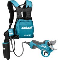
| Installing water supply |
| Loosen the screw A. Slide the tank holder all the way over the motor housing so that the notch of the band (part of the tank holder) is positioned just below the screw head of the tool as illustrated. Then tighten the screw A. Fig.11: 1. Screw A 2. Tank holder 3. Motor housing 4. Notch of the band (part of the tank holder) 5. Screw head of the tool Attach the tank on the tank holder so that the tank holder fits between the step and dots. Connect the cap on the tube end to the mouth of the tank. Turn the tank clockwise. Then tighten the screw B. Fig.12: 1. Tank 2. Tube 3. Screw B |
| Water supply |
| CAUTION: When filling the tank with water, be careful not to let the tool get wet. |
| Be sure that the water supply cock is closed before filling the tank with water. Open the cap on the tank and fill the water. Recap the tank. ▶ Fig.13: 1. Water supply cock 2. Close 3. Open ▶ Fig.14: 1. Cap 2. Open |
| OPERATION |
| CAUTION: This tool should only be used on horizontal surfaces. |
| CAUTION: Be sure to hold the workpiece firmly down on a stable bench or table during operation. |
| CAUTION: Do not twist or force the tool in the cut, or the motor may be overloaded or the workpiece may break. |
| CAUTION: Do not use the tool with the diamond wheel in an upward or sideways position. |
| CAUTION: The wheel for this tool is a wet-type diamond wheel for glass and tile applications. Be sure to feed water to the diamond wheel during operation. |
| CAUTION: If the cutting action of the diamond wheel begins to diminish, dress the cutting edge of the wheel using an old discarded coarse grit bench grinder wheel or concrete block. Dress by pressing lightly on the outer edge of the diamond wheel. |
| NOTE: When the battery cartridge temperature is low, the tool may not work to its full capacity. At this time, for example, use the tool for a light-duty cut for a while until the battery cartridge warms up as high as room temperature. Then, the tool can work to its full capacity. NOTE: Make sure that the water supply cock is closed before operation. |
MAINTENANCE
CAUTION: Always be sure that the tool is switched off and the battery cartridge is removed before attempting to perform inspection or maintenance.
NOTICE: Never use gasoline, benzine, thinner, alcohol or the like. Discoloration, deformation or cracks may result.
To maintain product SAFETY and RELIABILITY, repairs, any other maintenance or adjustment should be performed by Makita Authorized or Factory Service Centers, always using Makita replacement parts.
OPTIONAL ACCESSORIES
CAUTION: These accessories or attachments are recommended for use with your Makita tool specified in this manual. The use of any other accessories or attachments might present a risk of injury to persons. Only use accessory or attachment for its stated purpose.
If you need any assistance for more details regarding these accessories, ask your local Makita Service Center.
Diamond wheels
- Hex wrench
- Makita genuine battery and charger
NOTE: Some items in the list may be included in the tool package as standard accessories. They may differ from country to country.
SPECIFICATIONS
ACCESSIONS EN OPTION
VEILIGHEIDSWAARSCHUWINGEN
Algemene
OPTIONELE ACCESSOIRES
Móvo yia xwpe5 ts Eupwnns
H oumuoppwong EK Tepiauβavetai w
Papaptna A oTo npov Exyxipidio odnyiwv.
IPOEIAOIOIHSEI AΦAΛEIA
Evikc pOeioToIOeIg aOaAeiag Yia To nEKTpiko epyaeeio
A PPOEIAOIOIHSH: AiaBaoTe oLe Tc TPOeI- 0oioaeis yia thv aoPaleia kai oLe cTic Onyiec. H un npon TwV PPOeIOToiOnoeWv KAI Odyiw MTOpei va KataaN. Ei e NkEeKpOAnxi, TpuKayia n/kai oopapopaumuio.

- Intended use
- Noise
- Vibration
- EC Declaration of Conformity
- For European countries only
- SAFETYWARNINGS
- General power tool safety warnings
- Save all warnings and instructions for future reference.
- Cordless cutter safety warnings
- Kickback and related warnings
- Additional SafetyWarnings:
- SAVE THESE INSTRUCTIONS.
- Important safety instructions for battery cartridge
- Tips for maintaining maximum battery life
- FUNCTIONAL DESCRIPTION
- Installing or removing battery cartridge
- Battery protection system
- Overloaded:
- Low battery voltage:
- Indicating the remaining battery capacity
- Only for battery cartridges with the indicator
- Adjusting depth of cut
- Bevel cutting
- Sighti ng
- Switch action
- MAINTENANCE
- OPTIONAL ACCESSORIES
- ACCESSIONS EN OPTION
- VEILIGHEIDSWAARSCHUWINGEN
- OPTIONELE ACCESSOIRES
- IPOEIAOIOIHSEI AΦAΛEIA
- Evikc pOeioToIOeIg aOaAeiag Yia To nEKTpiko epyaeeio
Brand : MAKITA
Model : CC301D
Category : Scissors