BT DPRF01 - Thermostat Watts - Free user manual and instructions
Find the device manual for free BT DPRF01 Watts in PDF.

| Product type | RF programmable electronic thermostat |
| Power supply | 2 AAA LR03 alkaline batteries 1.5 V |
| Battery life | Up to 2 years (depending on battery quality) |
| Comfort and ECO setpoint range | 5 °C to 35 °C in 0.5 °C steps |
| Frost protection setpoint range (holiday mode) | 0.5 °C to 10 °C |
| Timer setpoint range | 5 °C to 35 °C |
| Measurement accuracy | 0.1 °C |
| Control type | Proportional band 2 °C (cycle 10 min) or hysteresis 0.5 °C; min ON/OFF time 2 min |
| Operating temperature | 0 °C to 40 °C |
| Storage temperature | -10 °C to +50 °C |
| Protection rating | IP30 |
| Electrical class | Class II |
| Radio frequency | 868 MHz |
| Radio power | < 10 mW |
| Internal sensor type | NTC 10 kΩ at 25 °C |
| Main functions | Weekly programming (30 min steps), manual Comfort/ECO modes, Off, Automatic, Program, Holiday, Timer, temporary override, Frost protection, keypad lock, auto summer/winter change, ITCS optimization, sensor calibration |
| Programming | 9 preset programs (P1-P9) and 4 user programs (U1-U4) |
| Maintenance and cleaning | Clean with a soft, dry cloth; do not use liquids or abrasive products |
| Safety | Disconnect power before any intervention; installation by qualified personnel; comply with standard NF C15-100; device not waterproof |
Frequently Asked Questions - BT DPRF01 Watts
User questions about BT DPRF01 Watts
0 question about this device. Answer the ones you know or ask your own.
Ask a new question about this device
Download the instructions for your Thermostat in PDF format for free! Find your manual BT DPRF01 - Watts and take your electronic device back in hand. On this page are published all the documents necessary for the use of your device. BT DPRF01 by Watts.
USER MANUAL BT DPRF01 Watts
BT DPRF-01
USER GUIDE GB
RF Digital programmable Thermostat 3-49
GUIDE D'UTILISATION F
RF Digital programmable Thermostat 50-95
GUÍA DE USUARIO ES
Termostato digital programable RF 96-141
Before starting work the installer should carefully read this Installation & Operation Manual, and make sure all instructions contained therein are understood and observed.
- The thermostat should be mounted, operated and maintained by specially trained personnel only. Personnel in the course of training are only allowed to handle the product under the supervision of an experienced fitter. Subject to observation of the above terms, the manufacture shall assume the liability for the equipment as provided by legal stipulations.
- All instructions in this Installation & Operation manual should be observed when working with the controller. Any other application shall not comply with the regulations. The manufacturer shall not be liable in case of incompetent use of the control. Any modifications and amendments are not allowed for safety reasons. The maintenance may be performed by service shops approved by the manufacturer only.
- The functionality of the controller depends on the model and equipment. This installation leaflet is part of the product and has to be obtained.
4
2
3
APPLICATION
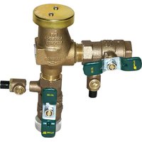
- The thermostats of the "BT" series are developed to control and manage all type of heating installations.
- The controllers have been designed for use in residential rooms, office spaces and industrial facilities.
Verify that the installation complies with existing regulations before operation to ensure proper use of the installation.
SAFETY INSTRUCTIONS
Before starting work disconnect power supply!
- All installation and wiring work related to the thermostat must be carried out only when de-energized. The appliance should be connected and commissioned by qualified personnel only. Make sure to adhere to valid safety regulations.
- The thermostats are neither splash- nor drip-proof. Therefore, they must be mounted at a dry place. - Do not interchange the connections of the sensors and the 230V connections under any circumstances! Interchanging these connections may result in life endangering electrical hazards or the destruction of the appliance and the connected sensors and other appliances.
5
Table of content
| 1 | Presentation | 7 |
| 1.1 | Keyboard | 9 |
| 1.2 | Display & LED | 10 |
| 2 | First Installation | 12 |
| 2.1 | Batteries installation | 12 |
| 2.2 | Time and Date adjustment | 13 |
| 2.3 | RF installation | 14 |
| 2.4 | Starting | 17 |
| 3 | Working mode definition | 19 |
| 3.1 | Manual mode Comfort | 20 |
| 3.2 | Manual mode, Reduced | 20 |
| 3.3 | OFF mode | 20 |
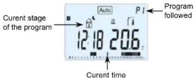
| 3.4 | Automatic mode | 21 |
| 3.5 | Program mode | 22 |
| 3.6 | Holiday mode | 33 |
| 3.7 | Timer mode | 34 |
| 4 | Special function | 35 |
| 4.1 | Keyboards lock Function | 35 |
| 4.2 | Information | 35 |
| 5 | Parameter's menu | 37 |
| 6 | Technical characteristics | 42 |
| 7 | Troubleshooting & Solution | 44 |
6
1 Presentation
Electronic programmable thermostat with LCD display specially designed to control different type of heating systems.
了
It will be your best partner to optimize your energy consumption and increase your comfort.
- Modern design with soft touch material.
- Wiring & Installation simplified.
- "Easy program creation" function.
- Weekly programmable by step of 30min.
- Temporary override function.
- Anti freeze function.
- Holiday or Reception function.
- EEPROM non volatile memory.
- 2 AAA batteries for 2 years operating life.
- 2 Wires output for a maximum possibility of use.
- 2 parameter menus, (User and Installer)
In option
- External sensor with several possibilities of regulation. (Floor, combined...)
8
1.1 Keyboard
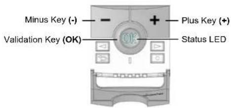
Left Navigation key (◀)
Right navigation key (▶)
Escape key (→)
Edition key (●)
y
1.2 Display & LED

Red Fix (when backlight is lit up): Heating demand
Green flash: your validation is required Red flash: Error on sensor or batteries
10
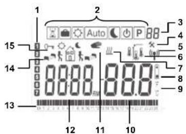
- Current day of the week
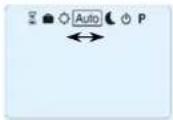
- Operating mode menu (active mode is framed).
- Program number or parameter number if "4" is displayed.
- Installation Parameter menu.
- RF transmission logo.
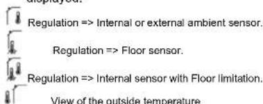
- Type of sensor used and temperature displayed.
- Heating demand indication.
- Low batteries indicator.
- °C or °F unit indicator
- Setting or measured temperature if "5" is displayed. Parameter value if "4" is displayed.
11
-
Temporary override function activated, or "ITCS" function if blinking.
-
Time or parameter title if "4" is displayed.
-
Program of the current day (the current time bar blinks)
-
Pictogram for program creation, program state in normal operating mode.
-
Key lock indicator
2 First Installation
This section will guide you to set up your thermostat for the first time.
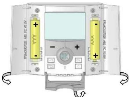
2.1 Batteries installation
- Open the two side's covers and Insert the 2 AAA Alkaline supplied batteries (or remove the small protection sticker if the batteries are already installed in the compartment)
- Close the two side's covers.
12
- Now your thermostat will propose you to adjust the current time and date.
2.2 Time and Date adjustment
Each time a value blinks, you can adjust it with the
(-) and (+) keys, once the value is chosen, validate
it with the (OK) key. The thermostat will jump
automatically to the next value.
Note: you can always come back to the previous
value by pressing the escape key (→)
List order of the time and date adjustments:
Time and day:
Adjustment of the hours,
Adjustment of the minutes
Adjustment of the day (1 = Monday)
Date:
Adjustment of the day number
Adjustment of the month number (01 to 12)
Adjustment of the year (Century)
Adjustment of the year
13
thermostat has received. (The heating is generally showed by a Red LED).
- Now return to the thermostat and switch off it.
Check on the receiver again if it's also switched off (The red LED must be turned off)
- If the RF signals were received correctly, adjust your setting temperature as you want.
- If the RF signals weren't received correctly, check the installation (Receiver position, distance...)
* To make the installation easier it will be better to have the thermostat near to the receiver during the configuration mode. (A minimal distance of >1 meter must be respected)
16
Then the message "Save" and blinking green LED appears, press (OK) to validate the adjusted time and date.
You can always reach the time and date adjustments, by pressing and maintaining the edition (●) key during 2 seconds in normal operating modes.
2.3 RF installation
- First of all to configure your thermostat with the receiver, you must put your receiver in « RF init ». mode. (please refer to the receiver leaflet for this, only the RF receiver of the same range are compatibles)
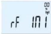
- Now on the thermostat press and maintain the edition key (●) during 10s, then the parameter « ini » must be display.
14
2.4 Starting
The thermostat is now ready to works.
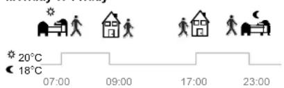
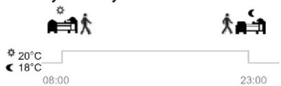
The default working mode will be automatic Auto with a standard built-in program "P1".
Monday to Friday
Saturday & Sunday
17
The thermostat will send now the radio configuration signal to the receiver.
- On the receiver check the good reception (generally showed by a green LED blinking). Once the configuration between the receiver and the thermostat made, press on the escape key (→) to come back to the main screen.
- Now you can check the RF distance, go to the room which must be regulated. Put your thermostat on the final position (On the wall or table...), then put the thermostat in Comfort mode (setting temperature position 37°C). Close the door and go to the receiver to check if the new status of the
15
Note:
You can customise your program as you want, See the next part "Working mode definition" chapter "Program" for more explanation.

At any time, when the backlight is extinct, press the (OK) key to lit-up the backlight, and then press another time the (OK) key to show the current setting temperature.
18
3 Working mode definition
How to change the working mode?
- Open the small center cover to have access to the navigation keys (◀) or (▶).
- You can now press theses keys to display the working mode line. Move the frame cursor on the desired working mode and press (OK) to enter in the operating mode you have chosen.
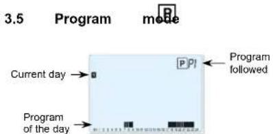
When you enter in the Program mode, the first operation is to chose the program number with (-) or (+) keys.
You can choose between a built-in program P1 to P9 or a user program U1 to U4.
3.1 Manual mode Comfort Manual working mode, the comfort setting temperature will be followed all the time. By pressing (-) or (+) keys, the comfort setting temperature starts to blink and can be adjusted.
3.2 Manual mode, Reduced Manual working mode, the reduced setting temperature will be followed all the time. By pressing (-) or (+) keys, the reduced setting temperature starts to blink and can be adjusted.
3.3 OFF mode Use this mode if you need to switch off your installation.
Be Careful: In this mode your installation can freeze.
20
If you chose a Built-in program P1 to P9, You can only see and chose the program.
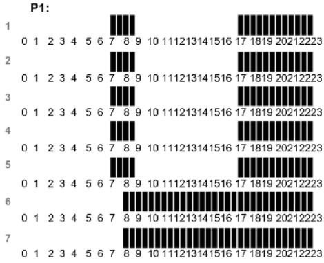
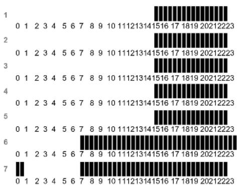
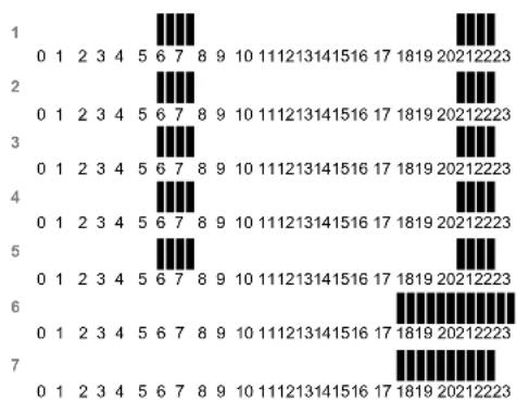
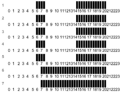
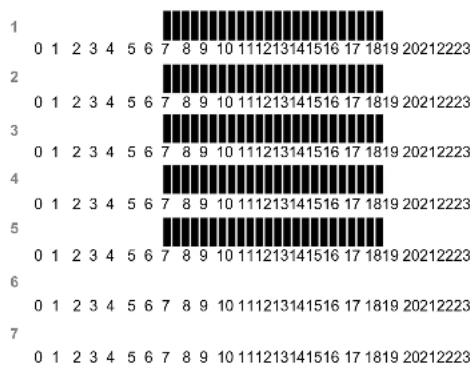
P1: Morning, Evening & Weekend
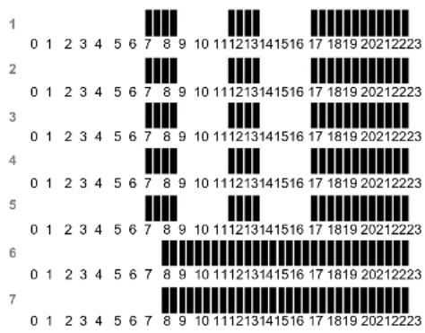
P2: Morning, Midday, Evening & Weekend
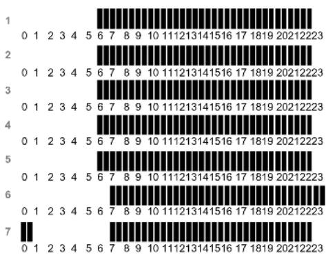
P3: Day & Weekend
P4: Evening & Weekend
P5: Morning, Evening (Bathroom)
P6: Morning, afternoon & Weekend
P7: 7H – 19H (Office)
P8: 8H – 19H & Saturday (Shop)
P9: Weekend (Secondary house)
(See the Annexe parts to view a complete description of the Built-in program)
- Use the navigation keys (◀) or (▶) to change the program day displayed.
- Press the (OK) key to confirm your choice and come back to the main screen (in AUTO mode)
23

- At any time, when display is off, press on the (Ok) key to display a few seconds the current temperature and time. - To restart your installation, use the navigation keys (◀) or (▶).
3.4 Automatic mode
In this mode the thermostat will follow the chosen program (Built-in or customized) according to the actual time and the Comfort and Reduced setting temperatures.
You can easily override, until next program step, the current program temperature by changing the value with (-) or (+). Setting temperature will blink. The small hand 📁 go will be displayed when override function is active. If hand 📁 go blinks then ITCS is ongoing.
21
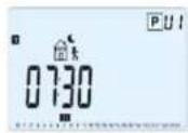
If you chose a user program U1 to U4,
As above you can choose the program, see it, but you can also customise it.
Default setting: U1, U2, U3, U4 = Comfort all week
- Press on the edition key (●) to customise a user program.
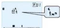
Symbols and explanation for program creation:
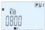
First step of the day (Comfort temp.) The wakeup hour need to be adjusted.
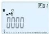
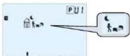
Middle step of the day ( Reduced temp.) The leaving hour need to be adjusted
24

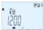
Middle step of the day (Comfort temp.)
The comeback hour will need to be adjusted

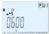
Last step of the day ( Reduced temp.)
The sleeping hour need to be adjusted
- The program step is 30 minutes
- Each time a value or icon blinks you are invited to make a choice with (-) or (+) keys, once the choice is made press the (OK) key to jump to the following step.
- The program creation will always start with the day 1 (Monday).
Once you have pressed the (●) key, the following display will appear:
25
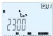
When step hour is set press (OK) to jump to the next step.
You will be directly invited to adjust with (-) or (+) the hour of the comeback step.
28
Now you are invited to adjust the hour of the first step of the program with (-) or (+).
Press (OK) to validate and go to the following step.
26
Press (OK) to validate and go to the following step.
You are again invited to choose the type of the next step of the program (blinking icons),
2 choices will be possible:
- 1 ^st choice is to choose the sleep icons. (End of the day)
- 2 ^rd choice is to choose the leaving icons, to add another step to the program during the day.
29
Now you are invited to choose the type of the next step of the program (blinking icons),
2 choices will be possible:
- 1 ^st choice is to choose the sleep icon. (End of the day)
- 2^nd choice is to choose the leaving icon, to add one step to the program during the day.
When the choice is made, press (OK) to validate. Then you can adjust the step hour with (-) or (+),
27
When the choice is made, press (OK) to valid and you can adjust the hour of this step with (-) or (+),
Press (OK) to validate and finish the edition of the first day.
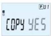
Now you can choose to copy the program day just created to subsequent days.

30
Change the choice "Yes" or "no" with (-) or (+) and validate your choice with (OK).
- If you select "no", you will be invited to create a program for Tuesday (repeat the previous method to built it.)
- If you select "Yes", you will have the possibility to copy the program to the following day (on Tuesday on Wednesday... up to the last day of the week (7 Sunday).
When you press (OK) on the last day (7 Sunday) you will be invited to "SAVE" your program.
Then the message "Save" and blinking green LED appears:
31
3.7 Timer mode

The Timer mode allows you to adjust, the temperature and the duration for a special time. This function can be used when you stay at home for several days, or if you want to override the program for some time (reception...)
- You can first adjust, the duration in hours "H" if below 24H, then in day "d" with (-) or (+), press (OK) to validate. (Adjustable 1 Hour to 99 days)
- In a second time, you can adjust the desired setting temperature with (-) or (+), press (OK) to start the function. (Default value 22°C)
The 📄 logo will be blinks and the number of hours /days left is displayed until the end of the period.

If you want to stop the Timer function before the end, set the duration period to "no" with (-) key.
34

Press (OK) key to save your program and return to AUTO operating mode following your user program.
Press the escape key (→) to erase your user program changes and come back to operating mode.
32
4 Special function
4.1 Keyboards lock Function

Use this function to prevent all change of your settings (In a child room, public area...)
- To activate the Key lock function, first press maintain the escape key (▶) and then press simultaneously on the edition key (●).
- The "0" logo will be displayed on the screen. - Repeat the same procedure to unlock the key board.
4.2 Information
With this function You can quickly view all currents temperatures of the probe sensors connected to your thermostat (Floor, external or outside sensor) by several presses on the escape key (→). This "Scroll function" is only available in the main screen.
35
3.6
Holiday

The Holiday mode allows you to set the anti-freeze temperature for a selected number of days
- You can adjust, the duration in day "d" with (-) or (+), press (OK) to start. (Adjustable 1 to 99 days)
- The anti-freeze setting temperature is fixed and can be adjusted in the parameter menu number 06 'HG', see chapter 6. (Default value 10°C)

o will blink and the number of days left ed until the end of the period.

If you want to stop the Holiday function before the end, set the duration period to "no" with (-) key.
33
You can view:
- The current setting temperature followed by the thermostat.
- The ambient temperature
- If external sensor is connected:
The Floor temperature if it is used as floor sensor. The outside temperature if it used as outside sensor.

If Parameter "SenS" is set on "Air", the external sensor will be used as an outside temperature sensor
36
5 Parameter's menu
Your thermostat has a parameter's menu, in order to enter in this menu, press and maintain the edition key (●) during 5sec. Then parameter menu will appear and first parameter screen will be displayed:
Now you can select a parameter which must be adjusted with the navigation keys (◀) or (▶), once the parameter chosen, toggle the value with the (OK) key, modify it with (-) or (+) and confirm your adjustment with (OK).
37
To leave the parameter menu, choose the parameter « End » and press (OK).
| N° | Default value & other possibilities |
| 00 | RF INI: Radio configurationSends the radio link signal in order to assign this RF Thermostat with it's RF receiver.You also need to set simultaneously the receiver in radio configuration mode (On a simple receiver press and maintain button until the green light lit's up, see receiver leaflet) |
| 01 | deg: Unit of the temperatures displayed°C Celsius°F Fahrenheit |
| 02 | —:Selection of the Time clock unit24H (24:00)12H (12:00 AM /PM) |
| 03 | dst: Daylight Summer time change Summer<->WinterYES automatic change according to date.no no daylight summer time automatic change. |
38
| 04 | Airc: Calibration of the internal probeThe calibration must be done after 1 day working with the same setting temperature in accordance with the following description:Put a thermometer in the room at 1.5M distance from the floor (like the thermostat) and check the real temperature in the room after 1 hour.When you enter on the calibration parameter “no” is displayed on the right to indicate no calibration has made.To enter the value shown on the thermometer, use the (-) or (+) keys to enter the real value. Then, press (Ok) to confirm.The message “Yes” should be displayed; the value will be stored in the internal memory.If you need to erase a calibration press on the escape key (→).The old value will be erased and the message “no” will be displayed.* Pay attention:Only the healing element driven by the thermostat must be used during the complete step of the calibration. |
39
| 05 | OutC , AMbC , FlrC: Calibration of the external wired probeSame calibration method as described in parameter "04 Airc" above. |
| 06 | HG: Anti-freeze temperature used in Holiday modeDefault value 10°C.Use the (-) or (+) keys to change the anti-freeze setting temperature. Then press (Ok) to confirm. |
| 07 | ITCS: YES, noThe Intelligent Temperature Control System will activate your installation in advance (2 hours maximum) to assure the desired temperature at the hour programmed following your weekly program.This automatic control system works in the following way:When you start your thermostat for the first time, it will measure the time taken by your installation to reach the set temperature. The thermostat will re-measure this time at each program change to compensate external temperature change & Influence. You can now program your thermostat without the need to adjust the temperature in advance because your thermostat does it automatically for you. |
40
| 08 | Clr ALL: Reset to Factory settingPress and maintain (Ok) key during 10s to reset Set points temperatures and user parameters in this menu to factory default settings. User programs will also be resetted.^A Pay attention:Ensure you that you have all necessary elements to re-setup your installation before to use this function. |
| 09 | Software versionVErs ____ |
| 10 | End: Exit the parameter's menuPress (OK) key to exit installation parameter menu and return to normal operation. |
41
6 Technical characteristics
| Environmental:Operating temperature:Shipping and storagetemperature: | 0°C - 40°C-10°C to +50°C |
| Electrical ProtectionInstallation CategoryPollution Degree | IP30Class II2 |
| Measured temperatureprecision | 0.1°C |
| Setting temperature rangeComfort, ReducedHoliday (Antifreeze)Timer | 5°C to 35°C by 0,5°C step10°C (adjustable)5°C to 35°C |
| Regulation characteristics | Proportional Band (PWM2°C for 10min cycle) orHysteresis of 0.5°C |
| Power SupplyOperating life | 2 AAA LR03 1.5V Alkaline~2 years |
| Sensing elements:Internal & External (option) | NTC 10kΩ at 25°C |
42
| Radio Frequency 868 MHz, <10mW. | |
| Software version | Showed in the parameter menu. Vers xxx |
| Norms and homologation:Your thermostat has been designed in conformity with the following standards or other normative documents: | EN 60730-1 : 2003EN 61000-6-1 : 2002EN 61000-6-3 : 2004EN 61000-4-2 : 2001EN300220-1/2EN301489-1/3R&TTE 1999/5/ECLow voltage 2006/95/CEEMC 2004/108/CE |
43
7 Troubleshooting & Solution
| My BT DP-01 doesn't start | |
| Batteries Problem | - Check if the protection sticker on the batteries is removed.- Check the batteries orientation.- Check the capacity of the batteries |
| My BT DP-01 Led, blinks in Red | |
| Problem on sensors | The logo blinks (ambient sensor)- Contact your installer or seller.The logo blinks (Floor sensor)- Check the connection of the sensor.- Disconnect the sensor, and check it with an ohmmeter(the value must be around 10kohms) |
44
| Batteries level istoo less | The logo blinks (Batteries)- Replace the batteries. |
| My BT DP-01 seems work correctly but the heating doesn'twork correctly | |
| Output | On the receiver:- check the good reception of RFsignal- Check the connections.- Check the power supply of theheating element.- Contact your installer. |
| RFcommunication | - Check the following points :- The receiver must be put at aminimum distance of 50cm of allothers electrical or wirelessmaterials (GSM, Wi-Fi...) - The receiver shouldn't be fixed ona metallic part or too close ofhydraulic pipes... (Copper...) |
45
| My BT DP-01 seems work correctly but the temperature in the room was never in accordance with the program. | |
| Program | - Check the Clock.-The difference between Comfort & Reduced temperature is too high?- The step in the program is too short?- Contact your installer, to check & adjust the regulation parameters with your healing system. |
46
47

IMPORTANT!
P1: Matin, Soir & Weekend
P2: Matin, Midi, Soir & Weekend
P3: Semaine & Weekend
P4: Soir & Weekend
P5: Matin, Soir (Salle de Bain)
P6: Matin, Après midi & Weekend
P7: 7H - 19H (Bureau)
P8: 8H - 19H & Samedi (Magasin)
P9: Weekend (Maison secondaire)
70
Electronische programmeerbare thermostaat met LCD display.
192
U1, U2, U3, U4 = Comfort de hele week
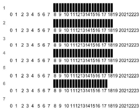
Annexes (Built-in Program description)
278
P2:
279
P3:
280
P4:
281
P5:
282
P6:
283
P7:
284
P8:
285
P9

bar
| Category | Value | |---|---| | 1 | 0 | | 2 | 0 | | 3 | 0 | | 4 | 0 | | 5 | 0 | | 6 | 0 | | 7 | 0 |286

PPLIMP09726Ca rev : 28/03/11