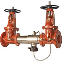
957-OSY-FS - Pump Watts - Free user manual and instructions
Find the device manual for free 957-OSY-FS Watts in PDF.


User questions about 957-OSY-FS Watts
0 question about this device. Answer the ones you know or ask your own.
Ask a new question about this device
Download the instructions for your Pump in PDF format for free! Find your manual 957-OSY-FS - Watts and take your electronic device back in hand. On this page are published all the documents necessary for the use of your device. 957-OSY-FS by Watts.
USER MANUAL 957-OSY-FS Watts
Installation, Maintenance, and Repair Manual Series 957, 957RPDA, LF957RPDA
Reduced Pressure Zone Assemblies Reduced Pressure Detector Assemblies
2^1/2 - 10"
! WARNING

THINK SAFETY FIRST
Read this Manual BEFORE using this equipment. Failure to read and follow all safety and use information can result in death, serious personal injury, property damage, or damage to the equipment. Keep this Manual for future reference.
WARNING
Local building or plumbing codes may require modifications to the information provided. You are required to consult the local building and plumbing codes prior to installation. If the information provided here is not consistent with local building or plumbing codes, the local codes should be followed. This product must be installed by a licensed contractor in accordance with local codes and ordinances.
WARNING
Need for Periodic Inspection/Maintenance: This product must be tested periodically in compliance with local codes, but at least once per year or more as service conditions warrant. All products must be retested once maintenance has been performed. Corrosive water conditions and/or unauthorized adjustments or repair could render the product ineffective for the service intended. Regular checking and cleaning of the product's internal and external components helps assure maximum life and proper product function.
WARNING
This device must be tested periodically in compliance with local codes, but at least once per year or more as service conditions warrant. If installed on a fire sprinkler system, all mechanical checks, such as alarm checks and backflow preventers, should be flow tested and inspected internally in accordance with NFPA 13 and NFPA 25.
WARNING
Do not impede or prevent sleeve movement by installing riser cradle clamps or other obstructive elements on or around the sleeve. Sleeve movement is required to service the backflow.
Testing
For field testing procedure, refer to Watts installation sheets IS-TK-DL, IS-TK-9A, IS-TK-99E and IS-TK-99D at www.watts.com.
For Australia, refer to Australian standard AS/NZS 2845.3.
For technical assistance, contact your local Watts representative.
natural_image
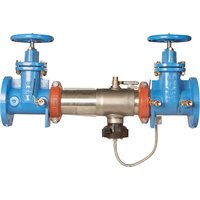
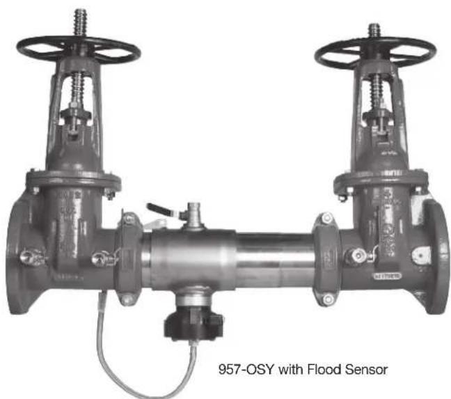
Industrial valve assembly with two flanged arms and a central pipe fitting, labeled '957-OSY with Flood Sensor' (no other text or symbols visible)Series 957, 957RPDA, and LF957RPDA each include a flood sensor on the relief valve to detect excessive discharge and trigger notification of potential flood events.
NOTICE
An add-on connection kit is required to activate the flood sensor. Without the connection kit, the sensor is a passive component that has no communication with any other device. (A retrofit connection kit is also available for existing installations. See "Add-on and Retrofit Sensor Connection Kits," for ordering details.)
NOTICE
Use of the flood sensor does not replace the need to comply with all required instructions, codes, and regulations related to installation, operation, and maintenance of this product, including the need to provide proper drainage in the event of a discharge.
Watts is not responsible for the failure of alerts due to connectivity issues, power outages, or improper installation.
NOTICE
For Australia and New Zealand: Pipeline strainers should be installed between the upstream shutoff valve and the inlet of the backflow preventer.
Fittings such as end connectors intended to join alternative pipe systems made from other materials (such as plastics) shall also conform to the relevant dimensional and performance requirements of the appropriate Australian, New Zealand, or joint Australian–New Zealand Standard for the alternative pipe system.
Installation Guidelines
- Most field problems occur because dirt and debris are present in the system at the time of installation and becomes trapped in check No. 1. The system should be flushed before the backflow valve is installed. If the system is not flushed until after the backflow valve is installed, remove both check modules from the valve and open the inlet shutoff to allow water to flow for a sufficient time to flush debris from the water line. If debris in the water system continues to cause fouling, a strainer can be installed upstream of the backflow assembly.
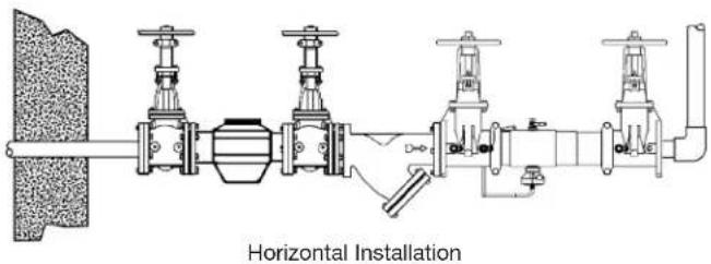
- Series 957, 957RPDA, and LF957RPDA can be installed in either horizontal, "N" pattern, or "Z" pattern position as long as the backflow assembly is installed in accordance with the direction of the flow arrow on the assembly and the local water authority approves the installation.
- The assembly should be installed with adequate clearance around the valve to allow for inspection, testing, and servicing. Ensure a minimum clearance of 12" between the lower portion of the assembly and the floor or grade. The valve should be protected from freezing.
- Installing a backflow preventer in a pit or vault is not recommended.
- Normal discharge and nuisance spitting are accommodated by the use of a Watts air gap fitting and a fabricated indirect waste line. A floor drain appropriately sized for the discharge must be provided in case of excessive discharge. For more information, download ES-RVD for relief valve discharge rates.
- When installing an air gap, attach the air gap brackets directly onto the flood sensor.
- Have a certified technician test the series at the time of installation.
NOTICE
Assembly body should not be painted.
text_image
Horizontal Installation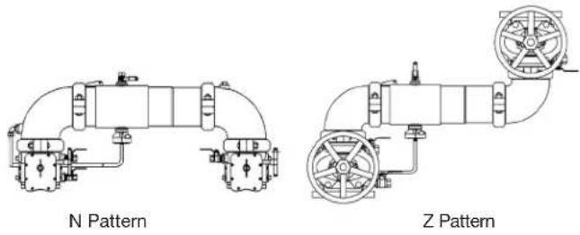
text_image
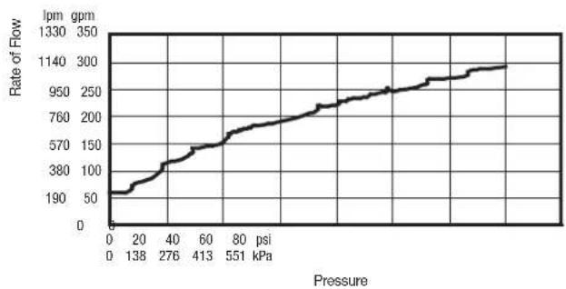
N Pattern Z PatternRelief Valve Discharge Rates 2½" - 10"
line
| Pressure (kPa) | Rate of Flow (lpm gpm) | | -------------- | ---------------------- | | 0 | 50 | | 20 | 100 | | 40 | 150 | | 60 | 200 | | 80 | 250 | | 100 | 300 |Maintaining the Check Modules
2^1/2 -6"
Housing
natural_image
Mechanical component diagram showing a cylindrical shaft with a spring and valve, no text or symbols presentFigure A
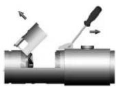
Figure B
natural_image
Mechanical component with cylindrical body and multiple ports (no visible text or symbols)Figure C
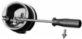
Check No. 1
natural_image
Mechanical component diagram showing a lever and shaft assembly (no text or symbols)Figure D
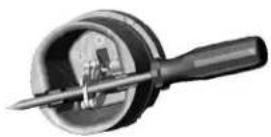
Figure E
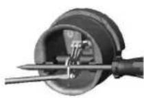
Figure F
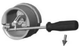
Check No. 2
natural_image
Mechanical tool with a circular component and a downward arrow indicating motion (no text or symbols)Figure D
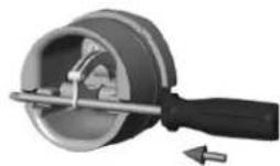
Figure E
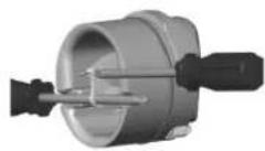
Figure F
WARNING
Before servicing any Watts valve, it is mandatory to shut down the water system by closing both the inlet and outlet shutoff valves. After the shutoff valves are closed, open test cocks No. 2, No. 3, and No. 4 to relieve pressure within the backflow assembly.
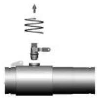
- After test cock No. 3 has been opened to relieve pressure, remove the test cock from the housing. (See Figure A.)
- Insert a #3 screwdriver through the hole on the top of the cover sleeve and using both hands rotate the cover sleeve approximately a quarter turn clockwise and a quarter turn counterclockwise to break the sleeve O-ring seals. Using the screwdriver, slowly slide the cover sleeve to the downstream side of the housing. (See Figure B.)
- Remove the stainless steel check retainer from the housing. (See Figure B.)
-
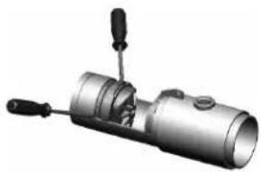
Remove the check No. 1 module by inserting two flat blade screwdrivers into the slots on either side of the check module and gently pry the check module toward the open zone. (See Figure C.)
-
Repeat step 4 to remove check No. 2 module. (For servicing 6" checks, see the maintenance instructions for valve sizes 8" to 10".)
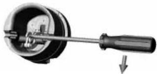
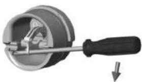
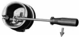
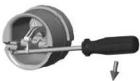
- To clean or inspect either check module, insert a #3 screw-driver through the downstream side of the check module. (See Figures D and E.) When the screwdriver is in place, remove the E-clip and pin connecting the structural members. (See Figure F.) The check clapper opens with no tension.
- Thoroughly clean the seating area. The sealing disc can be removed, if necessary, by detaching the screws connecting the keeper plate to the clapper. Reverse and reinstall the sealing disc if the elastomer is cut or damaged.
- Wash the check module and O-ring and inspect for any damage. If damaged, reinstall new parts.
- After a thorough cleaning, lubricate the O-ring with an FDA Approved lubricant, replace the pin and E-clip in the structural members, remove the screwdriver, and reinstall the check modules. Reverse the order of these steps to reassemble the parts and housing.
Maintaining the Check Modules
8" - 10"
Tool Requirements
-
3 Phillips screwdriver or ^5/16 " diameter rod, length sufficient to span the diameter of the checks (See Figures A and B.)
- 1/2'' - 13 x 5 fully threaded hex bolt (service bolt)
- ^3/_4 " open end or socket wrench
Instructions
WARNING
Before servicing any Watts valve, shut down the water system by closing both the inlet and outlet shutoff valves. This is mandatory. After the shutoff valves are closed, open test cocks No. 2, No. 3, and No. 4 to relieve pressure within the backflow assembly.
- After test cock No. 3 has been opened to relieve pressure, remove the test cock from the housing. (When repairing an 8" or 10" device, remove both Victaulic couplers from the body. Slide the downstream Victaulic coupler gasket to the downstream side of the housing. The upstream Victaulic coupler gasket stays in place.)
- Remove the check(s) to be serviced.
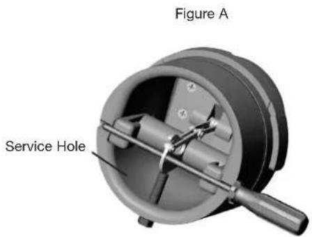
- Locate the service hole and thread in the service bolt by hand until it contacts the linkage. (See Figure A.)
- Continue to thread in service bolt with the wrench until the service hole in the linkage is aligned with the service notches on the spring arbors. (See Figure A.)
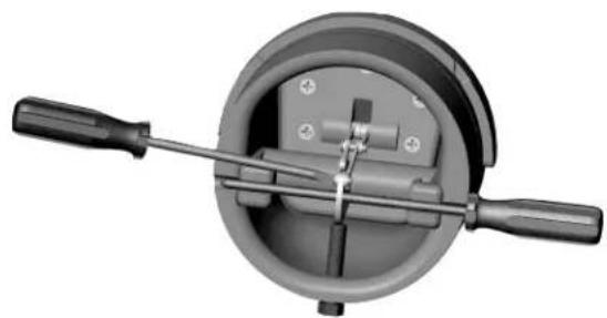
- Insert the Phillips screwdriver through the arbors and service hole of the linkage making sure that the tip of the screwdriver extends past the ends of the arbors by a minimum of 14 ". (See Figure B.)
- Loosen the service bolt until the load is transferred to the screwdriver. Continue to loosen the service bolt until there is sufficient clearance to remove the complete spring mechanism.
- To disconnect the linkage, remove the retaining clip and pin. Store both items in a safe location for reinstallation.
- To remove the spring mechanism, grasp the screwdriver at the center and pull the complete assembly straight out and store in a safe place.
- Reverse the order of these steps to reassemble the parts and housing.
WARNING
While the spring mechanism is being removed, never pull the screwdriver out or off the support notches on the arbors. Doing so may cause bodily injuries.
text_image
Figure A Service HoleFigure B
natural_image
Mechanical device with two handles and central hub (no visible text or symbols)Servicing the Relief Valve
WARNING
Before to servicing the relief valve, it is mandatory to shut down water system by closing both the inlet and outlet shutoff valves and relieving pressure within the assembly by opening test cocks No. 2, No. 3, and No. 4.
DO NOT REMOVE SPIDER BUSHING FOR SERVICING
- Detach the activation module, if installed, from the flood sensor.
- Use a #2 Phillips screwdriver to remove the sensor from the relief valve.
- Disconnect the hose from the bottom cover plate to the relief valve.
- An O-ring seals the relief valve body to the main housing. Avoid tightening the connection beyond firm hand tightening. Loosen the relief valve by hand to remove it, then unscrew the relief valve from the housing.
- Remove the cover plate of the relief valve by detaching the four connecting screws.
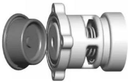
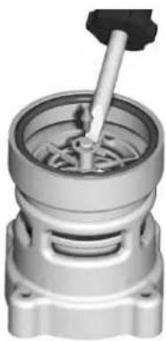
- Remove the rubber diaphragm from the relief valve. Notice how the diaphragm is configured to reinstall it in the same manner. The hard rubber tab in the diaphragm fits into a similar socket in the head of the piston. (See Figure A.)
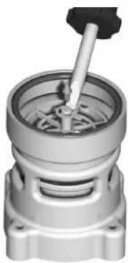
- Hold the relief valve in both hands with the threaded end up and both thumbs on the head of the piston. Push up on the piston until the piston shaft with the attached E-clip is exposed. Remove the E-clip. (See Figure B.)
- Remove the piston and spring from the relief valve housing and thoroughly clean all parts including the diaphragm. Inspect all rubber parts and replace any that are damaged.
- Reverse the order of these steps to reassemble the parts and housing.
Figure A
natural_image
3D cutaway view of a mechanical component showing internal parts and housing (no text or symbols)Figure B
natural_image
Mechanical component with a central shaft and circular housing (no visible text or symbols)Parts
text_image
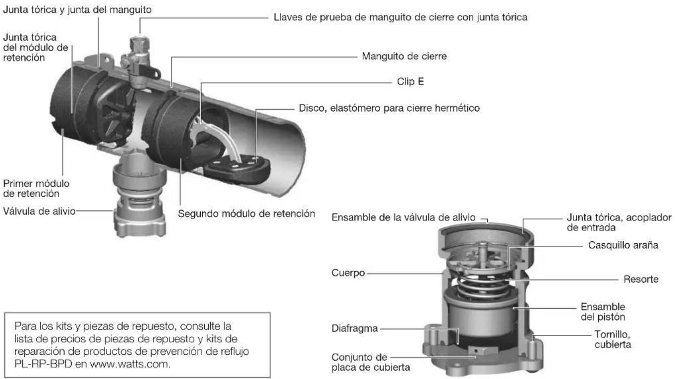
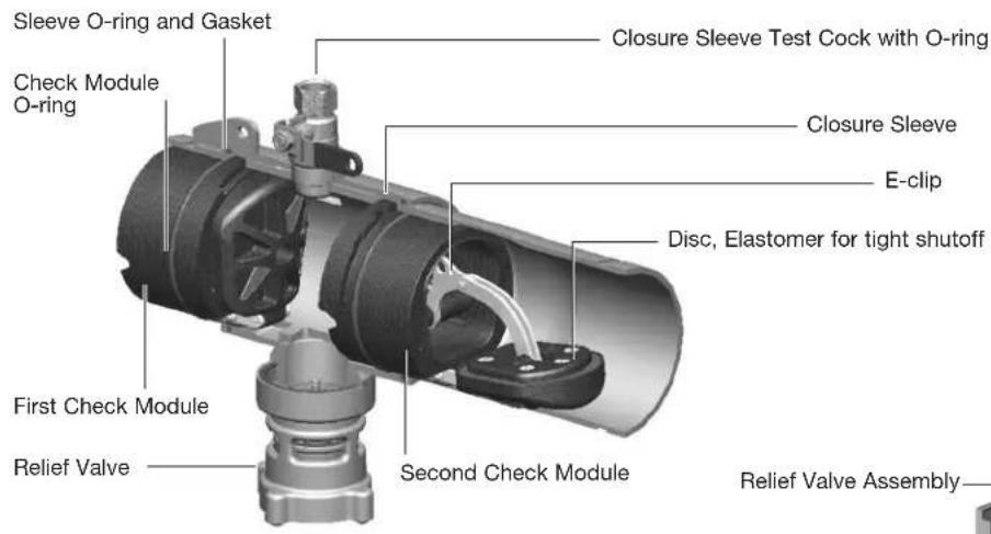
Sleeve O-ring and Gasket Check Module O-ring First Check Module Relief Valve Second Check Module Closure Sleeve Test Cock with O-ring Closure Sleeve E-clip Disc, Elastomer for tight shutoff Relief Valve AssemblyFor repair kits and parts, refer to the Backflow Prevention Products Repair Kits & Service Parts PL-RP-BPD price list at watts.com.
text_image
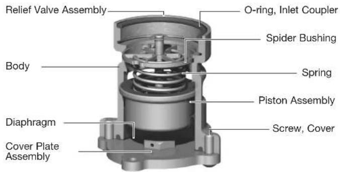
Relief Valve Assembly O-ring, Inlet Coupler Spider Bushing Body Spring Piston Assembly Diaphragm Screw, Cover Cover Plate AssemblyTroubleshooting
| SYMPTOM CAUSE SOLUTION | ||
| Relief valve discharges water while system is not flowing Check No. 1 is fouled Remove and clean check No. 1 | ||
| Relief valve does not properly close Service relief valve | ||
| Municipal water pressure is fluctuating Install check valve upstream of backflow assembly | ||
| Relief valve does not shut off properly Fouled relief valve seat Service relief valve | ||
| Incorrectly Installed diaphragm Remove diaphragm and correctly install | ||
| Damaged rubber surface on piston Replace with new piston | ||
| Damaged or plugged pressure hose Replace or clear pressure hose | ||
Add-on and Retrofit Sensor Connection Kits for Building Management Systems
| PART NUMBER ADD-ON/RETROFIT KIT DESCRIPTION | |||
| 88009418 FP-BF | 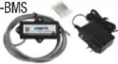 | BMS Sensor Connection KitSeries 957, 957RPDA, LF957RPDASeries 994, 994RPDASizes 212" to 10" | Includes sensor activation module with cable, ground wire, and power adapter. Use this kit to activate the flood sensor and enable flood detection capabilities on the relief valve of a new installation linked to a BMS controller (not included). |
| 88009419 FP-RFK-BF-RMC-DES | 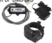 | BMS Sensor Retrofit Connection KitSeries 957, 957RPDA, LF957RPDASeries 994, 994RPDASizes 212" to 10" | Includes flood sensor, sensor activation module with cable, ground wire, and power adapter. Use this kit to install the flood sensor and enable flood detection capabilities on the relief valve of an existing installation linked to a BMS controller (not included). |
Add-on and Retrofit Sensor Connection Kits for Cellular Communication
| PART NUMBER ADD-ON/RETROFIT KIT DESCRIPTION | |||
| 88009420 FP-BF | 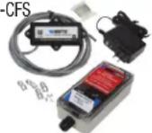 | Cellular Sensor Connection KitSeries 957, 957RPDA, LF957RPDASeries 994, 994RPDASizes 212 " to 10 " | Includes sensor activation module with cable, Cellular Gateway with mounting kit, ground wire, and power adapter. Use this kit to activate the flood sensor and enable flood detection capabilities on the relief valve of a new installation linked to a cellular network to send alerts by email message, SMS text message, or voice call. |
| 88009421 FP-RFI | 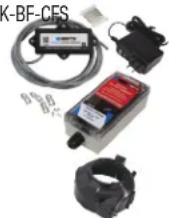 | Cellular Sensor Retrofit Connection KitSeries 957, 957RPDA, LF957RPDASeries 994, 994RPDASizes 212 " to 10 " | Includes flood sensor, sensor activation module with cable, Cellular Gateway with mounting kit, ground wire, and power adapter. Use this kit to install the flood sensor and enable flood detection capabilities on the relief valve of an existing installation linked to a cellular network to send alerts by email message, SMS text message, or voice call. |
Limited Warranty: Watts (the "Company") warrants each product to be free from defects in material and workmanship under normal usage for a period of one year from the date of original shipment. In the event of such defects within the warranty period, the Company will, at its option, replace or recondition the product without charge.
THE WARRANTY SET FORTH HEREIN IS GIVEN EXPRESSLY AND IS THE ONLY WARRANTY GIVEN BY THE COMPANY WITH RESPECT TO THE PRODUCT. THE COMPANY MAKES NO OTHER WARRANTIES, EXPRESS OR IMPLIED. THE COMPANY HEREBY SPECIFICALLY DISCLAIMS ALL OTHER WARRANTIES, EXPRESS OR IMPLIED, INCLUDING BUT NOT LIMITED TO THE IMPLIED WARRANTIES OF MERCHANTABILITY AND FITNESS FOR A PARTICULAR PURPOSE.
The remedy described in the first paragraph of this warranty shall constitute the sole and exclusive remedy for breach of warranty, and the Company shall not be responsible for any incidental, special or consequential damages, including without limitation, lost profits or the cost of repairing or replacing other property which is damaged if this product does not work properly, other costs resulting from labor charges, delays, vandalism, negligence, fouling caused by foreign material, damage from adverse water conditions, chemical, or any other circumstances over which the Company has no control. This warranty shall be invalidated by any abuse, misuse, misapplication, improper installation or improper maintenance or alteration of the product.
Some States do not allow limitations on how long an implied warranty lasts, and some States do not allow the exclusion or limitation of incidental or consequential damages. Therefore the above limitations may not apply to you. This Limited Warranty gives you specific legal rights, and you may have other rights that vary from State to State. You should consult applicable state laws to determine your rights. SO FAR AS IS CONSISTENT WITH APPLICABLE STATE LAW, ANY IMPLIED WARRANTIES THAT MAY NOT BE DISCLAIMED, INCLUDING THE IMPLIED WARRANTIES OF MERCHANTABILITY AND FITNESS FOR A PARTICULAR PURPOSE, ARE LIMITED IN DURATION TO ONE YEAR FROM THE DATE OF ORIGINAL SHIPMENT.
WWATTS®
USA: T: (978) 689-6066 • Watts.com
Canada: T: (888) 208-8927 • Watts.ca
Latin America: T: (52) 55-4122-0138 • Watts.com
natural_image
Mechanical valve assembly with two flanged arms and a central shaft, no visible text or symbols on the device itself.natural_image
Mechanical component with cylindrical body and multiple ports (no visible text or symbols)Figure C
Clapet n° 1
natural_image
Mechanical component with a lever and shaft, showing internal components and a downward arrow (no text or symbols)Figure D
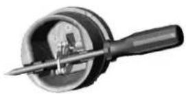
Figure E
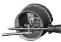
Figure F
Clapet n° 2
natural_image
Mechanical tool with a circular component and a downward arrow indicating motion (no text or symbols)Figure D
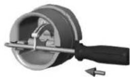
Figure E
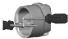
Figure F
AVERTISSEMENT
Exigences relatives aux outils
natural_image
Mechanical component diagram showing a circular housing with two handles and internal components (no text or symbols)natural_image
3D cutaway view of a mechanical component with no visible text or symbolsFigure B
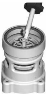
natural_image
Mechanical component with a central shaft and housing (no visible text or symbols)Pièces
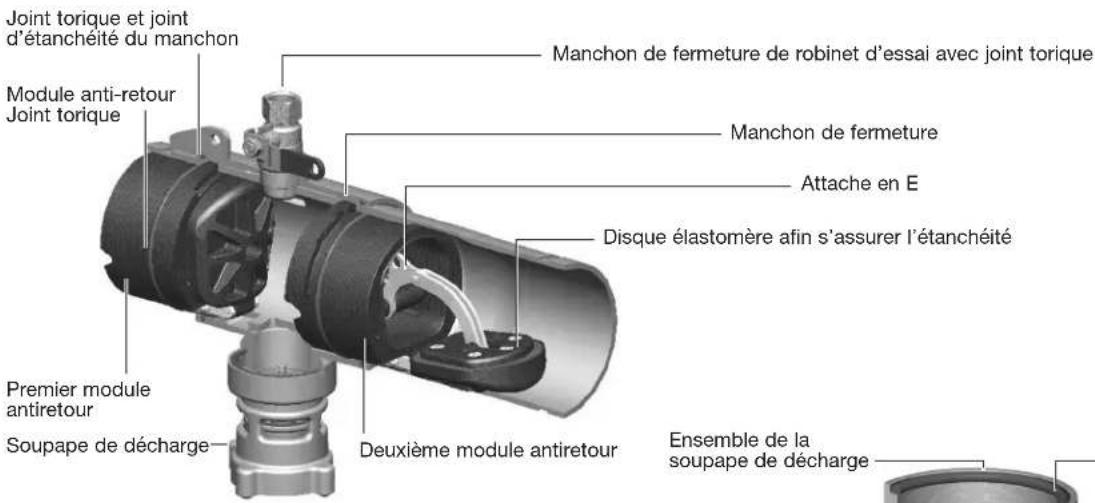
natural_image
Industrial valve assembly with two flanged arms and a central shaft, labeled '957-OSY con sensor de inundación' (no other text or symbols visible)natural_image
Mechanical component with cylindrical body and multiple ports (no visible text or symbols)Figura C
Retención n.° 1
natural_image
Mechanical component with a lever and shaft, showing internal parts without any text or symbolsFigura D
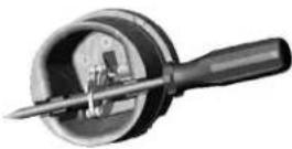
Figura E
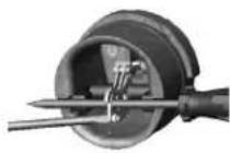
Figura F
Retención n.° 2
natural_image
Mechanical tool with a circular component and a downward arrow indicating motion (no text or symbols)Figura D
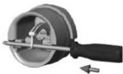
Figura E
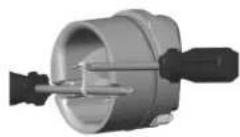
Figura F
ADVERTENCIA
natural_image
Mechanical device with two handles and central hub (no visible text or symbols)natural_image
3D cutaway view of a mechanical component with no visible text or symbolsFigura B
natural_image
Mechanical component with a central shaft and internal gear assembly (no visible text or symbols)Piezas