S 5004 - Heating Trumatic - Free user manual and instructions
Find the device manual for free S 5004 Trumatic in PDF.


Frequently Asked Questions - S 5004 Trumatic
User questions about S 5004 Trumatic
0 question about this device. Answer the ones you know or ask your own.
Ask a new question about this device
Download the instructions for your Heating in PDF format for free! Find your manual S 5004 - Trumatic and take your electronic device back in hand. On this page are published all the documents necessary for the use of your device. S 5004 by Trumatic.
USER MANUAL S 5004 Trumatic
GB Operating instructions To be kept in the vehicle!
Page
DK Brugsanvising Side 35 Skal medbringes i koretojet!
b = Piezo-Druckzünder (S 3004 P)
c = Blinddeckel
h = Thermostatfuhler
Symbols used 8
Safety instructions 8
Important operating notes 9
Intended use 9
Operating instructions
S 3004 / S 3004 P heating system 10
S 5004 heating system 10
Taking into operation 10
S 3004 P with Piezo push ignitor 10
S 3004 / S 5004 with auto ignitor 10
Operating the fan 11
Lighting 11
Room thermostat 11
Switching off 11
Maintenance 11
Cleaning (only with the device switched off!) 11
Remove cover 11
Attach cover 12
Battery change on the auto ignitor 12
Specific information 12
Disposal 12
Technical data 12
Dimensions 12
Declaration of conformity 13
Manufacturer's terms of warranty 13
Safety instructions
An opened skylight / lifting roof around the exhaust cowl involves the danger of exhaust gas entering the vehicle interior. The heater may only be operated when the roof skylight / lifting roof is closed.
The use of upright gas cylinders from which gas is taken in the gas phase is mandatory for the operation of gas regulators, gas equipment and gas systems. Gas cylinders from which gas is taken in the liquid phase (e.g. for fork lifts) must not be used, since they would result in damage to the gas system.
In case of gas system leaks or gas smell:
Put out all naked flames
-Do not smoke
- Switch off gas equipment
- Close gas cylinders
- Open windows and doors
- Do not use any electrical switches
- Allow the whole system to be checked by an expert!

Only experts may carry out repair work!
A new O-ring must be mounted each time the waste gas line is dismantled.
Guarantee claims, warranty claims and acceptance of liability will be ruled out in the event of the following:
modifications to the unit (including accessories),
modifications to the exhaust duct and the cowl,
- failure to use original Truma parts as replacement parts and accessories.
- failure to follow the installation and operating instructions.
It also becomes illegal to use the appliance, and in some countries this even makes it illegal to use the vehicle.
The gas supply's operating pressure (30 mbar) must be the same as the unit's operating pressure (see type plate).
Liquid gas systems must comply with the technical and administrative provisions of the respective country in which it is used (e.g. EN 1949 for vehicles). National instructions and regulations (e.g. the DVGW work sheet G 607 in Germany) must be observed.
The inspection of the gas system must be repeated in Germany every 2 years by a liquid gas specialist (DVFG, TUV, DEKRA). It must be confirmed on the inspection certificate according to DVGW work sheet G 607.
The vehicle owner is responsible for arranging inspection.
Liquid gas devices may not be used while refuelling, in multi-storey car parks, garages or on ferries.
Slight development of smoke and odours can occur when commissioning a new factory device (or after a longer period out of use). It is appropriate to immediately allow the device to burn on the highest power and ensure good ventilation of the room.
An unusual burner noise or raising of the flame points to a controller defect and makes an inspection of the controller necessary.
Heat sensitive objects (e.g. spray cans) may not be stored in the heating installation area as high temperatures can occur.
For the gas system, only pressure controller devices according to EN 12864 (in vehicles) with a fixed output pressure of 30 mbar may be used. The flow rate of the pressure controller device must correspond with the highest consumption of all installed devices as a minimum.
Symbols used

Symbol indicates a possible hazard.

Risk of burns! Hot surface.

Wear protective gloves to protect against possible mechanical injuries.

Observe the ESD-regulations! An electro-static charge can destroy the electronics. Ensure potential equalisation before touching the electronics.

Comment including information and tips.
We recommend the Truma gas pressure regulation system MonoControl CS for vehicles and the gas pressure regulation systems Truma DuoComfort / DuoControl CS for dual-cylinder gas systems.
At temperatures of around 0^ and below, the gas pressure regulation system or the switch valve is operated with the regulator heater EisEx.
Only suitable controller connection hoses that correspond with the national requirements may be used for the country of destination. These must be regularly checked for brittleness.
Pressure regulating devices and hoses must be replaced with new ones no more than 10 years after their date of manufacture (every 8 years if used commercially). This is the responsibility of the operator.
Important operating notes
The combustion air intake under the vehicle floor must be kept clear of dirt and slush.
The exhaust cowl must always be placed free in the air flow during operation of the heating. Roof structures can disturb the function of the heating.
The cowl must be cleared of snow before commissioning the heating system in winter. For winter or permanent camping, we recommend the attachable cowl extension set SKV (3× 15cm - part no. 30690-00) on the cowl.
If the heater keeps going out in places exposed to extreme weather conditions or when used in winter, we recommend using a cowl extension AKV (15 cm - part no. 30010-20800) and also the cowl top T2 (part no. 30700-02) or T3 (part no. 30070-03).
If 2 or 3 extensions measuring 15cm are used, these must be removed before a journey so that they are not lost (risk of accident). A remaining extension must be screwed down tight and secured with a screw.
If a canopy is mounted to the caravan, it is compulsory that the exhaust cowl is guided through this roof. Please use cowl leadthrough UEK (part no. 30630-04)!
The heat exchanger, the exhaust duct and all connections must be regularly inspected by an expert, and always after deflagration (misfiring).
The exhaust duct must:
- be connected tight and fixed to the cowl,
- be made of one piece (without separators),
- without cross-section narrowing and laid rising along the whole length,
- mounted tight together with the insulating duct with several clamps.
No objects may be placed on the exhaust duct as this could lead to damages.
Heating systems with incorrectly mounted, a damaged exhaust duct or a damaged heat exchanger may not continue to be used!
Steps must be taken to ensure that the warm air outlet of the heating system is never obstructed. Therefore never place textiles or similar to dry in front of or on the heating system. Such misuse could cause major damages to your heating system and the textiles caused by overheating. Do not place any flammable objects near the heating system!
The heating system cover becomes hot during operation due to the construction. The operator is responsible for due diligence towards others (especially small children.
Directive 2004/78/EC stipulates that a safety shut-off device is required if motor homes are being heated while driving.
The gas pressure regulation system MonoControl CS satisfies these requirements.
If no safety shut-off device (e.g. enclosed like in the gas pressure regulation system Truma MonoControl CS) has been installed, the gas cylinder needs to be closed when driving and appropriate signs must be displayed in the gas cylinder protection box and close to the control panel.
The safety shut-off device is also recommended for safety reasons if caravans are being heated while driving.
It is compulsory to pay attention to the operating instructions and "Important operating notes" when commissioning! The vehicle owner is responsible for operation of the device taking place correctly.
The stickers enclosed with the device are to be attached to the vehicle by the installer or vehicle owner at a place visible to all users! Any missing stickers can be ordered from Truma.
Intended use
This heating is constructed for installation in caravans and other trailers. The heater S 3004 / S 3004 P is also suitable for installation in motorcaravans. Installation in boats is not permitted. Other applications are possible after consulting Truma.
Operating instructions
S 3004 / S 3004 P heating system
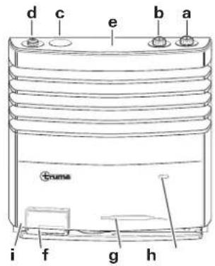
a = Control knob (thermostat)
b = Piezo push ignitor (S 3004 P)
c = Blind cover
d = Integrated control panel for a Truma fan TEB-3
e = Sensor button to switch on the lighting (optional)
f = Automatic ignition device with battery compartment (S 3004)
g = Mica window to observe the flame
h = Thermostat sensor
i = Type plate (remove cover!)

The illustration shows installation on the right. For installation on the left, the parts are arranged on the other side
镜
S 5004 heating system
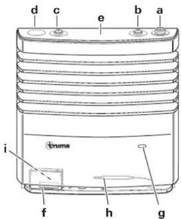
a = Control knob (thermostat)
b = Integrated control panel for a Truma fan TEB-3
c = Integrated control panel for second Truma fan TEB-3
d = Blind cover
e = Sensor button to switch on the lighting (optional)
f = Automatic ignition device with battery compartment
g = Mica window to observe the flame
h = Thermostat sensor
i = Type plate (remove cover!)

The illustration shows installation on the right. For installation on the left, the parts are arranged on the other side
(mirror-image). One or two fans can be mounted. A special installation box can be supplied for the installation of two fans.
Taking into operation
S 3004 P with Piezo push ignitor
- Open gas cylinder and quick-acting valve in the gas supply line.
- Turn the control knob (a) into thermostat position 1 - 5 and push down far as possible. Press the ignitors in quick succession at the same time until the flame burns.
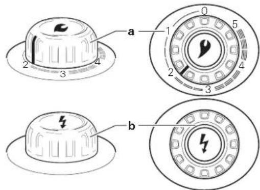
- Hold down the control knob (a) for up to 10 seconds so that the safety pilot responds.
- Watch another 10 seconds through the mica window whether the flame is extinguished by the air in the line (caused by gas cylinder change).

Never re-ignite before waiting another 3 minutes otherwise there is the danger of deflagration! This
also applies if a heating system already in operation goes out and needs to be re-ignited.
If the gas supply line is filled with air, it can take up to two minutes until the gas is ready to burn. Keep the control knob pressed down and keep pressing the ignitor until the flame burns.
- In order to achieve even and quick distribution of warm air and reduction of the surface temperature at the outlet grill for warm air, we recommend that the heating system is operated with the Truma warmer running.

The S 3004 P heating system (with Piezo push ignitor) is constructed so that subsequent installation of an auto ig is possible part no. 30580-01).
S 3004 / S 5004 with auto ignitor
Make sure that a battery is inserted before commissioning for the first time (see „Battery change on auto ignitor“)!
- Open gas cylinder and quick-acting valve in the gas supply line.
- Turn the control knob (a) into thermostat position 1 - 5 and push down far as possible. Ignition takes place automatically (audible ignition) until the flame burns.
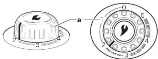
Hold down the control knob for up to 10 seconds so that the safety pilot responds.

Wait min. 3 minutes before re-igniting after a fault, otherwise there is the risk of deflagration!
Should the flame go out during operation, immediate re-ignition takes place within the closing time of the safety pilot (approx. 30 seconds).
If a flame is not produced, the auto ignitor continues to work until "0" is switched on the control knob (a).
If the gas supply line is filled with air, it can take up to two minutes until the gas is ready to burn. Keep the control knob pressed down during this time until the flame burns.
- In order to achieve even and quick distribution of warm air and reduction of the surface temperature at the outlet grill for warm air, we recommend that the heating system is operated with the Truma warmer running.
Operating the fan
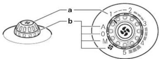
a = Control knob / scale for fan power (1 - 5)
b = Rotary switch / scale for operating modes
A Automatic The electronics regulate the required fan output and limit the speed to the set value.
0 OFF Switch off fan.-
M Manual Set the required fan level.
Booster level Set the fan power to the highest value (for maximum air volume current).
Lighting
The lighting (optional) for the panels is activated by a proximity switch. Touch from above on the middle of the cover. This means that the lighting is switched on for approx. 20 seconds.
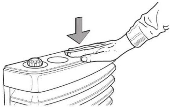
Each time the 12 V voltage supply is produced, the sensor electronics calibrate the lighting. This can take several seconds. Do not touch the cover during calibration.
Room thermostat
An average room temperature of approx. 22^ is achieved with a thermostat setting of approx. 3 without operating the fan. We recommend operation with a fan and a thermostat setting of approx. 4 for comfortable warm air distribution and for reduction of condensation on cold surfaces.
The exact thermostat setting must be established corresponding with the construction type of the vehicle and according to the individual warmth requirement.
The thermostat sensor is on the bottom of the heating system. Please note that the cold draughts caused by refrigerator ventilation, gaps in doors or a high pile carpet can have a negative influence on the thermostat. Such sources of disturbance are to be addressed in all cases otherwise a satisfactory temperature control is not guaranteed.
Switching off
Set the control knob on the heating system to "0" (the auto ignitor is simultaneously switched off).
Switch off fan (set rotary switch to "0").
If the device is not used for a longer period, close the quick-acting valve in the gas supply line and gas cylinder.
Maintenance
Always notify the Truma Service Centre or one of our authorised service partners if problems are encountered (see Truma Service book or www.truma.com).
Despite careful production, the heating system can contain parts with sharp edges, therefore always wear protective gloves for maintenance and cleaning work!
Observe the ESD-regulations! There is a risk of damage to the electronics due to static charge. Only experts may carry out repair work!
Cleaning (only with the device switched off!)
It is recommend to remove the dust that has collected on the heater exchanger, floor plate and on the fan wheel on the Truma warm air system at least once per year at the beginning of the heating season. Carefully clean the fan wheel with a paint brush or small brush.
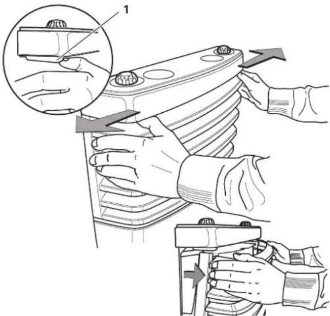
Remove cover
Only remove the cover with the heating switched off and cold.
By simultaneously pressing both closure levers (1) outwards, the cover is unlocked. It can be pivoted out and lifted out of the lower bearings.
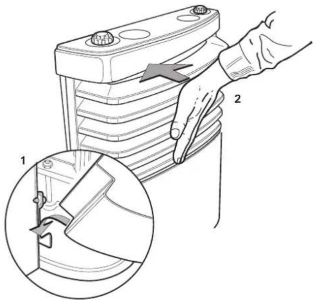
Attach cover
Suspend the cover (1) in the bottom bearing and pivot in (2) until the lock audibly clicks into place. Check the tight fit by pulling.
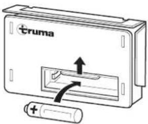
Battery change on the auto ignitor
If ignition sparks cannot be heard when commissioning or only at intervals of more than one second, the battery needs to be replaced.
Only change the battery with the heating system switched off. Insert a new battery before the beginning of each heating season! Dispose of the old battery correctly!
Only use temperature-resistant (+70^) , leak-proof mignon batteries (LR 6, AA, AM 3) (part no. 30030-99200); other batteries can cause function faults!
Remove the cover, slide the battery compartment cover up and change the battery. Pay attention to positive/negative. Close the battery compartment again. Put the cover back on.
Specific information
If the vehicle floor is provide with underbody protection, all heating parts found under the body must be covered so that the spray mist does not lead to functional faults. Remove the covers again after finishing work.
Disposal
Dispose of the unit and the battery in the auto ignitor separately as specified in the administrative regulations of the respective country in which it is used. National regulations and laws (in Germany, for example, the End-of-life Vehicle Regulation) must be observed.
In other countries, the relevant regulations must be observed.
Technical data
(established according to EN 624 or Truma test conditions)
S 3004 / S 3004 P / S 5004
Gas type
Liquid gas (propane / butane)
Operating pressure
30 mbar (see type plate)
Rated thermal output
S 3004/S 3004P:3500W
S 5004:6000W
Gas consumption
S 3004 / S 3004 P: 30 - 280 g/h
S 5004: 60 - 480 g/h
Additional information according to EN 624
S 3004 / S 3004 P: Q_p = 4,0 kW(Hs) ; 290 g/h; C_p1 ; I_p1m
S 5004: Q = 6,8kW (Hs); 490 g/h; C51, I3BP2
Countries of destination
BE, BG, RO, DK, DE, EE, FI, FR, GB, UK, IS, IE, IT, LV, LT, LU
MT, NL, NO, AT, PL, PT, SE, CH, SK, SI, ES, CZ, HU, CY
Operating voltage
1.5 V (automatic ignition device with battery compartment)
Current draw
225 mW (ignite)
Weight
S 3004 / S 3004 P: approx. 10.3 kg (without fan)
S 5004: approx. 17.5kg (without fan)
Dimensions
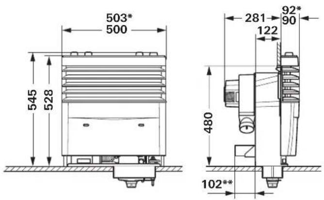
S 3004 / S 3004 P

S 5004
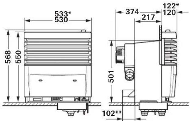
- with chrome decorative strip
** Truma Ultraheat (optional)
Dimensions in mm with tolerance +2mm / - 1mm
The right to effect technical modifications is reserved!
Declaration of conformity
1. Information about the manufacturer
(respectively with and without Ultraheat)
3. Meets the requirements of the following Directives
3.1 Gas Appliances Directive 2009/142/EC
3.2 Heating Appliance Directive UN ECE R122
3.3 Electromagnetic Compatibility 2004/108/EC
3.4 Radio Interference in Vehicles 2009/19/EC, UN ECE R10
3.5 Low Voltage Directive 2006/95/EC
3.6 End-Of-Life Vehicle Directive 2000/53/EC
and bears the type approval numbers E1 10R-036531
S 3004 / S 3004 PE1 122R-000361
S 5004 E1 122R-000362
and the CE symbol with the CE product ident. no.
S 3004 / S 3004 P CE-0085CM0287
S 5004 CE-0085CM0288
4. Basis of the conformity assessment
DVGW, Federal Motor Transport Authority
6. Information and the function of the signatory
Signature: Dr. Andreas Schmoll
Managing Director / Engineering Putzbrunn, 13.09.2011
Manufacturer's terms of warranty
1. Case of warranty
The manufacturer grants a warranty for malfunctions in the appliance which are based on material or production faults. In addition to this, the statutory warranty claims against the seller remain valid.
A claim under warranty shall not pertain
- for parts subject to wear and in cases of natural wear and tear,
- as a result of using components in the units that are not original Truma parts,
- for gas pressure regulation systems as a result of damage by foreign substances (e.g. oils, plasticisers) in the gas,
- as a consequence of failure to respect Truma instructions for installation and use,
- as a consequence of improper handling,
- as a consequence of improper transport packing.
2. Scope of warranty
The warranty is valid for malfunctions as stated under item 1, which occur within 24 months after conclusion of the purchase agreement between the seller and the final consumer. The manufacturers will make good such defects by subsequent fulfilment, i.e. at their discretion either by repair or replacement. In the event of manufacturers providing service under warranty, the term of the warranty shall not recommence anew with regard to the repaired or replaced parts; rather, the old warranty period shall continue to run. More extensive claims, in particular claims for compensatory damages by purchasers or third parties, shall be excluded. This does not affect the rules of the product liability law.
The manufacturer shall bear the cost of employing the Truma customer service for the removal of a malfunction under warranty - in particular transportation costs, travelling expenses, job and material costs, as long as the service is carried out in Germany. The warranty does not cover customer service work in other countries.
Additional costs based on complicated removal and installation conditions of the appliance (e.g. removal of furniture or parts of the vehicle body) do not come under warranty.
3. Raising the case of warranty
The manufacturer's address is:
Truma Geratetechnik GmbH & Co. KG
Wernher-von-Braun-Straße 12
85640 Putzbrunn, Germany
Always notify the Truma Service Centre or one of our authorised service partners if problems are encountered (see Truma Service book or www.truma.com). Please describe you complaint in detail and state the factory number of the device and the purchase date.
In order for the manufacturer to be able to determine whether an incident subject to guarantee has occurred, the end user must, at his own risk, bring or send the device to the manufacturer. If there is damage to heat exchangers, the gas pressure regulator must also be sent back to the factory.
Air conditioners:
To avoid transportation damage, the unit may only be sent to the Truma Service Centre Germany or one of our authorised service partners if agreed beforehand. Otherwise the sender bears the risk for any transportation damage.
Please send all shipment to the factory as freight. In cases under guarantee, the works shall bear the transport costs or the costs of delivery and return. If the damage is deemed not to be a warranty case, the manufacturer shall notify the customer and shall specify repair costs which shall not be borne by the manufacturer; in this case, the customer shall also bear the shipping costs.
Table des matieres
i = plaque signalétique (retirer la façade !)
i = plaque signalétique (retirer la façade !)
a = Bedieningshendel (thermostat)
b = Piezodrukontsteker (S 3004 P)
c = Blind deksel
h = Thermostat sensor
1. Producers stamdata
2. Identification of apparatus
Type /udfərelse:
LPG-varmeovn / S 3004 / S 3004 P / S 5004 (med og Eden Ultraheat)
3. Opfylder kravene i falgende direktiver
3.1 Gasapparatdirektiv 2009/142/EF
3.2 Varmeapparatsdirektiv UN ECE R122
3.3 Elektromagnetisk kompatilitet 2004/108/EF
3.4 Stjdaempning i personbiler 2009/19/EF, UN ECE R10
3.5 Lavspændingsdirektiv 2006/95/EF
3.6 Direktiv 2000/53/EF vedr. gamle koretjer
og bær typegodkendelsesumre E1 10R-036531
S 3004 / S 3004 P E1 122R-000361
S 5004 E1 122R-000362
5. Overvågende organ
GB Always notify the Truma Service Centre or one of our authorised service partners if problems are encountered (see Truma Service book or www.truma.com).
Having the equipment model and the serial number ready (see type plate) will speed up processing.