Square 40 G - Heating WANDERS - Free user manual and instructions
Find the device manual for free Square 40 G WANDERS in PDF.



| Product type | Built-in gas stove |
| Brand | Wanders |
| Model | Square 40 G |
| Category | Heating |
| Power supply | Natural gas or propane |
| Ignition type | Manual with pilot light |
| Remote control | Remote control with timer programmer (4 time slots) |
| Functions | Flame height adjustment, manual/automatic/timer mode, child safety (local control), temperature display in °C or °F |
| Protection | Gas flow safety thermocouple, automatic shut-off after 2 hours without remote signal |
| Batteries | Receiver: 4 LR6/AA batteries (1.5 V) or one 9 V battery; remote: one 9 V alkaline battery |
| Flue duct | Wanders concentric (inner diameter 80 mm, outer diameter 150 mm) |
| Maximum pipeline length | 10 m (excluding wall penetration and outlet), with 90° elbows = 2 m, 45° elbows = 1 m |
| Installation | By certified installer, in accordance with national and local regulations |
| Routine maintenance | External cleaning with damp cloth (unit cold) |
| Annual maintenance | By certified installer: check seals, burner, pilot light, ducts, gaskets, cleaning |
| Log set | Ceramic, exclusively for natural gas, precise placement according to manual |
| Pebble set | For natural gas and propane, do not obstruct the burner |
| Glass | Ceramic, clean with damp cloth and hob cleaner |
| Warranty | 1 year on material and workmanship defects, excluding glass and consequential damages |
| Safety | Do not use without glass, keep distance 1.5 m from combustible materials, do not leave children unattended |
Frequently Asked Questions - Square 40 G WANDERS
User questions about Square 40 G WANDERS
0 question about this device. Answer the ones you know or ask your own.
Ask a new question about this device
Download the instructions for your Heating in PDF format for free! Find your manual Square 40 G - WANDERS and take your electronic device back in hand. On this page are published all the documents necessary for the use of your device. Square 40 G by WANDERS.
USER MANUAL Square 40 G WANDERS
natural_image
Interior sketch of a cozy living room with sofa, fireplace, and TV (no text or symbols)GB Users guide and installation manual 16
Gasregelblok
natural_image
3D diagram of a mechanical device with open door and internal components, showing directional arrows (no text or symbols)
Kinderbeveiliging
natural_image
Black box containing four cylindrical beverage containers with visible branding (no readable text or symbols)natural_image
Close-up of a black remote control device with attached battery and a partially visible card, placed on a metal surface (no text or symbols visible)natural_image
Pure diagram of a room layout with arrows indicating flow or movement, no text or symbols presentnatural_image
3D rendering of a modular kitchen appliance with open and closed doors, showing internal components and mounting brackets (no text or symbols)natural_image
3D CAD model of a mechanical housing or enclosure with internal components and mounting holes (no text or symbols visible)natural_image
3D rendering of a modular electronic enclosure with internal components and mounting brackets (no text or symbols visible)Square Free
natural_image
3D CAD renderings of a mechanical housing assembly, showing front and side views (no text or symbols)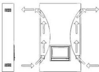
natural_image
Pure diagram of a symmetrical structure with directional arrows, no text or symbols presentHoutset plaatsen

natural_image
Interior view of a dark industrial machine with two white powders on trays (no visible text or symbols)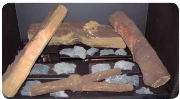
natural_image
Archaeological excavation site showing ancient stone fragments and embedded stones (no visible text or symbols)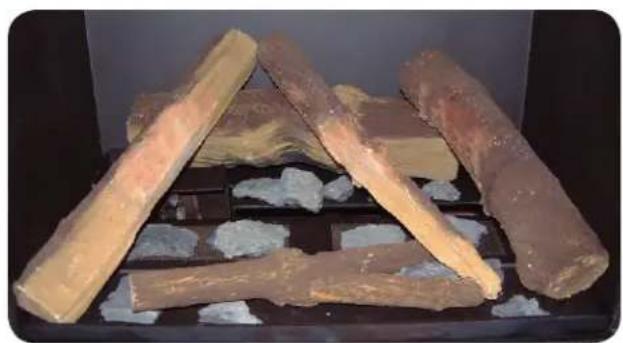
natural_image
Stacked wooden logs on a black tray with white foam, no visible text or symbols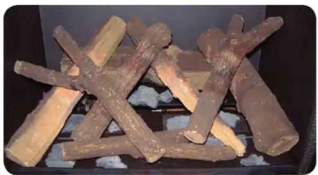
natural_image
Stacked dried plant logs on a stove burner (no text or symbols visible)natural_image
Four white dough balls placed on a perforated metal tray inside a black oven (no text or symbols visible)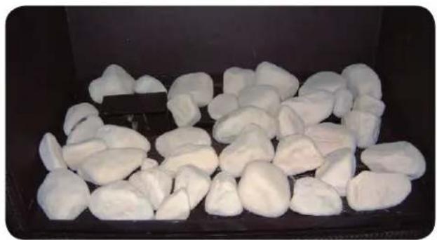
natural_image
Close-up of white, irregularly shaped objects arranged in a dark container (no text or symbols visible)
Lighting the pilot flame manually 18
Arranging the height of the flames 18
Switching off the pilot flame 19
Lighting the hearth for the first time 19
Batteries 20
Setting the remote control handset 20
Setting the time and the date 20
Setting in Fahrenheit or Celsius 20
Setting the desired temperature 21
Checking the set temperature 21
TIMER 21
MAN 21
Maintenance 21
Small maintenance 21
Annual maintenance 21
Safety 22
Possible error messages 22
Guarantee 22
Installation instructions Square 40 Gas 23
Placing 23
Insulation 23
Gas connection 24
Placing of the concentric flue system 24
Placing possibilities of the flue system 24
Wall outlet 25
Roof outlet 25
First install the flue system, and then place the gas unit 25
Opening the door 25
Removing the flue collar 26
Placing a pipe closer 26
Installation 27
Square (insert) 27
Square Wall 27
Square Free 27
Placing the logs or pebbles 28
Electrical scheme 58
Technical drawings 59
Gas details 62
Notes 63
Dear Client,
Congratulations on your new WANDERS gas fireplace. It will be a comfortable source of heat to enjoy for many years on end.
Your gas hearth is fitted with a so-called closed system double-walled flue. The flue gases are directly discharged through the inner flue. The outer pipe extracts fresh air which produces beautiful and evenly burning flames. In principle, your gas unit can be installed in all kinds of spaces, even in rooms without any ventilation or with mechanical ventilation.
When designing this fireplace we took particular care of the ease of use, the safety and the design. Your gas unit is developed and produced at our own factory in Netterden (the Netherlands) and is for the greater part handmade. Only the best materials are used for the construction and comply with current international standards. This will guarantee that your hearth has a long life.
The first part of this user's guide gives you tips and directions about how to use your gas fireplace correctly and safely. The second part of the manual contains the installation instructions and the technical specifications of the gas unit. They are of particular importance to the installer.
We advise you to read this manual thoroughly before using your new gas fireplace and to keep the manual in a handy place. Your installer may need the manual for the yearly maintenance of your fireplace.
We wish you much warmth with your new fireplace!
The WANDERS team

• Do not use the appliance without glass.
- Do not put flammable substances on the ceramic wood log set
- Do not place highly flammable materials like nylon clothes of flammable fluids in the neighbourhood of the appliance.
- This appliance is not meant for operation by persons (including children) with limited physical or intellectual faculties, or by persons who are unfamiliar with the operation of gas appliances. Always ensure that they are supervised when near the appliance.
• Use a fire-screen to avoid burning and to protect the above-mentioned children and persons.
- The appliance must be mounted and connected as a 'closed unit' by an acknowledge installer in accordance with the installation instructions and national and currently applicable local regulations
General information
It is common practice for the dealer where you purchased your gas unit to take also care of installing it and connecting it to the mains. If this is not the case, please ensure that the installation is done by a certified installer. Connecting gas devices by unqualified persons is prohibited, in which case we cannot give any guarantee that your gas hearth is functioning properly.
Ready for use
After connecting your Wanders gas unit to the mains and making the necessary adjustments, the hearth is ready for use. The pilot flame must be ignited manually.

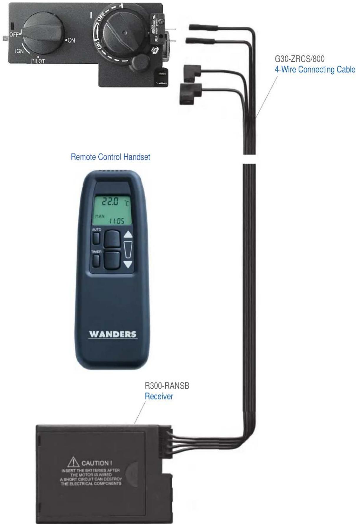
Receiver
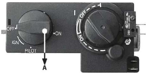
Gas governor (A)
Lighting the pilot flame manually
-
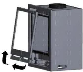
Remove the front frame by pulling it towards you and then lifting it as shown on the image.
-
You're now able to see the controls as shown on the images above.
-
Turn the ignition knob (A) until it stops (spark symbol / IGN), then press the knob and wait a few seconds.
-
While keeping the knob pressed, turn the knob to the left until you hear a click.
-
Look through the glass pane to see whether the pilot flame is burning. If the pilot flame is not ignited, repeat steps 3 and 4.
-
If the pilot flame is burning, keep the ignition knob pressed for some time. When you release the knob after 30 seconds, the pilot flame must stay alight. If it doesn't, wait for 5 minutes before trying to light the pilot flame again.
-
If the pilot flame stays alight, turn the knob anticlockwise till the symbol of the large flame. Now you can close the flap and regulate the height of the flames with the remote handset.
natural_image
3D rendering of a mechanical housing with open door and internal components, showing directional arrows (no text or symbols)
Child-proof safety lock
If you turn the ignition knob to the symbol of the small flame, the remote control is put out of action while the pilot flame will stay alight.
Arranging the height of the flames
Point the remote control handset towards the gas unit. The hearth will burn higher when pressing the ▲ button. The hearth will burn slower when pressing the ▼ button. When you keep pressing the ▼ the hearth will switch to the pilot flame position. You can also put the hearth on the pilot flame position manually by turning the ignition knob (A) until the minimum is reached (small flame / PILOT).
When you press both buttons, you will see the 'transmit' signal top left on the display. The hearth has reached its highest or lowest position when the LED of the receiver starts blinking.
Switching off the pilot flame
The pilot flame is switched off manually. Remove the frame, gently press the ignition knob (A) and then turn it towards the dot / OFF indication.
Lighting the hearth for the first time

When you light your gas unit for the first time, the hearth must 'anneal'. The unit has a heat resistant lacquer which must still burn in. Though this may give an unpleasant smell, it is otherwise harmless. It is advisable to turn onto high for about three hours while airing the room well.

Discolouration of walls, ceilings and grates
After lighting your heath the walls, ceilings and grates may show some discolouration. This is caused by the dust particles that burn in the convection cover. This is a natural process for which WANDERS cannot be held responsible. To minimize the discolouring we refer to the advice given for atmospheric hearths. Your installer can give you more information about this.
Some deposit may form on the ceramic glass of the door of the hearth. You can easily remove this deposit with a damp cloth and if necessary some cleansing agent for ceramic rings when the glass has cooled down. On page 25 you'll find a description on how to open the door and remove the glass.

Avoid finger marks
Avoid leaving any finger marks on the glass after closing the door. Finger marks leave stains that burn in the glass and cannot be removed later.
When you light your fireplace for the first time, the unit calculates how much time is needed to reach the pre-set temperature. Your hearth will now select the most efficient way to heat the room.

Ensure that the logs are not placed in front of the pilot flame. The gas must be able to stream freely to the main burner. The main burner is located underneath the log set. See page 20 for placing the log set properly.
It is advisable to keep the pilot flame burning in heating seasons to prevent condensation and possible calcification on the inside of the door.

Newly-built house or recently renovated?
It is advisable to wait six weeks before lighting the hearth in a newly-built house that has recently been delivered, or a space or room that has recently been drastically renovated. The walls and ceilings still contain gases, softeners and moist from plasterwork or paint. The warm air-streams may discolour the dust particles in the space which may stick to walls and ceilings. When the moist in the walls and ceilings warm up, this may also cause yellowish stains.
Batteries
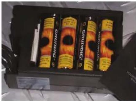
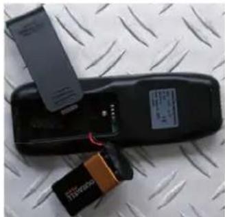
Your gas hearth is delivered with batteries in the receiver. It is advisable to place new batteries in the receiver and the remote handset when installing your gas unit. The receiver in the hearth works on 4 batteries of 1.5 V (type LR6 or AA) or 1 x 9 V alkaline. The remote handset is powered by a 9 V alkaline block battery. The batteries will last for about one year.
When are the batteries due for replacement?
- The batteries of the receiver are due for replacement if you see that the engine works with increased difficulty.
- The battery of the remote control handset is due for replacement when the display shows BATT in the top right hand corner.
natural_image
Black box containing four cylindrical beer bottles with flame patterns, no visible text or symbols on the packaging itself.Replacing the batteries of the receiver
natural_image
Black remote control device with attached electronic components and a metallic strip, placed on a metal surface (no visible text or symbols)Replacing the batteries in the remote control
Setting the remote control handset
Setting the remote control of your gas unit is simple. Once you have done it you can operate your hearth in less than no time. Your remote can even pre-set four time schedules for the desired temperatures.
It is advisable to switch off your hearth when you pre-set the remote to avoid accidentally changing the temperature of your unit.
If your Square hearth has not received a signal from the remote control for two hours, the unit switches automatically back to the pilot flame setting. The pilot flame will burn continuously.

If you switch off the pilot light after lighting your hearth, you must wait at least five minutes before lighting the hearth again.
Setting the time and the date
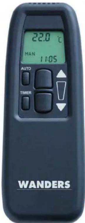
After placing the batteries, or by pressing the buttons AUTO and TIMER simultaneously, the display will start flashing. With the ▲ button you select the hour. With the ▼ button you set the minutes. Wait for a few seconds, or press the TIMER button to save the pre-set time.
Setting in Fahrenheit or Celsius
The display starts blinking after placing the batteries, or after simultaneously
pressing the buttons AUTO and TIMER. When the display is still blinking, you can switch from Fahrenheit / 12-hour indication to Celsius / 24-hour indication. The indication will switch when pressing the AUTO button. The display will switch automatically to manual operation after some time
Setting the desired temperature
Press and hold the AUTO button until the TEMP indication blinks. You can set a higher temperature with the ▲ button and a lower temperature with the ▼ button. Then wait a few seconds, or press the AUTO button to switch to the automatic modus.
Checking the set temperature
Briefly press the AUTO button. The display briefly shows the pre-set temperature and then displays the room temperature.
TIMER
You can pre-set a total of four time-settings. When you link up all four time-settings, you can be sure of a comfortable room temperature at all times.
Press and hold the TIMER button until the indication P1<◇> blinks. With the ▲ and ▼ buttons you can set respectively the hours and the minutes. By briefly pressing the TIMER button you can browse through the timer programme P1<◇>, P1< >, P2<◇> and P2< >. Here is an example of a possible pre-setting.
P1<◇>-temp: 07:30 - 08:30 the pre-set temperature
P1< >-temp: 08:30 - 17:00 off
P2<◇>-temp: 17:00 - 23:00 the pre-set temperature
P2< >-temp: 23:00 - 07:30 off
The TIMER function works only when the pilot flame is on. If the TIMER mode is switched on, the temperature control will be the same as in the AUTO position. You can switch off the TIMER mode with the ▲ and ▼ buttons. The remote control will automatically switch to the MAN function.
MAN
When the display shows the MAN position you can manually turn the hearth higher ▲ and lower ▼ by using the big buttons. When you press and hold the ▼ button the hearth will go to its lowest position: the pilot flame. When you keep these buttons pressed, you will see the 'transmit' symbol top left in the display. You will know when the hearth has reached its highest or lowest position when the LED of the receiver starts blinking.
Maintenance
Small maintenance
You can clean the outside of the hearth with a damp cloth that doesn't give off fluff. Only clean the outside when the hearth is cold. If some coffee is spilled on the unit when it is burning, turn the hearth off immediately. When the hearth has cooled off completely, you can remove any stains with a damp cloth

Do not use any aggressive cleansing agents or abrasives and do not use stove polish.
Annual maintenance
Your gas hearth needs to be checked and maintained by a certified installer at least once a year. He will check and, if necessary, clean the following components:
• The air-tightness of the exhaust pipes for gas and fumes and the pipes for supplying combustion air.
- The proper functioning of the gas governor, the thermocouple interrupter (a safety measure against unexpected outflow of gas) and the ignition of the main burner.
- The entire pipe system, including the exterior wall or roof duct and the external terminal.
• Inspection of possible wear and tear of the sealing of the doors and glass panes.
- The following components will be cleaned: the main burner, the pilot light, the flue tube and the supply of combustion air. Any dust collected in the hearth can be removed with a vacuum cleaner.
Safety
A WANDERS source of heat is more than just a stove in your room; the flue and the roof duct are also part of the heating system. Only when your gas hearth is installed with the concentric flue designed by WANDERS can we guarantee that your hearth is burning safely.
Every gas hearth by WANDERS is installed with a thermocouple interrupter. This will prevent unexpected gas flow if the pilot light has gone out.
Here are some recommendations for safely using your gas hearth:
- Only use your gas hearth when the door is properly closed. When the door is open, or the glass damaged, you must not use the fireplace.
- Prevent small children or the infirm from getting too close to a burning stove and do not leave them alone in the room when the fireplace is ignited. You could use a fire-screen.
- Turn the ignition knob all the way to the symbol of the small flame to deactivate the remote control while the pilot flame stays on. This is to ensure that nobody can accidentally change the temperature of your hearth.
• Never allow children to play with the remote handset. - Do not pour or put any combustible liquids and materials on the log set, as it may damage the unit beyond repair.
- Do not place any combustible materials, such as curtains, close to the fireplace. A minimum distance of 1.5 meters is required.
• The fireplace must be repaired with original parts only, and by a certified installer.
• If for any reason the pilot light goes out, you must wait 5 minutes before igniting the hearth again.
Possible error messages
If your hearth does not function as planned please contact your gas hearth dealer or a certified installer. If the pilot light does not ignite, you can take the following steps.
• Check whether the gas supply is open. If you cannot find the gas supply please contact your installer.
- There may be some air in the pilot feed line. Wait for 5 minutes and light the hearth again. If this does not help please contact a certified installer.
Guarantee
WANDERS Metaalwerken B.V. in Netterden, the Netherlands, gives a one-year guarantee after the purchase date, provided that the fireplace is properly installed and used in accordance with the instructions in the manual.
The guarantee includes all defects which can be reduced to flaws in material and construction, in which case you will receive the new parts free of charge. Labour costs or other expenses are not covered by the guarantee. You can send defect parts (carriage paid) to WANDERS Metaalproducten B.V., Amtweg 4, 7077 AL in Netterden [The Netherlands].
The guarantee does not include: failure due to improper use; non-compliance with the installation and operating instructions; installation by a non-certified installer; negligence of the apparatus and converting the fireplace to be fired with another kind of gas.
Wanders cannot be held responsible for any cracks in stuccoed walls or discolouration of walls, ceilings and/or grates after burning the fireplace. Discolouration is caused by the burning of dust particles in the convection cover. To reduce the chance of cracks in stucco and to minimize discolouration we refer to the advice given for decorative hearths. Your installer can give you more information.

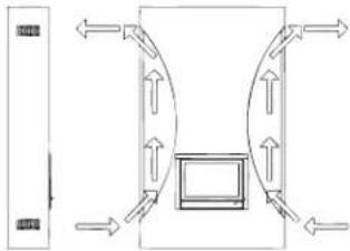
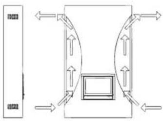
WANDERS recommends adding extra air inlets with all inserts and built-in stoves
natural_image
Pure diagram of a room layout with directional arrows and a central monitor (no text or symbols)Any complaints will be dealt with after the sales firm, the installer or the gas company filed a complaint and sent a copy of the purchase receipt with purchase date. Any repairs do not entitle you to extend the guarantee term. All consequential damages or loss are excluded.
Installation instructions Square 40 Gas
Your gas hearth must only be installed by a certified installer and only in combination with the WANDERS concentric pipe system. Only then will the hearth be approved according to the European CE standards for gas appliances. We will not give any guarantees if the gas hearth is fitted and/or installed in an incomplete or improper manner. The pipe system consists of an inner pipe with a diameter of 100 millimetres and an outer pipe with a diameter of 150 millimetres.
The appliance may only be installed and fitted by a certified installer in accordance with current universal gas piping regulations and according to the installation instructions mentioned below. Furthermore, the national and local rules and regulations on placing and using closed gas appliances shall be applicable. Only certified installers are authorized to change the pre-set values (in line with the regulations) or make any other adjustments.

Before installing the appliance, the installer must check whether the information on the type tag of the fireplace corresponds with the gas type and gas pressure to which the appliance is connected. If it does not match, it is not allowed to connect the gas unit.
Placing
The gas hearth is designed to be build in exciting construction and newly build constructions. All materials used in the area of the hearth need to be heat and fire resistant. The gas hearth must be placed on a floor that is solid enough to hold it.
The gas hearth can be placed in a crack-free and/or mechanically ventilated home without difficulty. There is no need for extra ventilation for combustion, or for a smoke and fire vent. Waste gases are discharged by natural draught via the inner pipe into the open. The oxygen needed for burning the fire is supplied from the space between the pipes. This is the reason that no insulation must be placed between the inner and the outer pipe.
Insulation
Due to the high temperatures of the exterior walls (up to approximately 150 °C or 300 °F) it is prohibited to have any combustible materials close to the channel system. The entire concentric pipe system should be encased (heat resistant) from the place where it is out of sight up to the outlet in the exterior wall. Ventilate the encased concentric pipe system by placing a grid near the floor and the ceiling on every floor. Use universal wall clips with a diameter of 150 mm for anchoring the concentric pipe system.
If an existing chimney is used, first make sure whether the chimney is sufficiently insulated and with sufficient diameter to accommodate the concentric pipe system. If the chimney was previously used as a wood-burning or coal-fired stove, the chimney must first be professionally cleaned. You must use special WANDERS connecting sets for connecting a gas hearth to an existing chimney.
Gas connection
• Use a feed pipe with an approved G3/8" stop cock with coupling.
• De-aerate the supply pipe before fi tting and fastening the appliance.
- Avoid all tension on the operating valve and pipes to avoid gas leakage.
• Check if the connection is gastight.
Placing of the concentric fl ue system
The concentric channel system consists of three parts: the channels itself, the transit through the roof or through a wall and the outflow. The diameter for the flue pipes of the Square is 100/150 mm.
Instructions for placing the outlet
The outflow of the pipe system can be placed on top of the roof or against the side wall of the house.
Roof outlet
When placing the outflow on top of the roof, make sure that there is a distance of at least 50 cm between the outflow and the edges of the roof, with the exception of a possible existing ridge. You must also take the place of the outflow into account in relation to the existing ventilation openings, movable windows and combustion air supply provisions. Please consult the national and local requirements.
Wall outlet
When placing the outflow into the side wall, make sure that there is distance of at least 50 cm between the outflow and the corners of the building, eaves, gutters, balconies and etcetera. You need not have this distance when the outflow runs through to at least the front of the overhanging part.

You must also take the place of the outflow into account in relation to the existing ventilation openings, movable windows and combustion air supply provisions. Please consult the national and local requirements.
Placing possibilities of the fl ue system
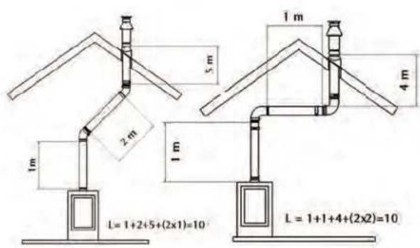
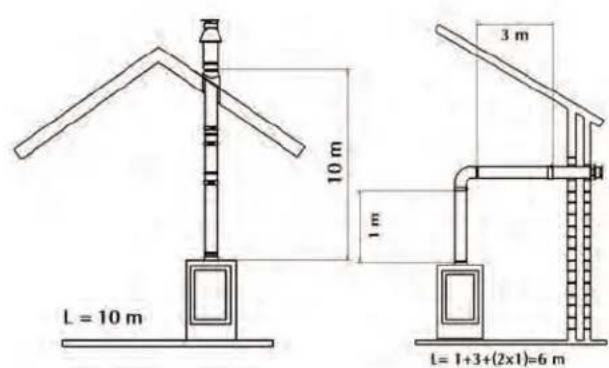
The total length of the pipe system must never be more than 10 metres excluding the passage through the wall and the outflow. A 90° square angle counts as a length of 2 metres. A 45° turn counts as a length of 1 metre.
For the combined flue tube and combustion air supply you must apply one of the shown placing possibilities of the WANDERS concentric pipe systems: with wall duct, with roof duct or with roof duct with bend.
Make your choice from the installation possibilities. Place the first meter of the concentric pipe on the counterpart on the appliance. You will know that you placed it properly if you can see the blue rubber seal ring when looking from above. Keep a distance of at least 5 cm between the inner side of the concentric pipe and the wall or the ceiling.
Pay special attention to proper installing when, due to circumstances, a part of the double-walled pipe system must be built in.
Wall outlet
• Always allow one metre vertical before passing through the outer wall.
• The maximum length of the horizontal placed pipes is 3 meters.
• Determine the location of the gas unit and the exterior wall duct.
• Make an opening of ∅ 155 mm for the wall duct.
- Connect the wall duct with a curve to the mouth of the appliance. Push them firmly together and place the clip bindings. The blue rubber ring ensures sufficient sealing of the discharge system of the waste gas.
- If the appliance is placed more than 1 metre from the wall, place the vertical one-metre pipe first on the appliance, then place the curved part, then the exterior wall duct, and then make them gastight.
Roof outlet
You can place the outflow anywhere on the roof, if necessary with a bend to the ridge of the roof. The roof duct is supplied with a universally adjustable roof tile for a tilted roof, or with an adhesive plate for a flat roof.
• Determine the location of the gas unit and the outflow to the roof.
• Make an opening of ∅ 155 mm for the roof duct.
- Connect the pipes vertically to the mouth of the appliance. Push them firmly together and place the clip bindings.
- Determine the length of the pipes needed and make sure that the transfer tile or the universal roof tile is well fitted to the roof.
- Saw the outer pipe off to measure, and connect the concentric pipes to the roof duct.
First install the flue system, and then place the gas unit
You may also fit the concentric pipe system before placing the gas unit, but then you must the connection to the gas unit with a pipe that can be shifted.
Opening the door
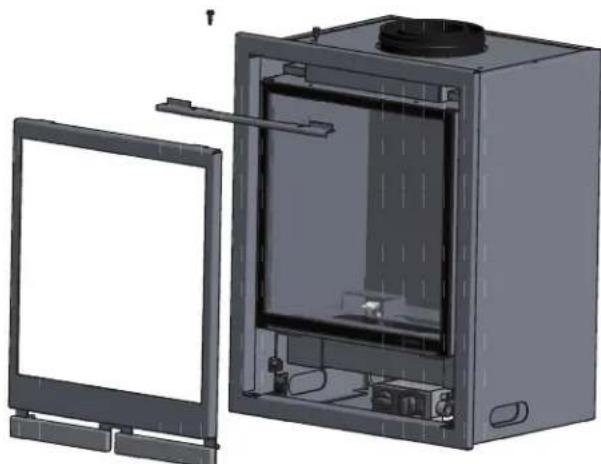
You can open the door by lifting the frame and unscrewing the two 8mm screws and remove the glass pane and the glass.
natural_image
3D rendering of a modular device with an open chamber and a blank screen on the left (no text or symbols visible)Removing the flue collar
First, remove the insert plate from the bottom (A)
Remove the rear wall (B)
Remove the tube connection parts (C and D)
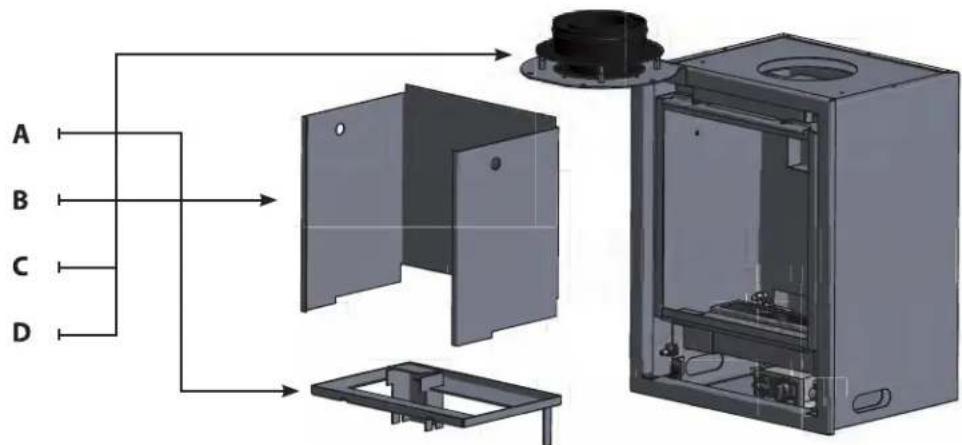
Placing a pipe closer
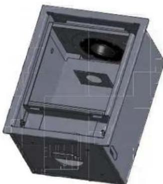
Depending on the total length of the concentric flue system (100/150 mm) and the choice of outlet it's possible a pipe closer needs to placed. The diameter of these pipe closers are ∅40, ∅50 and ∅70 mm. Following the instructions below the closer can be connected to the flue collar inside the combustion chamber as shown on the illustration.
The standard outlet width is 100 mm
natural_image
3D CAD model of a mechanical housing or enclosure with internal components and mounting holes (no visible text or symbols)
Make sure the pipe closer is installed correctly. Installation in the wrong situations, or the in the wrong way may cause malfunctioning of the appliance.
For natural gas:
With 1 metre vertical and wall duct of ∅ 70 mm
With 1 metre vertical and 1,2 or 3 metres horizontal: no pipe closer
With a roof duct without bend you must place:
• A pipe closer of ∅ 50 mm from 2 to 4 metres
• A pipe closer of ∅ 40 mm from 5 to 10 metres
Place the pipe closer by screwing it on the inside below the mouth of the pipe. See the illustration.
For propane
With a wall duct: no pipe closer needed.
With a roof duct without bend you must place:
• A pipe closer of ∅ 50 mm from 2 to 4 metres
• A pipe closer of ∅ 40 mm from 5 to 10 metres
Place the pipe closer by screwing it on the inside below the mouth of the pipe. See the illustration.
Installation
Square (insert)
WANDERS recommends adding extra air inlets with all built-in stoves.
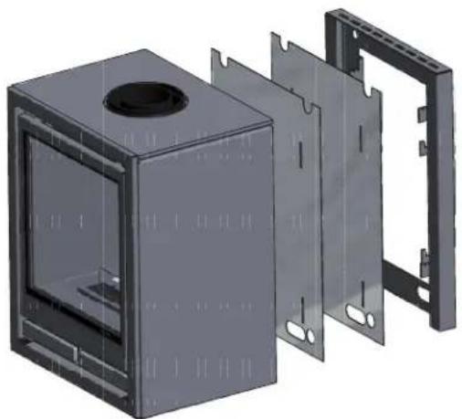
To install the insert model of the Square one needs to remove the 4 attached strips on each corner.
- To remove the strips please unscrew the three screws which hold the strip to the stove (4 strips = 12 screws in total).
- Remove the strips
- Place the screws back in their initial position on the stove.
natural_image
Pure diagram of a room layout with directional arrows and a central monitor (no text or symbols)Square Wall
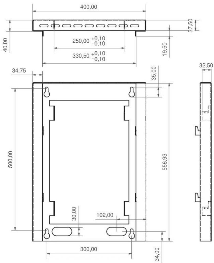
Let a piece of gas pipe ( 12 mm) come from the wall. Attach the provided flexible tube to the gas pipe. Then mount the suspension bracket and the hearth as shown in the illustration below. Please read the rest of this chapter for making the connection to the gas pipe. The technical illustration of the suspension bracket is given on page 60.
natural_image
3D rendering of a modular electronic enclosure with internal compartments and mounting holes (no text or symbols)Square Free
Let a piece of gas pipe (∅ 12 mm) come from the wall. Attach the provided flexible tube to the gas pipe. Then fit the base to the hearth with the 4 screw bolts and push the whole unit towards the gas tube. Please read the rest of this chapter for making the connection to the gas pipe.
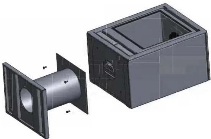
natural_image
3D CAD renderings of a mechanical housing and casing assembly (no text or symbols visible)Placing the logs or pebbles

To avoid any problems, the layout of the logs needs to be exactly as shown on the images
Placing the ceramic lumber set (only for natural gas)
- Place some pieces of ceramic bark exactly as shown in the illustrations. Start with four pieces of bark on the burner but do not block the outflow passage of the pilot.
- Place the ceramic logs exactly as shown in the illustrations. This will give regular flames and prevents soot build-up.
- Place the rest of the bark in the empty spaces around the logs. Do not place them on the burner.

Be sure not to touch the cleaned glass with your fingers when you replace the pane. Finger marks burn in the glass.
Do not forget to replace the door correctly and close it before lighting the hearth.
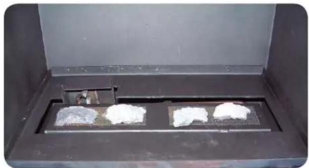
natural_image
Interior view of a dark industrial furnace with two white powders on a tray, no visible text or symbols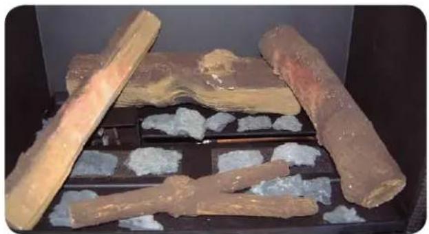
natural_image
Stacked stone and mineral samples in a dark container (no visible text or symbols)
natural_image
Stacked wooden logs on a black tray with white gravel, no visible text or symbols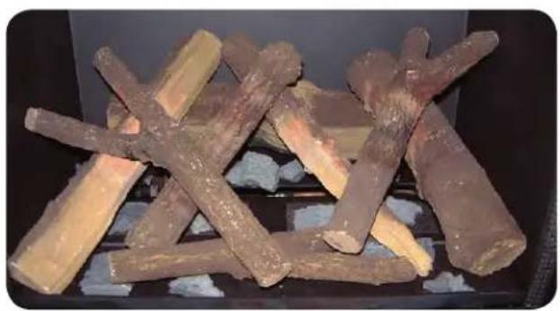
natural_image
Stacked brown wood logs on a stove burner, no visible text or symbolsPlacing the ceramic pebbles (available for natural gas and propane)
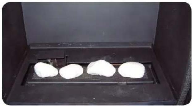
• First put four stones on the burner (see illustration).
• Make sure that the outflow passage in front of the burner is not blocked.
• Then fill up the rest of the bottom with the stones (see the illustration).
• Make sure that the outflow passage in front of the burner is not blocked.

Be sure not to touch the cleaned glass with your fingers when you replace the pane. Finger marks burn in the glass.
Do not forget to replace the door correctly and close it before lighting the hearth.
natural_image
Four white dough balls placed inside a black incubator (no text or symbols visible)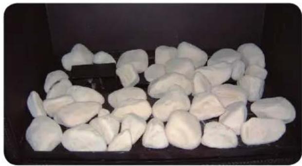
natural_image
Close-up of white, irregularly shaped objects arranged in a dark container (no text or symbols visible)
Make sure there is no log or stone in front of the pilot as this may prevent the main burner from ignition whereby unburned gas may accumulate in the stove. If this happens, you must extinguish the pilot and notify your installer.
You must not add extra ceramic (wood) logs or any other material to the log set. The usage of grains is prohibited (LPG). The stove may not work properly and become damaged beyond repair. Ceramic log sets may be replaced only by the same kind of WANDERS logs.
Installation 32
Prêt à l'emploi 32
natural_image
3D rendering of a mechanical cabinet with open door and internal components, showing directional arrows (no text or symbols)natural_image
Black box containing four labeled cylindrical beer bottles with flame patterns, placed on a white surface (no visible text or symbols)natural_image
Close-up of a black handheld electronic device with a metallic clip and attached battery, placed on a metal surface (no visible text or symbols)natural_image
3D rendering of a modular kitchen appliance with open door and internal compartments (no text or symbols visible)natural_image
3D CAD model of a mechanical housing or enclosure with internal components and mounting holes (no text or symbols visible)
natural_image
Pure diagram of a symmetrical structure with directional arrows, no text or symbols presentSquare Wall
natural_image
3D rendering of a modular electronic enclosure with mounting holes and internal compartments (no text or symbols)Square Free
natural_image
3D CAD renderings of a mechanical housing and casing assembly (no text or symbols visible)Bûches en céramique
natural_image
Interior view of a laboratory or industrial chamber with two white powders on trays, no visible text or symbols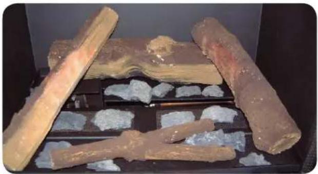
natural_image
Archaeological excavation site with large stone fragments and scattered white stones (no visible text or symbols)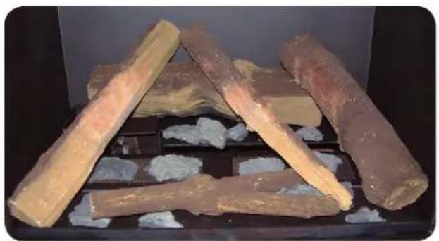
natural_image
Stacked wooden logs on a black tray with white foam, no visible text or symbols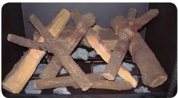
natural_image
Stacked wood logs in a black stove (no visible text or symbols)natural_image
Four white dough balls arranged in a row inside a black incubator (no text or symbols visible)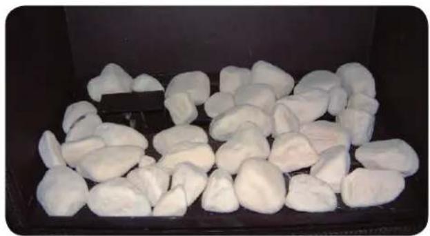
natural_image
Close-up of white, irregularly shaped objects arranged in a dark container (no text or symbols visible)
Gasreglerblock (A)
natural_image
3D rendering of a mechanical cabinet with open door and internal components, showing no text or symbols
Kinderschutz
natural_image
Black cylindrical container with four labeled 'CHUINDIC' branding, showing flame-like patterns inside (no readable text or symbols)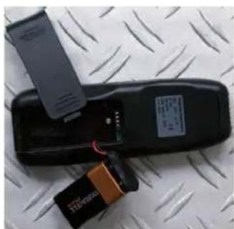
natural_image
Black electronic device with attached power strip and battery, placed on a metal surface (no visible text or symbols)natural_image
3D rendering of a modular kitchen appliance with open and closed casing (no text or symbols visible)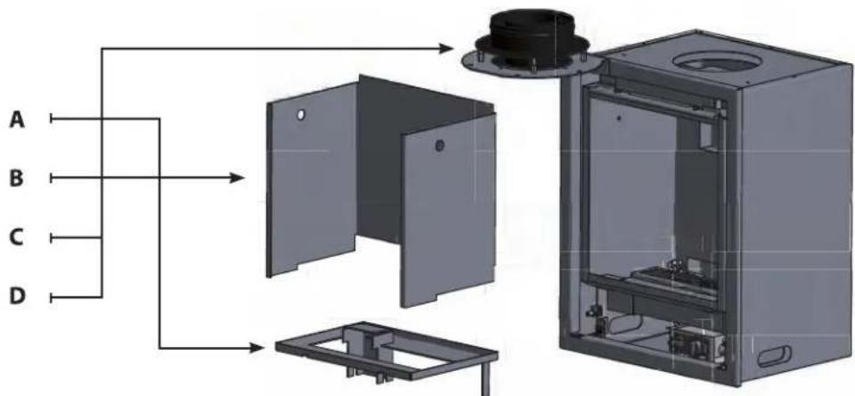
natural_image
3D CAD model of a mechanical housing or enclosure with internal components and mounting holes (no text or symbols visible)
natural_image
Pure diagram of a room layout with directional arrows and a central monitor (no text or symbols)Square Wall
natural_image
3D rendering of a modular metal enclosure with mounting holes and internal compartments (no text or symbols)Square Free
natural_image
3D CAD renderings of a mechanical housing assembly, showing front and side views (no text or symbols)Holzsets einlegen

natural_image
Interior view of a laboratory or industrial chamber with two white powders on trays, no visible text or symbols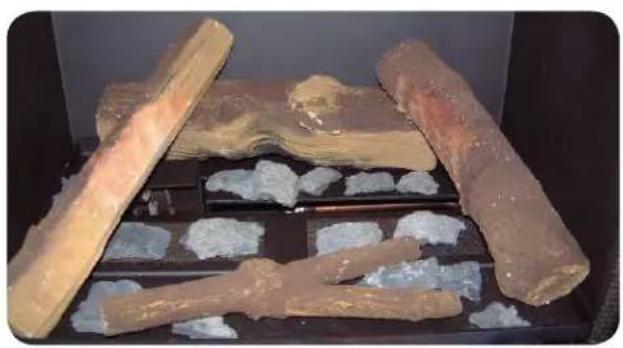
natural_image
Stacked stone and mineral samples in a storage tray, no visible text or symbols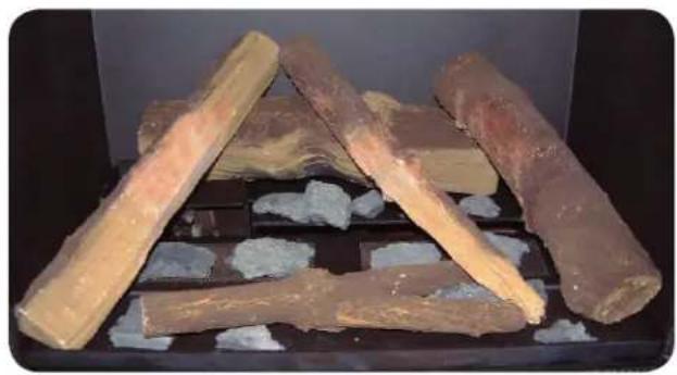
natural_image
Stacked cylindrical food items on a black tray, possibly baked goods or herbs, with no visible text or symbols.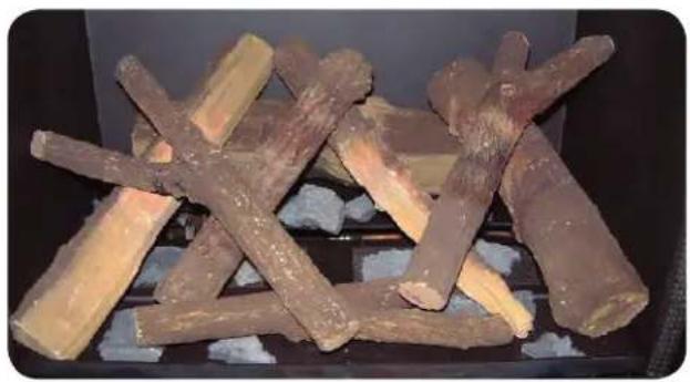
natural_image
Stacked brown wood logs on a stove burner, no visible text or symbols
natural_image
Solid red vertical rectangle with no text, symbols, or patternsnatural_image
Four white, irregularly shaped objects placed inside a black industrial stove (no visible text or symbols)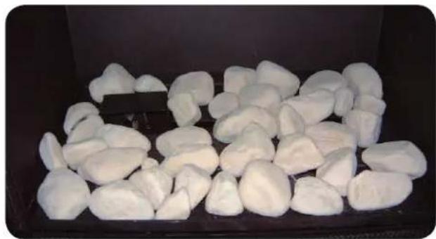
natural_image
Close-up of white, irregularly shaped objects arranged in a dark container (no text or symbols visible)
GV34 Valve with Motor
natural_image
Exterior view of a gray rectangular container with a black top and side dimension label (582,50), no readable text or symbols beyond the measurement.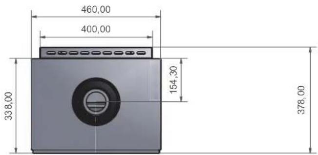
Square 40 Wall
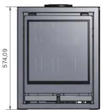
natural_image
Technical diagram of a rectangular device with internal components and dimension label (574,09), no readable text or symbols beyond the dimension line.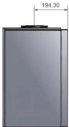
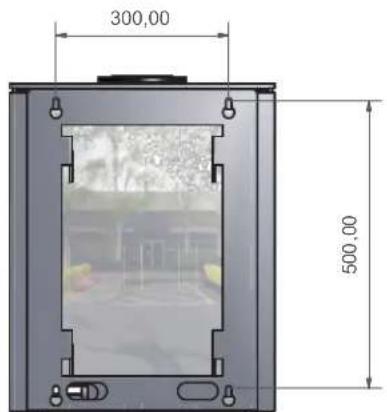
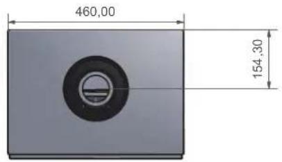
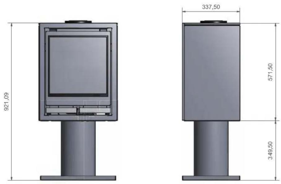
Square 40 Free
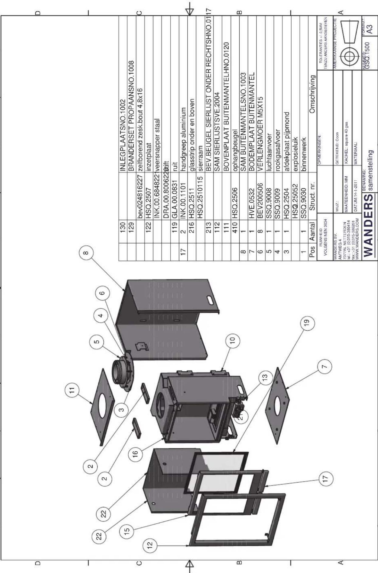
Before installing the appliance, the installer must check whether the information on the type tag of the fireplace corresponds with the gas type and gas pressure to which the appliance is connected. If it does not match, it is not allowed to connect the gas unit.
/// please enclose copy of proof of purchase
The guarantee includes all defects which can be reduced to flaws in material and construction, in which case you will receive the new parts free of charge. Labour costs or other expenses are not covered by the guarantee. You can send defect parts (shipping paid) to WANDERS Metaalproducten B.V., Amtweg 4, 7077 AL in Netterden [The Netherlands].
Before installing your stove you must check if there is any visible damage to the unit. If there is, do not accept the unit and contact your supplier.
The guarantee does not include: the glass, failure due to improper use; non-compliance with the national regulations and enclosed installation and operating instructions; installation by an installer of dealer who is not acknowledged by WANDERS, negligence of the unit and change of owner. The guarantee is also disclaimed when a wrong fuel is used.
WANDERS disclaims responsibility for any cracks in stuccoed walls or discolouration of walls, ceilings and/or grates after burning the fireplace. Discolouration can be caused when dust particles burn in the convection cover. To minimize the chance of cracks in stucco and discolouration we refer to the advice given for decorative hearths. Your installer can give you more information.
Any complaints will be dealt with after the sales firm, the installer has filed a complaint and sent a copy of the purchase receipt with purchase date. Any repairs do not entitle you to extend the guarantee term.
All consequential damages or loss are excluded.

- Kinderbeveiliging
- Square Free
- Houtset plaatsen
- Lighting the hearth for the first time 19
- Batteries 20
- Setting the remote control handset 20
- Maintenance 21
- Safety 22
- Possible error messages 22
- Guarantee 22
- Installation instructions Square 40 Gas 23
- Gas connection 24
- Placing of the concentric flue system 24
- Placing possibilities of the flue system 24
- Opening the door 25
- Removing the flue collar 26
- Placing a pipe closer 26
- Installation 27
- Placing the logs or pebbles 28
- Electrical scheme 58
- Technical drawings 59
- Gas details 62
- Notes 63
- General information
- Ready for use
- Lighting the pilot flame manually
- Child-proof safety lock
- Arranging the height of the flames
- Switching off the pilot flame
- Lighting the hearth for the first time
- Discolouration of walls, ceilings and grates
- Avoid finger marks
- Newly-built house or recently renovated?
- Batteries
- When are the batteries due for replacement?
- Setting the remote control handset
- Setting the time and the date
- Setting in Fahrenheit or Celsius
- Setting the desired temperature
- Checking the set temperature
- TIMER
- MAN
- Maintenance
- Small maintenance
- Annual maintenance
- Safety
- Possible error messages
- Guarantee
- Installation instructions Square 40 Gas
- Placing
- Insulation
- Gas connection
- Placing of the concentric fl ue system
- Roof outlet
- Wall outlet
- Placing possibilities of the fl ue system
- First install the flue system, and then place the gas unit
- Opening the door
- Removing the flue collar
- Placing a pipe closer
- For natural gas:
- For propane
- Installation
- Square (insert)
- Square Wall
- Placing the logs or pebbles
- Placing the ceramic lumber set (only for natural gas)
- Placing the ceramic pebbles (available for natural gas and propane)
- Installation 32
- Prêt à l'emploi 32
- Bûches en céramique
- Kinderschutz
- Holzsets einlegen
Brand : WANDERS
Model : Square 40 G
Category : Heating