
SMO210TRP - Soundbar SAMSUNG - Free user manual and instructions
Find the device manual for free SMO210TRP SAMSUNG in PDF.
| Product Type | Triplex security monitor (Live/Playback/Triplex) with 21" CRT display |
| Brand | Samsung |
| Model | SMO210TRP |
| Dimensions (W × D × H) | 520 × 509 × 486 mm |
| Net Weight | 28 kg |
| Weight with packaging | 32.5 kg |
| Power Supply | AC 100-240 V, 50/60 Hz |
| Power Consumption | See label on the back of the unit |
| Video System | PAL only |
| Horizontal Resolution | 400 TV lines (Full screen mode, Live) |
| Number of Camera Inputs | 8 (RJ-45 and BNC) |
| VCR Input | 1 (VIDEO IN, AUDIO IN, TRIGGER) |
| Monitor Outputs | SPOT (inset) and SLAVE (auxiliary) |
| VCR Output | 1 (VIDEO OUT, AUDIO OUT) |
| Main Functions | Multi-screen display (4/8/9), sequence, zoom (×2), PIP, screen freeze, alarm, motion detection, video loss, doorbell |
| Display Modes | Live (direct), P.B. (playback), Triplex (direct + playback) |
| Event Playback | Up to 16 images per channel (alarm/motion/loss) |
| Event List | Maximum 50 events |
| Call List (doorbell) | Maximum 8 images |
| Built-in Clock | Accuracy ±1 min/month |
| Memory Backup | Minimum 5 years |
| Operating Temperature | 0 °C to 40 °C |
| Operating Humidity | 20 % to 85 % RH |
| Safety | Grounding mandatory; do not open the cover; disconnect before cleaning; use a damp cloth |
| Maintenance and Cleaning | Unplug the unit; clean with a slightly damp soft cloth; do not use liquids or aerosols |
| Spare Parts and Repairability | Use only Samsung-recommended parts; entrust repairs to a qualified technician |
Frequently Asked Questions - SMO210TRP SAMSUNG
User questions about SMO210TRP SAMSUNG
0 question about this device. Answer the ones you know or ask your own.
Ask a new question about this device
Download the instructions for your Soundbar in PDF format for free! Find your manual SMO210TRP - SAMSUNG and take your electronic device back in hand. On this page are published all the documents necessary for the use of your device. SMO210TRP by SAMSUNG.
USER MANUAL SMO210TRP SAMSUNG
Graphic Symbol Explanation
The lightning flash with arrowhead symbol, within an equilateral triangle, is intended to alert the user to the presence of uninsulated "dangerous voltage" within the product's enclosure that may be of sufficient magnitude to constitute a risk of electric shock to persons.
The exclamation point within an equilateral triangle is intended to alert the user to the presence of important operating and maintenance (servicing) instructions in the literature accompanying the appliance.
Warning-To Prevent Fire or Shock Hazard, Do Not Expose This Equipment To Rain or Moisture.

IMPORTANT SAFEGUARDS
Caution
Power source is indicated on the rear of the set. It contains high-voltage parts. If you remove the cover, it may cause fire or electric shock. Do not remove the cover by yourself. (Control switches are at the front of the monitor.)
- Read instructions: All the safety and operating instructions should be read before the appliance is operated.
- Retain instructions: The safety and operating instructions should be retained for future reference.
- Heed warnings: All warnings on the appliance and in the operating instructions should be adhered to.
- Follow instructions: All operating and use instructions should be followed.
- Cleaning: Unplug this video product from the wall outlet before cleaning. Do not use liquid cleaners or aerosolcleaners. Use a damp cloth for cleaning. Exception. A monitor that is meant for uninterrupted service and that for some specific reason, such as the possibility of the loss of an authorization code for a CATV converter, is not intended to be unplugged by the user for cleaning or any other purpose, may exclude the reference to unplugging the monitor in the cleaning description otherwise required in Item 5.
- Attachments: Do not use attachments not recommended by the video product manufacturer as they may cause hazards.
- Water and moisture: Do not use this video product near water - for example, near a bath tub, wash bowl, kitchen sink, or laundry tub, in a wet basement, or near a swimming pool, and the like.
- Accessories: Do not place this monitor on an unstable cart, stand, tripod, bracket, or table. The monitor may fall, causing serious injury to a child or adult, and serious damage to the appliance. Use only with a
cart, stand, tripod. bracket, or table recommended by Samsung, or sold with the monitor. Any mounting of the monitor should follow Samsung's instructions, and should use a mounting accessory recommended by Samsung.
- Ventilation: Slots and openings in the cabinet are provided for ventilation and to ensure reliable operation of the monitor and to protect it from overheating, and these openings should never be blocked by placing the monitor on a bed, sofa, rug, or other similar surface. This monitor should never be placed near or over a radiator or heat register. This monitor should not be placed in a built-in installation such as a bookcase or rack unless proper ventilation is provided or Samsung's instructions have been adhered to.
- Power Sources: This monitor should be operated only from the type of power source indicated on the making label. If you are not sure of the type of power supply to your installation site, consult your Samsung dealer or local power company.
- Grounding or Polarization: For monitors equipped with a 3-wire grounding-type plug having a third(grounding) pin. This plug will only fit into a grounding type power outlet. This is a safety feature. If you are unable to insert the plug into the outlet, contact your electrician to replace your obsolete outlet. Do not defeat the safety purpose of the grounding-type plug.
- Power: Cord Protection-Power supply cords should be routed so that they are not likely to be walked on or pinched by items placed upon or against them, paying particular attention to cords at plugs, convenience receptacles, and the point where they exit from the monitor.
- Lightning: For added protection for this monitor during a lightning storm, or when it is left unattended and unused for long periods of time, unplug it from the wall outlet and disconnect the cable system. This will prevent damage to the monitor due to lightning and powerline surges.
- Overloading: Do not overload wall outlets and extension cords as this can result in a risk of fire of electric shock.
- Object and liquid Entry: Never push objects of any kind into this monitor through openings as they may touch dangerous voltage points or short-out parts that could result in a fire or electric shock.
- Servicing: Do not attempt to service this monitor yourself as opening or removing cover may expose you to dangerous voltage or other hazards. Refer all servicing to qualified service personnel.
- Damage Requiring Service: Unplug this monitor from the wall outlet and refer servicing to qualified service personnel under the following conditions.
a. When the power-supply cord or plug is damaged.
b. If liquid has been spilled, or objects have fallen into the monitor.
c. If the monitor has been exposed to rain or water.
d. If the monitor does not operate normally by following the operating instructions. Adjust only those controls that are covered by the operating instructions as an improper adjustment of other controls may result in damage and require extensive work by a qualified technician to restore the monitor to its normal operation.
e. If the monitor has been dropped or the cabinet has been damaged.
f. When the monitor exhibits a distinct change in performance this indicates a need for service.
- Replacement Parts: When replacement parts are required, be sure the service technician has used replacement parts specified by Samsung or have the same characteristics as the original parts. Unauthorized substitutions may result in fire, electric shock or other hazards.
- Safety Check: Upon completion of any service or repairs to this monitor, ask the service technician to preform safety checks to determine that the monitor is in proper operating condition.
FCC & ICES Information
Warning
This equipment has been tested and found to comply the limits for a class A digital device, pursuant to part 15 of the FCC Rules and ICES-003 of Industry Canada. These limits are designed to provide reasonable protection against harmful interference when the equipment is operated in a commercial environment. This equipment generate, uses, and can radiate radio frequency energy and, if not installed and used in accordance with the instruction manual, may cause harmful interference to radio communications. Operation of this equipment in a residential area is likely to cause harmful interference in which case the user will be required to correct the interference at his own expense.
User-Installer Caution
Your authority to operate this FCC verified equipment could be voided if you make changes or modifications not expressly approved by the party responsible for compliance to part 15 of the FCC Rules.
Information to user
Changes or modifications not expressly approved by the party responsible for compliance could void the user's authority to operate the equipment.
NOTE: This equipment has been tested and found to comply with the limits for a Class A digital device, pursuant to Part 15 of the FCC Rules. These limits are designed to provide reasonable protection against harmful interference when the equipment is operated in a commercial environment. This equipment generates, uses, and can radiate radio frequency energy and, if not installed and used in accordance with the instruction manual, may cause harmful interference to radio communications. Operation of this equipment in a residential area is likely to cause harmful interference in which case the user will be required to correct the interference at his own expense.
This device complics with Part 15 of the FCC Rules. Operation is subject to the following two conditions: (1) this device may not cause harmful interference, and (2) this device must accept any interference received, including interference that may cause undesired operation.
Changes or modifications not expressly approved by the party responsible for compliance could void the user's authority to operate the equipment. If necessary, consult your dealer or an experienced radio/television technician for additional suggestions. You may find the booklet called How to Identify and Resolve Radio/TV Interference Problems helpful. This booklet was prepared by the Federal Communications Commission. It is available from the U.S. Government Printing Office,
Washington, DC 20402, Stock Number 004-000-00345-4.
The party responsible for product compliance:
SAMSUNG ELECTRONICS CO., LTD.
America QA Lab of Samsung
3351 Michelson Drive,
Suite #290, Irvine, CA92612 USA
IC Compliance Notice
This Class (A) digital apparatus meets all requirements of the Canadian Interference-Caising Equipment Regulations.
This Class A digital apparatus complies with Canadian ICES-003.
This is a class A product. In a domestic environment this product may cause radio interference in which case the user may be required to take adequate measures.
Contents
IMPORTANT SAFEGUARDS 2
FCC &ICES Information 3
Chapter 1: Overview 4
Overview. 4
Functions and Features 4
Names and Functions of Partsc 5
Chapter 2: Installation .6
Installation Environments. 6
Unpacking. 6
Chapter 3: Basic Connecting to External Devices. 6
- Connecting to Time Lapse VCR (or Normal VCR)......6
- Connecting the Alarm Sensor.. 6
- Connecting the Door Bell Box 6
- Connecting the Ordinary monitor.. 7
Chapter 4: Basic Operation .7
- Basic Operation 7
- When you want to watch on LIVE/P.B./TRIPLEX screen.
- When you want to watch in Full Screen Mode....7
- When you want to watch in Sequence Screen Mode.....7
- When you want to watch in FREEZE Screen Mode.....7
- When you want to watch in FREEZE Screen Mode.....8
- When you want to watch on PIP Screen Mode...
- When you want to watch the VCR output.. 8
- When you want to watch the Event Replay screen.....8
- When you want to watch a Door Bell screen....8
Chapter 5: Setup Menu Settings 9
- VIEW SETTING 9
2.CLOCK/DISPLAYSET. 9
3.CAMERA SETUP 10 - SYSTEM SETTING 12
- EVENT LIST. 14
- DOOR BELL LIST. 14
Chapter 6: Recording .14
- Recording in Time Lapse (or Normal)Mode 14
- Alarm/Motion Channel Intensive Recording.. 14
Chapter 7: Alarm, Motion, Loss and Door Bell. 14
- Alarm Occurrence 14
2.Motion Occurrence 15 - Loss Occurrence 15
- Door Bell Occurrence.. 16
Appendix. 16
Specifications. 16
Troubleshooting 17
Chapter 1: Overview
Overview
The product is a triplex that enables you to record the signals received from up to 8 cameras to a single VCR. You can record those signals sequentially by frame or intermittently, and playback a specific channel selectively. You can use three monitor screen modes, LIVE Mode, P.B. Mode, and LIVE + P.B. Mode, on a single monitor.
Functions and Features
- Set various functions using the Menu buttons.
- Connect up to 8 cameras for color or black-and-white pictures.
- Watch the input from up to 8 cameras on one screen in the various split display modes.
- Watch the Live screen and the Playback screen simultaneously on the same monitor.
- Enlarge a screen up to 2 Xs using the Zoom function.
- Utilize the Motion Detect function embedded in a camera.
Monitor a specific screen within the main screen by using the Spot Display function. - Watch the Main screen simultaneously on an additional monitor using the Slave Display function.
- Watch desired screens in still mode using the Freeze function.
- Switch and watch channels sequentially in Sequence mode.
- Hide the screens being displayed using the Hidden Camera function.
- The system has Date, Time and Alarm indicators that can be reset.
- When an Alarm occurs, the word "EVENT" is displayed on the screen and a warning buzzer sounds. When this occurs, you can press Enter and up to 16 frames before and after the generated alarm will be replayed on the Event Replay window. Alarm histories are recorded in the EVENT LIST. The Alarm function is available only when the Alarm Box is connected.
- If the Channel Loss Detection function detects any channel loss, the word "EVENT" is displayed on the screen and a warning buzzer sounds. When this occurs, you can press ENTER and up to 16 frames before the detected chancel loss will be replayed on the Event Replay window. Channel Loss histories are recorded in the EVENT LIST.
- Due to the Door Bell Interlock Function, when the door bell is pressed, the current picture switches to the doorbell area monitoring picture, in full screen mode, along with an alarming bccp. At this time, one Instant Picture is stored in the "DOOR BELL LIST". Up to 8 pictures can be stored in the "DOOR BELL LIST" You can access any stored picture to be displayed on the screen. The Door Bell Function is only available with a door bell connection.
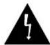
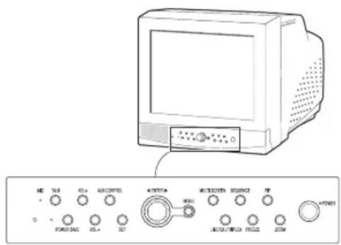
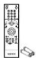
Names and Functions of Parts
Front Panel/Remote Control
A. Power Switch
Turns the power on/off.
B. POWER SAVE
Changes to Power Save mode.
C. VOLUME +/-
Controls the volume level.
D. TALK
Communicates with the doorbell in duplex mode.
E.AUX CONTROL
Outputs relay pulses to an external device for a specified time. You can adjust this control according to your environment. (For example, when the doorbell rings, you can move to the corresponding camera and identify the visitor before opening the door using the AUX CONTROL button.)
F.LIVE/P.B/TRIPLEX
Changes the Display mode. Each press of this button switches between Live, P.B., and Triplex modes sequentially.
G. SET
Enters the selected Sub Menu from the Main Menu.
H. ROTARY WHEEL (LEFT, RIGHT, ENTER)
Press the LEFT button to direct the camera to the left; the RIGHT button, to the right. In the center is the ENTER button. Use this wheel to move a Zoomed-in screen, or to scroll through Menu items or channels. Press ENTER to select an item, enter a sub menu, or replay the events.

I.MENU
Display the Setup menu on the screen. Press it again to exit the Setup menu.
J. MULTISCREEN
Switches to the split screen view. Each press of this button changes to the 4, 8, and 9-split screen sequentially. Only the 9 and 16 split screens are available in the Triplex mode.
K. SEQUENCE
When pressed in the full screen mode, channels are switched automatically and sequentially within a specified time period.
L. FREEZE
Captures the selected screen as a still screen. Refer to the section "When you want to watch in FREEZE screen mode" on page Eng-7.
M. PIP
Selects the Picture in Picture mode.
N.ZOOM
When pressed in full screen mode, the screen is enlarged. Each press of this button enlarges the screen two times sequentially and then returns to the normal size. Use the Rotary Wheel to move the Zoomed-in screen.
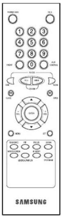
O.Number Key(0~9)
Press the number of the channel to watch it in full screen mode. Or, press the SYSTEM ID button and then press the number of the system you want to control with the remote control.
P.ZOOM(TELE/WIDE)
Only the remote control has this button. It is available only when a camera (SOC-420(P), SOC-920(P) sold separately), is connected to the system.
Q. FOCUS(FAR/NEAR)
Only the remote control has this button. It is used for camera Focus control and available only when a camera (SOC-420(P), or SOC920(P), sold separately), is connected to the system.
R. IRIS(CLOSE/OPEN)
Only the remote control has this button. It is used for camera Iris control and available only when a camera (SOC-420(P), or SOC-920(P), sold separately), is connected to the system.
S. ONEAF
Performs Auto Focus for the selected camera once in the present status. Only the remote control has this button. It is only available when a camera (SOC-420(P), or SOC-920(P), sold separately), is connected with the product.
T.SYSTEM ID
Selects the system to control with the remote. Only the remote control has this button.
U. ID RESET
Located on the remote control, this button resets the selected System ID to the default ID (1).
Rear Panel
A.CAMERA IN(RJ-45)
Video camera input terminals. You can connect up to 8 cameras with RJ-45 connectors.
B.CAMERA IN (BNC)
Video camera input terminals. You can connect up to 8 cameras with BNC connectors.
Caution
Either RJ-45 or BNC type cameras should be connected to the same channel. Signal interference will occur if both types of camera are connected to the same channel.
C.VCR
- Connects to the VCR using a 6-pin connector.
- TRIGGER: Trigger output terminal for the VCR
VIDEO IN/OUT: Video input/output terminal for the VCR - AUDIO IN/OUT: Audio input/output terminal for the VCR
D.AUX
- Connects to another device using the 4-pin connector.
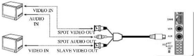
- SPOT VIDEO OUT: The terminal that allows you to supervise the specified channel within the Main screen on the additional connected monitor.
- SPOT AUDIO OUT: The terminal that allows you listen to the sound of the specified channel on the additional connected monitor.
- SLAVE VIDEO OUT: The terminal that allows you to view the Main screen displayed at the present time on the additional connected monitor.
E. ALARM
A/O (HOT/COLD): When an alarm occurs, the Active Make signal is output.
- A/R: Connects to the Alarm Reset terminal of VCR. When an alarm is triggered, a pulse is output.
G: Connects to the ground terminal of VCR.
F. AC IN
Connects the power cord.
Chapter 2: Installation
Installation Environments
This section describes the environmental requirements for safe installation and use.
Install the product on a flat table or in a rack. It should be used only when level and should not be used when stood vertically or obliquely.
The location in which the main system is installed and the configuration of the wiring room are very important for proper operation of the system.
When the products are installed too closely together or the location is poorly ventilated, the system may not operate properly and maintenance of the system may be difficult.
Sufficiently circulate the air within the system operating room and tightly fasten the cover of the main system to prevent malfunction and reduce system downs due to environmental causes.
There are high voltage parts inside. Do not arbitrarily open the cover.
Install the product in a place that meets the following environmental conditions. Be sure to maintain the system under the temperatures and humidity conditions given below:
- Operating temperature: 0^ 40^
Storage temperature: -20^ 60^ - Operating humidity: 20% 85% RH
Storage humidity: 20% 95 RH - Input voltage: AC 100 ~ 240V
Frequency: 50 / 60Hz
Caution
When operating the product, the fluctuation of input voltage must be within 10% of the rated voltage and the external power outlet must be grounded, otherwise, it may cause electric shock or malfunction of the product. Do not connect heat-generating appliances such as a hair dryer, iron or refrigerator to the same power outlet in which the product is plugged, otherwise it may cause a fire or malfunction of the product. The use of an Automatic Voltage Regulator (AVR) is highly recommended to ensure that stable power is supplied.
Be sure to coil CORE-FERRITE on the connector to reduce electro-magnetic interference (EMT).
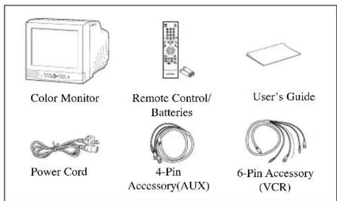
Unpacking
Remove the package cover and place the product on a flat and secure surface or in the installation location. Check whether all the following devices and accessories are included with the main system.
Chapter 3: Connecting to External Devices
The product can be connected to an external device such as a monitor, VCR, Alarm Box, Door Bell Box, etc.
This chapter describes how to connect to external devices.
Caution
Make sure not to input more than 2V from the camera, video, or audio source, otherwise, it may cause a malfunction of the product.
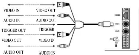
1. Connecting to Time Lapse VCR
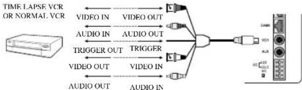
(or Normal VCR)
1) Connect the 6-pin plug to the VCR terminal on the real panel.
2) Connect the VIDEO OUT plug to the VIDEO IN terminal of the VCR.
3) Connect the VIDEO IN plug to the VIDEO OUT terminal of the VCR.
4) Connect the AUDIO OUT plug to the AUDIO IN terminal of the VCR.
5) Connect the AUDIO IN plug to the AUDIO OUT terminal of the VCR.
6) Connect the TRIGGER plug to the REC TRIGGER OUT terminal of the VCR.
7) Connect the A/O (HOT) terminal on the rear panel to the Alarm IN terminal of the VCR.
8) Connect the A/O (COLD) terminal on the rear panel to the Ground terminal of the VCR.
9) Connect the A/R terminal on the rear panel to the Alarm Reset terminal of the VCR.
10) Connect the G (ground) terminal on the rear panel to the Ground terminal of the VCR.
Caution
The name of the REC TRIGGER OUT or Alarm terminal may change depending on the type of Time Lapse VCR.
Make sure to check the names of the terminals before connecting them.
2. Connecting the Alarm Sensor
Connect the Alarm Box and Alarm Sensor in accordance with the user manual of Alarm Box.
3. Connecting the Door Bell Box
Connect the cameras and Door Bell Box in accordance with the user manual of Door Bell Box.
4. Connecting the Ordinary monitor
Connect the ordinary monitor to the Spot output terminal, which allows you to supervise a specified channel within the Main screen. Connect the Slave Monitor to the output terminal, which allows you to simultaneously view the current situation.
Chapter 4: Basic Operation
1. Basic Operation
1) Turn the Power Switch On.
When turned on for the first time, the 9-split screens are displayed on the monitor. At this time, the channels that have no input are displayed with a blue screen and video loss occurs. (After completing the initial setup, the settings are memorized when the power is turned off. Therefore, when you turn the power on again, the product will be operated with the previous settings.)
2) Select a Display Mode as follows.
- Full Screen Mode: When you are on a split screen, move to your desired channel using the Rotary Wheel and press the ENTER button located at its center. The selected channel will then be displayed in Full Screen Mode.
- Multi Screen Mode: Press the MULTISCREEN button to display the split screens. You can select which channels will be displayed on the split screen.
- Sequence Screen Mode: Press the SEQUENCE button. Channels are automatically switched sequentially in full screen mode.
- Freeze Screen Mode: You can capture and view a still screen using the FREEZE button and the Rotary Wheel.
- LIVE/P.B. Screen Mode: You can monitor the present camera signals or playback the recorded screens using the LIVE/P.B./TRIPLEX button.
- TRIPLEX Screen Mode: Watch the present camera signals and recorded screens on the same monitor using the LIVE/P.B./TRIPLEX button.
- PIP Screen Mode: You can watch Picture in Picture (PIP) screens by using the PIP button.
- Zoom Screen Mode: You can enlarge a full screen two times using the Zoom button and Rotary Wheel.
2. When you want to watch on LIVE/P.B./TRIPLEX screen.
Select the LIVE, P.B., or TRIPLEX screen mode using the LIVE/P.B./TRIPLEX button. Each press of this button changes the screen mode to LIVE mode, P.B. mode, and TRIPLEX mode sequentially.
The LIVE/P.B/TRIPLEX button will not operate in the following cases:
- While using the SETUP Menu
- While displaying the Event List or the Door Bell List
While replaying events
While zooming-in the screen
While setting a still screen on the multi screen mode
3. When you want to watch in Full Screen Mode
If you are on a split screen, move to your desired channel using the Rotary Wheel and press ENTER. The selected channel will be displayed in full screen mode. At this time, you can change the channel using the Rotary Wheel.
In addition, you can change the channel by pressing number buttons on your remote control.
4. When you want to watch in Sequence Screen Mode
The Sequence screen is available only in full-screen LIVE mode. Press the SEQUENCE button when the screen is in full-screen LIVE mode to switch to the Sequence screen. You can set the switching intervals by going to "SEQUENCE" under "4. SYSTEM SETTING" on the SETUP MENU. The range of switching intervals is from one to thirty seconds. Press the SEQUENCE button again to stop the screen displayed at the present time.
The SEQUENCE button will not operate in the following cases:
- While operating in P.B. or TRIPLEX mode
- While using the SETUP Menu
While displaying a split screen
While displaying the Event List or Door Bell List
While replaying events - While zooming-in the screen
5. When you want to watch in FREEZE Screen Mode
You can stop a full or split screen temporarily and view the still screen in LIVE, P.B., TRIPLEX mode.
You can select and stop the channels you wish to stop in split screen mode.
1) Full Screen Display
If the FREEZE button is pressed, the current display will freeze, and the FREEZE icon will appear in the upper right corner of the screen. Press the FREEZE button again to exit this mode.
2) Multi-Screen Display
① If the FREEZE button is pressed, the FREEZE icon will appear in the upper right corner of the screen.
② Move to the picture you would like to freeze by using Rotary Wheel.
③ By pressing the ENTER button in the middle of Rotary Wheel, the picture from that channel will freeze, and the character “F” will appear. Press the ENTER button again to exit this mode.
④ If you would like to see the frozen picture from another channel, move to the target channel, and press ENTER.
The new channel's picture will be frozen, and the character "F" will appear. Press the ENTER button again to exit this mode.
⑤ If the picture on any other channel remains frozen, repeat item ④
⑥ Press the FREEZE button to exit entirely from FREEZE mode.
The FREEZE button will not operate in the following cases:
While using the SETUP Menu
- While displaying the Event List or Door Bell List
While replaying events
6. When you want to watch on ZOOM Screen Mode
This mode is operated only while in LIVE/P.B. Mode Full Screen.
1) When the ZOOM button is pressed, a ZOOM AREA will appear in the center of the screen.
2) Move the ZOOM AREA to the target position by using the Rotary Wheel and the ENTER button.
3) Press the ZOOM button again to increase picture to double its original size.
4) Press it again to return to the original size.
ZOOM AREA and ZOOM Picture Movement
1) Press the ZOOM button and turn the Rotary Wheel to move the ZOOM AREA up and down over the picture.
2) Press the ENTER button and turn the Rotary Wheel to move the ZOOM AREA left and right over the picture.
3) Press the ENTER button again and turn the Rotary Wheel to move the ZOOM AREA up and down over the picture.
The ZOOM button will not operate in the following case:
- While using the SETUP Menu
- While Displaying the EVENT List or Door Bell List
While Replaying events - While operating in Sequence Mode
7. When you want to watch on PIP Screen Mode
You can watch a Picture in Picture screen in full-screen LIVE mode using the PIP button.
When you press the PIP button for the first time, the sub screen on the PIP screen is a sequence screen. After that, when you enter into PIP mode again, the sub screen which is displayed in the same screen mode as when you exited the PIP mode previously.
Using PIP Screen
1) Press the PIP button in full-screen LIVE mode.
2) When a fixed channel is displayed on the sub screen, each time you press ENTER it switches between the Main screen and the Sub screen.
3) Turn the Rotary Wheel to change the channel of the Main screen.
4) Press the SEQUENCE button to set the Sub screen as the sequence screen. Press the button again to fix the channel.
5) You can change the position of the sub screen by going to "PIP POSITION" under "2.CLOCK/DISPLAY SET" on the SETUP menu.
The PIP button will not operate in the following cases:
While operating in P.B. or TRIPLEX mode
While displaying a split screen
- While using the SETUP Menu
While displaying the Event List or Door Bell List
While replaying events
While zooming-in the screen
While operating in Sequence mode
In case of no Video input signal
- When the input signal channel is in the Full-screen mode at the time of Single video input
8. When you want to watch the VCR output
Change to PB FULL Mode by pressing the Live/P.B./TRIPLEX button. The "PB THROUGH" picture will appear if the ENTER button is pressed while in this mode. Press the "ENTER" button again to return to the previous PB picture.
Caution
This function is only available in PB FULL Display mode.
9. When you want to watch the Event Replay screen
1) When an Alarm/Motion signal is input
You can use the alarm function only when an Alarm Box is connected. When an alarm/motion signal is input, the word "EVENT" is displayed on the screen, and a warning buzzer sounds. When this occurs, if you press ENTER, up to 16 frames before and after the generated alarm/motion signal are replayed on the Event Replay window.
Press ENTER again to stop the event replay.
If alarm/motion signals are input on more than one channel, press ENTER to start the event replay for another channel when the current event replay finishes. When an event replay for all the channels on which an alarm/motion signal has occurred has finished, press ENTER to exit Event Replay mode.
Alarm/Motion histories are recorded in the EVENT LIST.
2) When Channel Loss is detected
If the channel loss detection function detects a channel loss, the word "EVENT" is displayed on the screen and a warning buzzer sounds. When this occurs, press ENTER and up to 16 frames before the detected channel loss are replayed on the Event Replay window.
Press ENTER again to stop the event replay. If channel loss is detected on more than one channel, press ENTER to start event replay for the next channel when the current event replay finishes.
When the event replay for all the channels on which channel loss has been detected finishes, press ENTER to exit the Event Replay mode. Channel loss histories are recorded in the EVENT LIST.
10. When you want to watch a Door Bell screen
The Door Bell Function is only available with a door bell connection. When the door bell is pressed, the current picture switches to the doorbell area monitoring picture, in full screen mode, along with an alarming beep. At this time, one Instant Picture is stored in the "DOOR BELL LIST". Up to 8 pictures can be stored in the "DOOR BELL LIST".
You can access any stored picture from the list to be displayed on the screen.
Move to your desired item by going to "5. DOOR BELL LIST" on the SETUP menu and press ENTER to display it as a still screen.
Then, press ENTER again to return to the "DOOR BELL LIST" screen.
Chapter 5: Setup Menu Settings
- Press the MENU button to display the Language Selection screen.

- Select the desired language by using the Rotary Wheel and press ENTER to display the SETUP MENU in the desired language.
- When you press the MENU button after completing the initial language selection, the Language Select screen will not appear. Instead the following SETUP MENU will appear on the monitor. Press the button once again to return to the previous menu.
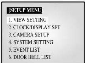
- Select submenu 1 to 6 from the SETUP MENU using the Rotary Wheel and press ENTER to go to the SUB MENU.
1. VIEW SETTING
You can change the contrast, brightness, color, sharpness and tint of the Main screen on the monitor. Select "I. VIEW SETTING" from the SETUP MENU using the Rotary Wheel and press ENTER to display the following screen:
-
Select an item using the Rotary Wheel and press ENTER to change the preset value.
-
Change the presct value (0 ~ 100) by using the Rotary Wheel and press ENTER to save the setting.
- Select SAVE (save the changes), QUIT (exit the setting mode without saving) or PRESET (reset all the settings to the factory defaults) from the EXIT MENU and press ENTER to return to the SETUP MENU.
Caution
The "TINT" item is only available in NTSC SYSTEM mode.
2. CLOCK/DISPLAY SET
You can change PIP position, display type, date type and time. Select "2. CLOCK/DISPLAY SET" from the SETUP MENU using the Rotary Wheel and press ENTER to display the following screen:
- Select an item using the Rotary Wheel and press ENTER to change the preset value.
- Change the preset value using the Rotary Wheel and press ENTER to save the setting.
- Press the MENU button to return to the SETUP MENU.
PIP POSITION: BOTTOM-RIGHT TOP-LEFT TOPRIGHT BOTTOM-LEFT.
- Select the PIP position among the four options listed above.
DISPLAY TYPE: ALL TITLE DATE/TIME NONE.
- ALL: All items will be displayed except the DATE/TIME and the TITLE.
- TITLE: Only the CHANNEL TITLE will be displayed.
- DATE/TIME: Only the DATE/TIME will be displayed.
- NONE: Neither the DATE/TIME nor the TITLE will be displayed.
BORDER COLOR: GRAY BLACK
- GRAY : BORDER LINE COLOR is displayed in GRAY in Multi Screen mode.
- BLACK: BORDER LINE COLOR is displayed in BLACK in Multi Screen mode.
DATE TYPE: YY/MM/DD MM/DD/YY DD/MM/YY. DATE [YY/MM/DD]
- YearYY)00(2000) 99 (2099)
Month(MM):01\~12
DayDD)01\~31
TIME [HH:MM:SS]
Hour(HH):00\~23
- Minute(MM):00~59
Second (SS):00 59
3.CAMERA SETUP
You can change the Camera ID, LOSS DETECT, MOTION DETECT and Camera Presct values.
Select "3. CAMERA SETUP" from the MAIN MENU using the Rotary Wheel and press ENTER to display the following screen.
Select the desired channel using the Rotary Wheel and press ENTER to go to the display of the selected channel. The following screen will appear.
- All the items, except "CAMERA ID" and "LOSS DETECT," will be available for setting only after the system is connected to a camera (SOC-420(P) or SOC-920(P), sold separately).
- Select the desired item using the Rotary Wheel and press ENTER. Then change the presct value using the Rotary Wheel and press ENTER to complete the setting.
- Select SAVE (save the changes), QUIT (exit the setting mode without saving) or PRESET (reset all the settings to the factory defaults) from the EXIT menu and press ENTER to return to the previous CAMERA SETUP menu. You can't return to the previous menu while in the setting mode. You can only return to the previous menu by selecting EXIT.
- Change the preset values for the other channels repeating the same steps.
- Press the MENU button after completing all the settings to return to the SETUP MENU.
CAMERA ID: --CH1----("-" indicates blank.)
- Select "CAMERA ID" using the Rotary Wheel and press ENTER to select the first ".
- Select the desired letter using the Rotary Wheel and press ENTER to move on and select the next letter. (Letter order: 0123456789ABCDEFGHIJKLMNOPQRSTUVWXYZ)
- Repeat the same to select all the desired letters. (You can choose up to ten letters.)
LOSS DETECT: Sets the Loss Detect On/Off. (ON Off)
IRIS: Controls the video output level through the Iris depending on the level of light coming into the camera.
- Select "IRIS" using the Rotary Wheel and press ENTER to select
either "ALC..." or "MANUAL...".
-
ALC...: Auto Light Compensation
-
Select "ALC..." using the Rotary Wheel and press the SET button to display the following screen. Press the MENU button after completing the setting to return to the previous menu.
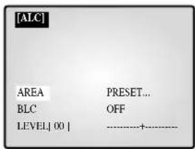
- Select AREA using the Rotary Wheel and press ENTER to select either "PRESET..." or "USER...".
- Select "PRESET..." using the Rotary Wheel and press the SET button to display the following screen. The back light compensation will be applied to the area(s) with preset values.

Press the MENU button to return to the previous menu.
- Select "USER..." using Rotary Wheel and press the SET button to display the following screen.
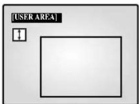
Adjust the size up/downward using the Rotary Wheel and press ENTER to select and move on to adjust the size on the left/right side. Then "E" will be displayed on the screen.
Press ENTER after adjusting the size of the left/right side by using the Rotary Wheel. Then you will be ready to adjust the position up/downward and “□” will be displayed on the screen.
Press ENTER after adjusting the position using the Rotary Wheel. Then you will be ready to adjust the position to the left/right side and "□" will be displayed on the screen.
Press ENTER after adjusting the position using the Rotary Wheel. Then you have completed the AREA setting. Press the MENU button to return to the previous menu.
- BLC (Back Light Compensation): When BLC is turned "ON," BLC function will be applied to all the areas set in AREA. When bright light is in the background of an object, the object will appear dark on the monitor due to the backlight. To address this problem, use the BLC function so that you can get clear images.
LEVEL: You may set the video output level from "-9" to "+" Select "LEVEL [00]" using the Rotary Wheel and press ENTER to change the setting. Press ENTER after changing the setting to save the setting.
- MANUAL...: Sets the manual opening/closing of the Iris.
- Select "MANUAL..." using the Rotary Wheel and press SET button to display the following screen.
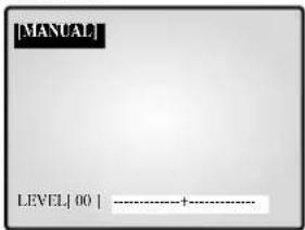
- Set the value using the Rotary Wheel.
- Press the MENU button to return to the previous menu.
SHUTTER
- You can set the high-speed electronic shutter speed, AUTO low-speed shutter speed and FIX low-speed shutter speed.
- High-speed electronic shutter can be set to 7 shutter speeds ranging from 1/120(1/100) sec to 1/10K sec. Auto low-speed shutter and FIX low-speed shutter can both be set to 12 shutter speeds ranging from X2 to X128.
- Low-speed slows down the speed of the shutter so that images taken in dark light appear clearer on the screen. Select AUTO low-speed shutter to detect the density of light and automatically slow down the speed of the shutter depending on the density. Select FIX low-speed shutter to set the speed of the shutter manually.
- The numbers following the AUTO and FIX items indicate the number of fields stored. The higher the number is, the lower the speed of the shutter becomes. Images, therefore, appear most clear with still pictures. With moving images, however, the object can appear blurred.
- Setting the Value
- From the SHUTTER Menu press ENTER to adjust the values. Select the value using the Rotary Wheel and press ENTER to complete the setting.
- OFF '1/120(1/100)' 1/250' 1/500' 1/1000' 1/2000' 1/4000'
- 1/10K 'OFF AUTO X2 'AUTO X4 'AUTO X6 'AUTO X8'
- AUTO X12 'AUTO X16 'AUTO X24 'AUTO X32 'AUTO X48'
- AUTO X64 'AUTO X96 'AUTO X128 'OFF 'FIX X2 'FIX X4'
- FIX X6 'FIX X8 'FIX X12 'FIX X16 'FIX X24 'FIX X32 'FIX X48 'FIX X64 'FIX X96 'FIX X128.
WHITE BALANCE: ATW,AWC.,MANUAL...
- You can turn on the White Balance function that enables the color white to appear normal regardless of the color temperature of light.
- ATW: Monitors the change in color temperature and adjusts the setting of the White Balance accordingly.
- AWC: Adjusts the setting of the White Balance to the color temperature only once and then maintains the setting. While in the AWC screen, place a white paper in front of the camera and press the SET button.
- MANUAL...: Select "MANUAL" using the Rotary Wheel and press the SET button to display the following screen. Then you can choose 3200K, 5600K or USER Mode and set the White Balance manually depending on the current lighting conditions.
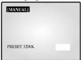
- 3200K: Sets the color temperature at 3200^ .
- 5600K: Sets the color temperature at 5600^ .
- Set to "OFF[USER]" to display the following screen. Press ENTER and then select the proper values of RED and BLUE to manually set the color temperature.
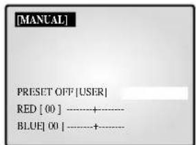
Press the MENU button to return to the previous menu.
SPECIAL...
- Select "SPECIAL..." using the Rotary Wheel and press ENTER to display the following screen. Press the MENU button after completing the setting to return to the previous menu.
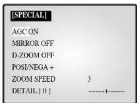
AGC: AGC(Auto Gain Control) function On/Off.
- MIRROR: Horizontally reverses the video output signals.
- D-ZOOM: Sets the magnifying rate of the Digital Zoom. This system offers up to 10X Zoom.
- POSI/NEGA : Sets the video output signals to either normal or reverse output.
- ZOOM SPEED: Sets the moving speed of the Zoom.
- 1: Takes about 17 sec from x1 to x12 (the lowest speed)
- 2: Takes about 10 sec from x1 to x12 (low speed)
- 3: Takes about 6 sec from x1 to x12 (high speed)
- 4: Takes about 3 sec from x1 to x12 (the highest speed)
DETAIL: Adjusts brightness vertically and horizontally.
FOCUS: Set the Focus to MF or ONEAF.
- MF: Manual Focus Mode allows the user to Focus.
-
ONEAF: When the Zoom moves from the Wide to the Telephoto direction, AF occurs only once after the Telephoto function is completed.
-
ONEAF works like MF Mode when there are still images and like AF Mode when the Zoom moves in the Telephoto direction.
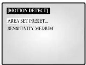
MOTION DETECT...
- The Motion Detect feature is used to detect motion of an object. By turning on the Motion Detect, you can detect the motion of an intruder during non-peak hours.
- Select "MOTION DETECT" using the Rotary Wheel and press ENTER to display the following screen. Press the MENU button after completing the setting to return to the previous menu.
-
AREA SET: Sets the area of the screen to which the Motion Detector is applied.
-
PRESET.
1 Select "PRESET" using the Rotary Wheel and press the SET button to display the following screen. The Motion Detect is applied to the area(s) within the box.

Press the MENU button to return to the previous menu.
- USER...
1 Select "USER..." using the Rotary Wheel and press the SET button to display the following screen.
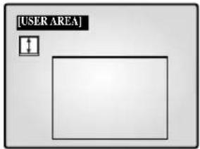
Adjust the size up/downward using the Rotary Wheel and press ENTER to select and move on to adjust the size of left/right side. Then " " will appear on the screen.
Adjust the size of the left/right side by using the Rotary Wheel and press ENTER to select and move on to adjust the position up/downward. “□” will appear on the screen.
Adjust the position up/downward using the Rotary Wheel and press ENTER to select and move on to adjust the position of the left/right side. "□" will appear on the screen.
Adjust the position of the left/right side using the Rotary Wheel and press ENTER. Then you will have completed the AREA setting. Press the MENU button to return to the previous menu.
- SENSITIVITY: Sets the sensitivity of the Motion Detector to LOW, MEDIUM or HIGH.
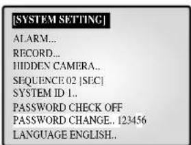
4. SYSTEM SETTING
You can change the ALARM, RECORD, HIDDEN CAMERA, SEQUENCE, SYSTEM ID, PASSWORD, and LANGUAGE settings.
Select "4. SYSTEM SETTING" from the SETUP MENU using the
Rotary Wheel and press ENTER to display the following screen.
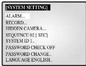
-
Select an item using the Rotary Wheel and press ENTER to change the setting.
-
Change the setting using the Rotary Wheel and press ENTER to save the setting.
-
Press the MENU button after completing all the settings to return to the SETUP MENU.
ALARM...
- Select "ALARM" using the Rotary Wheel and press ENTER to display the following screen.
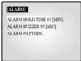
ALARM HOLD TIME
ALARM HOLD TIME is the time during which the Alarm continues. You can set the duration at 5 sec, 15 sec, 30 sec, 1 min, 3 min, 5 min, 10 min, 20 min, 30 min or AUTO. When you select AUTO, the Alarm will be on during the time the Alarm is signaling.
ALARM BUZZER
When the Alarm occurs, the Alarm Buzzer is set off. You can set the duration at 5 sec, 15 sec, 30 sec, 1 min or OFF. When you select OFF, the Alarm Buzzer will not sound.
- Select "ALARM PATTERN" using the Rotary Wheel and press ENTER to display the following screen.
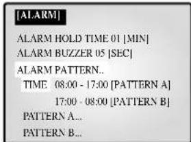
- You can select when to arm and disarm the alarm in two patterns. When you select PATTERN A, The time in PATTERN B will be automatically modified.
- Select PATTERN A using the Rotary Wheel and press ENTER to display the following screen.
- Choose On/Off for the Motion, Alarm and Door-Bell features for all 8 cameras.
- Press the MENU button after completing the settings to return to the ALARM Menu.
- Repeat the same for PATTERN B.
- The “-” will be displayed when it is not connected to the accessories.
RECORD...
- Select "RECORD..." using the Rotary Wheel and press ENTER to display the following screen.
| [RECORD] | |
| REC TYPE | NOR |
| REC OUT | FRAME |
| AUDIO RECORD CH1 | |
| SPOT - OUTPUT | CH1 |
REC TYPE
NOR: Used for recording with a normal VCR. The picture is displayed according to the "REC OUT" set values (FIELD, FRAME).
- TLV: Used for recording through a time lapse VCR.
REC OUT
It is valid when the REC TYPE is "NOR".
- FIELD: Records at 1/50 seconds (PAL), 1/60 seconds (NTSC).
- FRAME: Records at 1/25 seconds (PAL), 1/30 seconds (NTSC).
AUDIO RECORD
Sets the channel that sends Audio signals to the recoding output.
SPOT-OUTPUT
Sets the output channel for SPOT which will intensely monitor that channel.
- Press the MENU button after completing the settings to return to the SYSTEM SETTING Menu.
HIDDEN CAMERA
- Select "HIDDEN CAMERA..." using the Rotary Wheel and press ENTER to display the following screen.
- Turn the Hidden Camera On/OFF of in LIVE Modc and P.B. MODE for each channel.
- Press the MENU button after completing the settings to return to the SYSTEM SETTING Menu.
SEQUENCE
- Set the Switching Interval for Sequence Mode. You can set the time between 1 sec and 30 sec.
SYSTEMID
- This function allows the user to control a single monitor using the remote control when multiple (up to 10) monitors are linked together. Only those monitors with IDs matching the Remote Control ID will be controlled by the remote control.
| CH1 | CH2 | CH3 |
| MONITOR ID:1 REMOCON ID:1 | ||
| CH4 | CH5 | CH6 |
| CH7 | CH8 | |
- Setting: The default value of the monitor and the remote control is "1". The value of the Monitor ID can be set from 0 to 9 by accessing the System ID Setup mode under the System Setting menu. Press the System ID button on the remote control to display the Monitor ID and the Remote Control ID as shown above. With system ID button pressed, enter the desired number by pressing the corresponding button (0 to 9) to set up the Remote Control ID. The OSD will disappear three seconds after the last button is pressed.
PASSWORD CHECK
- Turns the Password Check On/OFF for entry into the SETUP MENU.
- When PASSWORD CHECK is "ON" for entry into the SETUP MENU, the following screen will appear and the first space for a number will be selected.
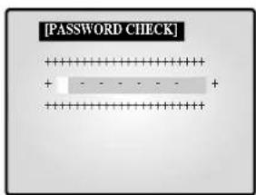
- Select the first digit of the Password using the Rotary Wheel and press ENTER to move to the next digit. Repeat this step to enter the six-digit password and press ENTER to return to the SETUP MENU.
- If the Password is not correct, "ERROR TRY AGAIN" will appear at the bottom of the screen. The message will disappear after the first digit of the Password is entered. Repeat this step until you have entered the six-digit password then press ENTER to move to the SETUP MENU. If the number is entered incorrectly more than three times, the display will return to the previous menu.
TOKEN CHANGE...
- Select "password CHANGE..." using the Rotary Wheel and press ENTER to display the current Password on the screen as shown below. The first digit of the number will be selected. (Factory default is 123456.)
-
Select the first digit of the Password using the Rotary Wheel and press ENTER to select the second digit. Repeat the same until the six digits of the Password have been entered. Press ENTER to complete the change.
-
You can use "0" to "9" for the Password.
LANGUAGE
- Select the desired language for the use in the Menu. ENGLISH, ESPANOL, FRANÇAIS, ITALIANO, DEUTSCH, NEDERLANDS and PORTUGUES are available.
5. EVENT LIST
You can check the ALARM/MOTION/LOSS EVENT LIST. Select "5. EVENT LIST" from the SETUP MENU using the Rotary Wheel and press ENTER to display the following screen.
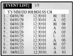
- The latest information on Alarms, Loss and Motion Detects will be stored. This system stores up to 50 events (10 x 5 pages) staring from the latest one. You can check the other pages of the List by using the Rotary Wheel.
- Press the MENU button to return to the SETUP MENU.
6. DOOR BELL LIST
Tocheck the EVENT LIST of the DOOR BELL(S). Select "6. DOOR BELL LIST" from the SETUP MENU using the Rotary Wheel and press ENTER to display the following screen.
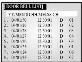
- The latest information from the Door Bell detector will be stored. This system stores up to 8 events starting from the latest one. Scroll down the List using the Rotary Wheel and press ENTER to display the still screen of the corresponding Door Bell. Press ENTER to return to the DOOR BELL LIST.
- Press the MENU button to return to the SETUP MENU.
Chapter 6: Recording
1. Recording in Time Lapse (or Normal) Mode
- Image signals transmitted from up to 8 cameras play at 1/25 or 1/50 second intervals in PAL SYSTEM areas, and at 1/30 or 1/60 second intervals in NTSC SYSTEM areas, and are recorded in the VCR.
- The TRIGGER OUT port of the VCR must be connected to the TRIGGER (6PIN VCR Accessory) port of this system.
- When trigger signals from the VCR stop for more than 30 sec, the Self Trigger mode is turned on to continue recording without the trigger from the VCR.
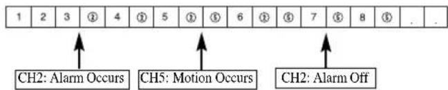
2. Alarm/Motion Channel Intensive-Recording
- This system double-records channels in case of an Alarm/Motion.
- It records the Alarm/Motion channels in between recording the output channels.
The "VIDEO LOSS" channel is also subject to the Alarm/Motion Channel Double-Recording. - Ex.) The ALARM is turned on at CH2. Then MOTION occurs at CH5.
Chapter 7: Alarm, Motion, Loss and Door Bell
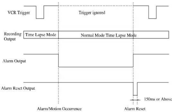
1. Alarm Occurrence
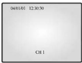
The Alarm becomes available only when an Alarm Box is connected. 1) When an Alarm trigger is received, a warning buzzer sounds and the screen is divided into 9 Live-Mode sub-screens. The word "EVENT" appears on the screen and the Alarm occurrence information is displayed at the right bottom of the screen.
| 04/01/01 | 12:30:30 | EVENT |
| CH1 | CH2 | CH3 |
| CH4 | CH5 | CH6 |
| CH7 | CH8 A12B45678 | |
2) Press ENTER (in the middle of the Rotary Wheel) to replay the event in Event Replay mode. Up to 16 screens can be replayed centering on the time of the Alarm. The duration of Replay is displayed in a graph. Turn the Rotary Wheel during the Replay to forward or reverse the stored screens one by one. Press ENTER to terminate the Event Replay. The Event Replay will continue until ENTER has been pressed.
| 04/01/01 | 12:30:30 | EVENT CH3 |
| 1 | CH2 | |
| CH4 | CH5 | CH6 |
| CH7 | CH8 | ALARM 04/01/01 12:29:30 |
3) Alarm occurrence information is stored in the "EVENT LIST".
4) Alarm Out (HOT, COLD) signals are active during the "ALAR HOLD TIME."
- ALARM HOLD TIME : Time during which the Alarm function is carried on after the Alarm is first detected. Alarm Hold Time is reset automatically when Event Replay is turned on.
5) Recording output continues in Normal mode until the Alarm is cleared. The recording frequency of the corresponding channel increases.
6) Signals change as the Alarm occurs and later clears.
2. Motion Occurrence
The Motion option only becomes available when a camera with Motion features is connected.
1) When a Motion trigger is received, a warning buzzer sounds and the screen is divided into 9 Live-Mode sub-screens. The word "EVENT" appears on the screen and the Motion occurrence information is displayed at the bottom right of the screen.
| 04/01/01 | 12:30:30 | EVENT |
| CH1 | CH2 | CH3 |
| CH4 | CH5 | CH6 |
| CH7 | CH8 M12345678 |
2) Press ENTER (in the middle of the Rotary Wheel) to replay the event in Event Replay mode. Up to 16 screens can be replayed centering on the time of the Motion occurrence.
The duration of the replay is displayed in a graph.
Turn the Rotary Wheel during the Replay to forward or reverse the stored screens one by one.
Press ENTER to terminate the Event Replay. The Event Replay will continue until ENTER has been pressed.
| 04/01/01 | 12:30:30 | |
| 1 | CH2 | EVENT CH3 |
| CH4 | CH5 | CH6 |
| CH7 | CH8 | MOTION 04/01/01 12:29:30 |
3) Motion occurrence information is stored in the "EVENT LIST".
4) Alarm Out (HOT, COLD) signals are active during "ALARM HOLD TIME".
5) Recording output continues in Normal mode until the Motion is cleared. The recording frequency of the corresponding channel increases.
6) Signal output continues as the Motion occurs and later clears.
3. Loss Occurrence
1) When the Loss occurs, a warning buzzer sounds and the screen is divided into 9 Live-Mode sub-screens. The word "EVENT" and Loss channel appears on the screen and the corresponding channel appears Blue Black. When more than one Loss occurs, that channel number displays switches to Blue-Black with a 1 second interval.
| 04/01/01 | 12:30:30 | L12345678 EVENT CH3 |
| CH1 | CH2 | |
| CH4 | CH5 | CH6 |
| CH7 | CH8 |
2) Press ENTER (in the middle of the Rotary Wheel) to replay the event in the Event Replay mode. Up to 16 screens can be replayed centering on the time before the Loss occurrence. The duration of the Replay is displayed in a graph.
Turn the Rotary Wheel during the Replay to forward or reverse the stored screens one by one.
Press ENTER to terminate the Event Replay. The Event Replay will continue until ENTER has been pressed.
| 04/01/01 | 12:30:30 | L12345678 |
| CH2 | EVENT | |
| CH3 | ||
| CH4 | CH5 | CH6 |
| CH7 | CH8 | LOSS |
| 04/01/01 | ||
| 12:30:00 |
3) Loss occurrence information is stored in the "EVENT LIST".
4) When the corresponding camera is reconnected, the old settings are canceled and the factory default settings are reinstated.
4. Door Bell Occurrence
The Door Bell option is only available when a Door Bell Box is connected.
1) When a door bell is pressed, the current picture switches to the doorbell area monitoring picture, in full screen mode, along with an alarming beep.
2) When the Door Bell is pressed, a still screen is stored in the "DOOR BELL LIST".
3) Up to 8 still images can be stored in the "DOOR BELL LIST" and the selected List can be displayed on the screen.

4) Select the desired list from "6. DOOR BELL LIST" in the SETUP MENU and press ENTER in to replay the still screen of the corresponding Door Bell. Press ENTER again to return to the "DOOR BELL LIST".
Appendix
Specifications
1. Model Name
- SMO-210TRN(P)
- SMO-150TRN(P)
2. Video Input
- CAMERA 8 Input: 1.0Vp - p 75 (vertical),
RJ-45 Type, CVBS
- VCR 1 Input (to Video Out of VCR): 1.0Vp - p 75 (vertical),
S-Jack Type, CVBS
3. Video Output
- Monitor 2 Output
SPOT:1.0 Vp-p,75Ω (vertical),S-Jack Type,CVBS
SLAVE:1.0 Vp-p,75Ω (vertical),S-Jack Type,CVBS
- VCR 1 Output: 1.0 Vp-p, 75Ω (vertical), S-Jack Type, CVBS
4. Voice Input
-CAMERA8Input:RJ-45Type
- VCR 1 Input (Audio Out-VCR): S-Jack Type
5. Voice Output
SPOT Audio
- VCR Audio
6. Alarm/Motion Function: Connected Alarm Box/Camera
-A/O (HOT, COLD): Relay Active
-A/R (Alarm Reset): Open Collector "L" Level,
Pulse Width = 150ms or above
-Alarm Hold Time: Select 5sec, 15sec, 30sec, 1min, 3min, 5min,
-
If AUTO is selected, the Alarm will be on during the time the Alarm trigger is received.
-
Sequence: Select between 01 sec to 30 sec.
8. Event Replay
- Alarm/Motion/Loss: Max. 16 Frames per Channel
- Door Bell: Max. 8 Frames
9.List
- Alarm/Loss/Motion: Saving Max. 50
- Door Bell: Max. 8
10. Multi Screen
- Full, 4, 8, 9, 16, Zoom, PIP
11. Horizontal Resolution
- 400 TV Lines or more (Live Mode Full Screen)
12. Memory Back Up
- 5 Years or more
13. Operation Temperature
-0^ 40^
14. Built-in Clock
- ± 1 Minute/Month or less
15.CRT
- SMO-210TRN(P) : 21"FLAT CRT
- SMO-150TRN(P) : 15"FLAT CRT
16. Dimensions (W x H x D)
- SMO-210TRN(P): 520 x 509 x 486
- SMO-150TRN(P):388 x 459 x 379
17. Weight
-
SMO-210TRN(P) : 28kg (without packing)
32.5kg (with packing) -
SMO-150TRN(P): 15.2kg (without packing)
18.5kg (with packing)
18. Power consumption
- Please see the regulatory label attached on the back of the monitor.
19. Video system
- SMO-210TRP/150TRP: ONLY PALVIDEO SYSTEM
- SMO-210TRN/150TRN: ONLY NTSCVIDEO SYSTEM
Troubleshooting
You may encounter an unexpected problem while using this system that makes it hard to use the system properly. In many cases, however, they are minor problems rather than serious flaws in the system. Refer to the following tips for some possible solutions.
| When power will not come on | ·Make sure that the cord is properly plugged in. ·Check the power cable. |
| When the screen does not appear | ·Check the connections with the camera, accessories and the external monitor. |
| When record is not working | ·Make sure the Video In port of the VCR and the VCR Accessory Video Out port of this system are properly connected. ·Check if the tape inserted into the VCR is able to record. ·Check that the REC Trigger Out port of the Time Lapse VCR is properly connected to the VCR Accessory TRIGGER (6PIN VCR ACCESSORY) port of this system when you record in the Time Lapse Mode. |
| When playback is not working | ·Make sure the Video Out port of the VCR and the VCR Accessory Video In port of this system are properly connected. ·Check if the Display Mode of this system is in P.B. Mode or Triplex Mode. |
| When the screen does not appear in the Auto Sequence Switch Mode | ·Check that the screen is in Live Mode. ·Check that the time of “SEQUENCE” under the SETUP MENU is properly set. |
If the problem persists, contact the local sales representative or service center for support.
Note
If the problem is related to VCR recording or playback, check the VCR as well.
COLOR MONITOR
SMO-150TRN(P)
SMO-210TRN(P)
Mode d'emploi


ATTENTION
RISQUE DE DECHARGE ELECTRIQUE NE PAS OUVRIR

ATTENTION:POUR REDUIRE LE RISQUE DE DECHARGE ELECTRIQUE,NE RETIREZ PAS LE CACHIE (NI LE PANNEAU ARRIERE).AUCUNE PIECE NE PEUT ETRE REPAREE PAR L'UTILISATEUR. ADRESSEZ-VOUS AU PERSONNEL QUALIFIE POUR LE DEPANNAGE.
Chapter 1: Presentation 4
Chapter 2: Installation .6
Environments de 1 installation .6
Déballage 6
Chapter 2: Installation
-Plein ecran,4,8,9,16,Zoom,PIP
R. IRIS (CLOSE/OPEN)
R. IRIS (CLOSE/OPEN)
R. IRIS (CLOSE/OPEN)
- Completa, 4, 8, 9, 16, Zoom, PIP
11. Resolución horizontal
K. SEQUENCE (sequential)
WITBALANS: ATW.AWC...MANUEEL...
FOCUS: Stelt de focus in op MF of ONEAF.
RESSALVAS IMPORTANTES
Cuidado
RESSALVAS IMPORTANTES 2
-Inteiro,4,8,9,16,Zoom,PIP
- Alarm Occurrence 14
2.Motion Occurrence 15 -
Loss Occurrence 15
-
Door Bell Occurrence.. 15
Appendiks 16
Specificationer 16
Fejlfinding. 16
Kapitel 1: Oversigt
Oversigt
2) Multi-Screen Display
LOSS DETECT: Indstiller Loss Detect On/Off. (On/Off )
WHITE BALANCE: ATW.AWC...MANUAL...
2. Motion Occurrence
4. Door Bell Occurrence
- SPOT Audio
- VCR Audio
- Alarm/Loss/Motion: Saving Max. 50
- Door Bell: Max. 8
10. Multi Screen
-Fuld,4,8,9,16,Zoom,PIP
11. Horizontal oploesning
- 400 TV linjer aller flere (Live Mode Full Screen)
12. Memory Back Up
- 5 År eller mere
WHITE BALANCE: ATW,AWC...MANUAL...
-Fullskarm,4,8,9,16,Zoom,BIB
16. Mott (B x D x H (mm))
- SMO-210TRN(P) : 520 x 509 x 486
- SMO-150TRN(P): 388 x 459 x 379
17. Vikt
- SMO-210TRN(P) : 28kg (utan emballage)
32.5kg (med emballage) - SMO-150TRN(P): 15.2kg (utan emballage)
18.5kg (med emballage)
18. Strömforbrukning
PyKOBODCTBO IOJIb3OBaTeJIa


BHIMAHVEI
OTACHOCTbIOPAAKEHHH
IpeHnaheJIb/nyIbT IY
A. BbIKIOHauTeIb POWER
BkIOeHHe/BbIKIOeHHe IIHTaHnI.
B. POWER SAVE
IpepeoB BpejM aheprOcbepeKeHH.
B. VOLUME +/-
PeyIInpoBkA yPoBn rIpMkoCTH.
TALK
DyHnpaBJIeHHa CBAIc HpeROBOpHbIM ycTpoHCTBOM.
II. AUX CONTROL
OTnpaBka HmIyIbcoB Ha BHeIHHe yCTpoHCTBO B yKa3aHHoe BpEm. 3Ty FyHKIIIO MOKHO HAcTPOHTB B COOTBeCTCBH C BAHN MecTOpacIOIOJIOKeHHEM. (HaHPMeP, KOJa 3BOHrT B Iebp, MOKHO NOIOHTN K COOTBeCTByIOJIeKAMpe N yBHIcTb NocCTHTeJIA, a 3aTeO TkPbITb IIebp c IIMOIoUbHO KHOINK AUX CONTROL.)
E.LIVE/P.B./TRIPLEX
H3MeHeHne pexKMa pa6oTbI DCIIJIe.IPi KaJIOm HaKaATIN 3TOI KHOKN IPOHCxOHT NOCJIcIOBaTCJIbOC IpeKJIIOOHnC MeKJy peKHMAMPeAIBHO HOpeMeHH,BOCHPONBBeDEHN H TPOHOrO kPaHa.
K. SET
OTKpbTHe Bb6paHHoro IOMeHIO H3 TJIaBHOrO MeHIO.
3. IOBOPOTHOE KOJECHKO (BJEBO, BIPABO, BBOI)
HaKaTHEM JIEBOI KHOIKKAMepa NOBOpauHBAeTcR BIEBO,a
IPABOKN KOHN -BIIpABo.BueHTpe pacIOIOKeHa KHOIIA ENTER (BBOJ).3rto KOJIecIKO HNOJIb3yEtCn IINpeMeIeHH
yeJIHueHHOr 3KpaHa HIN IpOKpyTK INYHKTOB MEHIO H KaHAIOB.
KHOIIA ENTER HaxmAcTeCn TIN BBiOpa INYHKTA McHIO,OTKpbITH
IOIMEHIO HIN BOCIIPOH3BeEHHco6bHI.
H.MENU
BbHOHa 3KpaH MeHIO Setup (HactpoKa).
JIa BbIXOJa H3 MeHIO HactPOKn HaxMITE
KHONky eue pa3.
K. MULTISCREEN
IpeKIOHHe B peKHM pa3JeJIeHHOrO 3kpHa. Pn KaKJOM HaKaTHN KHOHNK 3kpA HocIOBAtbHo pa3JeTcTa Ha 4,8 n 9 aactCn. B pcKHMc TpoHHOrO 3kpAna npOnxCoINT pa3JeJIeHHe Ha 9 n 16 actTe.
JI. SEQUENCE
PnHaKaTHN 3TOn KHOHN B HOHOKpaHOM pKHe Me npOxCODHT ABTOMaTHueCKoe H IOCTeIOBATeJIbHOe IpeKIOUeHHe KaHAnOB B TeHHe NyKa3aHIoro NepHOa BpeMeHH
M. FREEZE
OctaHOBKa H3O6paKeHHBpeKHMcCTON-KaJpa.CM.pa3JIe"PiPoCMOTp BpeKHMcCTOII-KAIPA"Ha cTp.Rus-8.
H. PIP
Bb60ppeKMa"H3o6paKeHHe B H3o6paKeHH".
O. ZOOM
PnHaKaTHN 3TOH KHOHN B HIOHOKpaHOM pEKMHe 3KpAH yBcHINHBAeTc. Pn KaXoHm HaKaTHN 3TOH KOHN 3KpAH yBeHHBaETc HocJeIOBaTe. IbHO B Iba H YeTbpe pa3a, a 3aTeM HO3HpAaIeTc K O6bHOMy pa3Mepy. JIIEpeMeIIeHH N yBcHHeHHO 3KpHa HcNOJb3yeTc IOBOPOTHe KOJIecHKO.
II.IIpOBoBIE KHOIIKN (0-9)
Bb6op KaHaJa IJI npocMOTpa HOJIHOKpaHHOM pexHMe HaKaTHEm ero Homepa. JIpe npexOHa HA npaBHeHne cHcTeMoH c IIyTa DY haKMHTe KHOIKy SYSTEM ID, a 3aTeM HOME cHcTeMbI.
P. ZOOM (TELE/WIDE)
3Ta KhoIka pncyTeTByeToJIbKO Ha IyIbTe DY. OHa HcNoIb3YeTea ToJIbKO IIHIOJIIOHOHeHH K cHCTeMe KaMepb (SOC-420(P), SOC-920(P), IIpno6pcTaTcTe oTJeJIbHO).
C. FOCUS (FAR/NEAR)
3Ta KhoNkappa npHcyTcByET ToJIbKO IIyIyIbTeJY. OHa HcNoJIb3yeTcR
m yIupaBHeHH qokycnpoBko KaMepBo TOLKBO pHi IIOJIHOHeHH K
CHCTeMe KaMepBo (SOC-20(P), SOC-920(P), npHo6peTaetc
OTJIbHO).
T. IRIS(CLOSE/OPEN)
3a KhoKa npCyTcBye TOnbKa Ha Nylte Ny. OHa HcNoB3yeTc
Hn ynpabHeHH npCBOB nnHaparMoKamepbToLko nPH
IOKNIOueHH K cHCTeMe KaMepb (SOC-420(P), SOC-920(P),
Ipho6peTaetcO tJeIbHO).
Y. ONEAF
BbHHe HbAToPcKpOBKn Bb6paHHo KaMepbI B IOIOKeHHn Ha aHHbMMoHr.3a KHOIIa PnHyCTBye TToJIbKO HA IIyIbTe Y.OHa HcIOJIb3yETc ToJIbKO IIpH IOIKJIOHHeHHN K CnCTeMe KaMepbI (SOC-420(P), SOC-920(P), IPhObpcTaTcTc OTOJIbHO).
.SYSTEMID
Bb6op cHcTeMbI ynpabHeHH c npbTa IY, 3Ta KhoNk npcyTcByer ToJIko ha nyIbte IY.
X. ID RESET
TOn KHOIIKo, paoIOIOKeHHoHa IyIbTe JY, OcyIeCTBJIeTc
cboc BbIpaHOrO KOJa CnCTeMbI H Bo3BpA T K KOJy IIO yMOJTHHIO
(1).
3aHnaeJIb
A.CAMERA IN (RJ-45)
BxOJIHbIe pa3bEmblIINBnEOKaMepbl. K pa3bEmAM RJ-45 MoXHO nOIOcCNIHHTb 8 kaMep.
B.CAMERA IN (BNC)
BxOuHbIe pa3bEmblIIN BnEoKaMepbl. Kpa3bEmAM BNC MoKHO IOIcoCnnHtB 108 KaMcp.
Bmmame!
K OIOHOMY I TOMY JKe KaHany CJIeIyET IOIOJIIOHauTb KaMepbOIOHO TnHa - RJ-45 HTH BNC. B cTyac OIKJIOUeHHN K OIOHOMY I TOMY JKe KaHany KaMep 06oHX TINOB BO3IIHKHT NOMEXH.
B.VCR
-ⅠOДЛЮЧЕНКВИДЕОМАГHTОФОHYCПOMΟΥБО6-KOHТAKTHOROPa3bema.
- TRIGGER: TprHrEpHbI BbIXoIHn pa3bEm IJI BHeOmaHHToΦoHa
VIDEO IN/OUT: Pa3bEm BnEoBXOaB/BbIXOaIJI BnEOMaHHToFOHa
- AUDIO IN/OUT: Pa3bem ayHOBXoJa/BbIXoJa TnBnCoomarHHTOqHa
F.AUX
-ⅡKIOHueHHe KdpYrOmy yCTPOHCTBY C HOMOIOB 4-KoHTaKTHOI OpaTbeMa.
SPOT VIDEO OUT: 3T0T PA3bEM IO3BOJHeT Ha6IOaTb yKa3aHHb KaHJI BHyTpHJIaBHO KpHaHa HJIOJHHTeJIbHOM MOHHTOpC.
SPOT AUDIO OUT: 3TOT pa3bem IO3BOJAEt PocIyHnBaTb 3Byk yKa3aHHOrO KaHaHa Ha JIOHOHTeJIbHOM MOHTope.
SLAVEVIDEOOUT:3TOrpa3bEmno3BOJAEITPOCMAtpHBaTb OCHOBHOH3O6paKeHHe,OTo6paKaemoeBJaHHbIMOMeHT Ha JIOIOJIHTe.LbHOMMOHHTope.
I. TPEBOFA
A/O (HOT/COLD):Пин BOЗИКHOBEHIN TpeBOH BbIaETCOOTBcTcTBYIOHN CHHaJI.
A/R:PiocoeHHHeHKe pa3bemy c6poca TpeBOrn BncomarHHTofoHa.Ipn BKIOCHHN peBOrn BblacTcHmHpyJbchHn CnHn.
G:IIoocJHHHeHcKa3aBeMy 3a3eJIHHBnBnOmaHHTofoHa.
E. AC IN
PoiocoeHHne HnHpa mTaan.
Глaba 2:Установka
Tpe6oBaHHa K MecTy yctaHOBKn
B daHOM pa3eI npHbOHTc Tpe6OBHH K ycIOBm B mceT
yctaHOBN IIO o6ceHn H 630NaCHOro HcIOb3OBaHH anapata.
YcTaHOBHTe anipat Ha IIOCKn CTOI HIN CTOIKy.AIInapAT MOKET
HCIOb3OBaTcB TOJIbKO B POBHOM TOpH3OTaJIbHOM IOLOKeHH; He
IDNYcKaeTc rTo HCIOb3OBaHH B BCPTNKaJIbHOM NTH HAKIOHOM
IOLOKeHH. IIOseHHeHH HOPMaJIbHO pa6Ot b ChCTEMb O'ehb
BaKHBMN ABJIOOTc McTo yCtAIHOKN OChOBHn ChCTEMbl H
pacIOIOJOKeHH IIPOBOOB. B TOM cIyue, ecIn yCTPOHCTBa YcTAHOBJEHb
cIHIIKOM 6NI3KO Ipyr OT Ipyra, INI NOMEIIeHH Hmecr IIOxyo
BEITHJIIMHO, cHCTema OKet pa6oTaTB co c6OAM, a TeXHHuecko
O6cIyXKBaHHne ChCTEMbl MoKet 6bTTb 3aTPyIHHeHO.
Bo IH6eKaHH HeIOJaOK H dIy yMeHHeHH c6oEB B pa6Ote ChCTEMbl
BCIECTBHe yCIOBHN OKpyKaioIeien CpEnb CIEJeYer ObecHeHTb
IOCTaTOOHy IOIHPKyIaIIHIO BO3IyXa H IOMeIIHH, Ipe pa6Otaet
CHCTema, a TaKke YcTAHOHHT b KpBlHKy Ha OCHOBHyO ChCTEmy.
BHyTPh anIAPAATA pNcyTCTByIOT KOMIOHeHTb IOD BBICOKHM
HaIIpaKeHHem. He OTKpbBAHTe KpBlHKy IO CBOemy ycMOtpeHHIO.
YcTaHOBHTe anHapat B MceTe,OTBeaIOIeM CJeDyIOHM yCIOBnM. HeoXIOHMO o6ecNHTb cyHKIOHOHPOBAHne ChCTeMb IINP TMHeaType n BtAaKHOCTH, yKa3aHHbIX HIXKc:
Paobuaa Temhepatypa: 0^ 40^
TeMnepaIpya xpaHnn: -20°C ~ 60°C
- OTHCNTJIbHaa paOuaa BIAJXHOCTb:20%~85%
- OTHOCHTeJIbHnAB BnAAKHOCTb XpaHeHHa : 20% ~ 95%
BxOHHoe HnprjKeHHe:100\~240BIIpeMeHHOrToKa
Vactora:50/60
Bhumanne!
Ipn pa6oTe CnCTeMB KoJle6aHHe BXOIIHO HAnpJKeHH He JoLkHo IpeBbHAtb 10% HOMHaJIbHOr HO AnpJKeHH, a po3eTka 3JekTpOnHTAH NoJHKa 6bITb 3aCmJIeHa. HccobIOJeHHc 3THX Tpe6BaHH MoKet IIpHBETN K IopAKeHHIO 3JekTpHecKHM TOKOM HIN IOBpeKJChHH anapara. He NIOcoCmHnrte K PO3eTke, K KOtOpOH IOIKHoeHa cHCTema, yCTPOCTBA, rHePpHyOuHne TEIHIO, TaKHe KaK cyHnKa, yTOr HIN XOJOHNbHK. HccobIOJeHHc 3TOrTO Tpe6BaHH MoKet IIpHBCTN K BO3GopAHHHIO HIN IOBpeKJChHH anHapara. DcTaBHIN3aHH HApJKeHH 3JekTpOHTAHnHn HAcToTReJIbHO peKOMHcyTcH HCNoJIb3OBaTb ABToMaTHueckn pcryJIrTop HAnpJKeHH. DIn yMeHbHHeHH 3JekTpOMaHIHTbIX HOMex 08aTeJIbHO 3aKpeHHte Ha p3aEme DEPPHTOBHn CEPIEHHK.
PacnaKobka
CnHmHTe KpbIbIKy IaKOBOuHoi Kopo6Kn H yCTaHOBHTe aIIapar Ha IIIOCKoN H yCTOINHBOI IOBepxHOCTH NIN B MecTe yCTaHOBKN. IpoBepbTe HAJIInE B KOMIIIEKTE cJeIyIOHNX yCTPOHCTB H npHHaIcXHocTe.
LBeTHOH MOHITOP
IyIbT IY/6aIapen

PykoBOCTBO IOJIb3OBaTcJIa

Hyp nHTaHn

4-KoHTaKTHbI KAbcIb (Bn BHeHHnx yCTPOHCTB)

6-KOHrKaKTHIb KabeJIb (JIMBnCOMaHTHToPOHa)
Глaba 3:ПодсоeДиHeHиВнeHHx yctpoIcTB
AnnapaT MoXHO NOOcEHHHTb K BHEIHHM ycTpOiCTBAM, TaKHM KaK MOHITOP, BHCOMARHHTOFOH, ycTpOHCTBO TpcBOXHOI CHHAIM3aHH,6IOK DBEPHO 3BOHKa H.II.
B daHIOI rIaBC onHcIbAcTcra IpoIeCC IIKIOUChHH K BHeHHM yCTPOINCTBaM
BHHMaHHe!
HannpJxKHe BxOJIHO CnHnAa C KAmepb, BnJeoo- HnN ayIOyCtpoIcTBA He JIOJHKIO IpEBbIaB 2 B, B npOTnBHOM cIyae anIIapat MoKeT 6bRb IOBpeKJEN.
1.ПОДКЛЮЧЕНС K BИДЕOMaHHTOФOHyДЛNTeJIbHOJ 3aHHcN (HJIN K O6bIuHOMy BИДeOMaHHTOΦOHy)
BHJTEOMAMHTTOFOH
DINTEBIOH
3AHHH
ObblHbI
BHTEOMAMHHTOΦOH
1)IIOcoeHHTe 6-KoHTaKTHyIO BnIKy K pa3bey VCR Ha 3aJIHe HnHeJI.
2) IIOcoeHHHTe BnIky BNIEOBbIXOIIA K pa3bemy BNIEOBX0IA (VIDEO IN) BNICOMaHHTofoHa.
3) oucoeHHHTe Bnky BnDEOBXOJa K pa3bemy BNIOBbIXOJA (VIDEO OUT) BNcOMaHHToHa.
4) ΠΟιCoeπHηIte BnIky AynIOBbIXOДA K pa3bemy AYNIOBXOДA (AUDIO IN BnIeOMaHHTTOΦoHa.
5) IIOIcoeHHHtE BnIKy AYINOBXOJA K pa3bemy AVINOBbIXOJA (AUDIO OUT) BnIEOMaHHToPOHa.
6) IIOIcoeINHInTe BnIKy TPNIITEPA K pa3bEmyBbIXOIA TPNIITEPA 3AIIHCN (REC TRIGGER OUT)
BHeOMaHHTo0Ha.
7) PoiCoeINHHTpepaBem A/O (HOT) Ha 3aJHei HaeJI IN K pa3bemy BXOJA TpeBorH (Alarm IN) BInEOMaHHTofoHa.
8) PooieHHHe pa3bEm A/O (COLD) Ha 3aHne HnHeJHK pa3bEmy 3a3cMJIeHNr (Ground) BnJeOMarHHTofoHa.
9)Полсоeингte pa3bem A/R ha 3aHne Hn Hn K pa3bemy c6poca TpeBorH (Alarm Reset) BnTeomarHrtofoHa.
10)IIOICOENHITe pa3bG (3cMJIa) HA3aIHHe IaHEJIN K pa3bMy 3aEMIEHH (Ground) BIDeOMaHHToFOHa.
Bhimannie!
Ha3BaHnpe pa3bEmOB BbIXOJA TPHITPEPA 3AINCHn TpeBOrHOTJHAcTeHa BHNeOMaHTHOHX JHTeJIbHOH 3aHHcH pa3HBxTHIOB.
IpeepioioeiHHeHemKpa3bEmAMo8aTeJIbHO npOBepBte Hx Ha3BaHH.
2.ПОДКЛЮЧЕнекДаТУнКуТpeBOXHон cnHn3aHH
IIOcOeHHHe yCTPOHCTBO H aTtHK TpeBOXHOH CnHaJIN3aHIN B COOTBCCTBHN C kA3aHHM N BYKOBODCTBC IIOJIb3OBaTeJyHcyTOpOHCTBA TpeBOXHOH CnHaJIN3aHIN.
3.Подклоченke6LOKYДверногуЗBOHka
PiCoeHHHTe KAmepbH 6IOK IIBePHO 3BOHK B COOTBETCTBHNC yKa3aHHMn B pyKOBoCTBE NOJIb3OBATeJ6IOKA IIBePHO 3BOHK.
Khoika LIVE/P.B./TRIPLEX he pa6oTaET B cIeIyOuHx c.lyuaX:
-Пин ИспюльбованMuHМeHIOSETUP(HactpoKa)
- Ipn OTO6paKeHHn CnHcKa Co6bTHn HJIN CnHcKa 3BOHOB BIBcpB
- IIpH IOBTOPHOM BOCIIPOH3BeDEHHN co6bIITH
- Pn yBeJINH Nn EKpaHa
- IIpn BkJIOueHHH peKHMa cToI-KaIIpaBpeKHMpe3JIeJIeHHoro 3KpHa
3. IIpocMOrTp B IIOJIHO3KpaHHOM peXHMe
Korna 3kpan pa3neJeH, nepenHnre Ha hyxHbI KaHaI C NOMOIIbIO NOBOPOTHO KOJcNka HnaxMHTe KhoNkY ENTER. Bb6aHbI KaHaJI 6yET OTO6paKaTbCn B NIOHOKpAHOM peXHMe. MoXHO npeTH Ha npYrO KaHaJI C NOMOIBIO NOBOPOTHO KOJcNka. IpeHn Ha npYrO KaHaJI MOXHO TaKKe HAKAthEm UHfPObBX KHOIOK Ha NyIbTe DY.
KhoNka FREEZE he pa6oTaet B cIeIyIOx cIyauaX:
-Пин И спльзованMuH MEnH SETUP (HacTpOHaKa)
- PnOTo6paKeHHcHcKaCo6bTTHHINcHcKa3BOHKOBBHepe
PiHIOBTPHOMBOCIPPOH3BeJeHHCo6bIHTH
6. IIpocmotp B peKHMe YBEJIINUeHnA
EkpaHa
TOT pexHM HcIOb3yETcR ToIbKO B IOHOKpaHOM pexHMPEABHOTOBPMEHN/BOCTIPON3BDEEHIN.
1)IIpaHkaTHN KHOIIKN ZOOM BueHTpe 3KpaHa IIOBBAIETCN OBJACTb YBEJIINHEHN.
2) IpeMeCTHrO OEJACTb YBEJIHUEHHB HByKHOe IOIOJOKeHHcI NOMIIHIO NOBOPOTHO KOLIECKHa HHaKMHTe KHOITy ENTER.
3) IyBHeHHeHH H3O6pKeHH BIOBE cHOBA HaKMHTe KHOIKY ZOOM.
4) ΜιΑ ΒΟβαρατα Κ ΠηρΒΟΗΑγΑΙΙΙΗΟΜγ παδεργ ΧΟΒΑ ΑλχΜΙΤε ΕΤΥ ΚΚΟΙΚY.
IepemieHneOBJACTNYBEJIuYEHnI NYBENINBAEMOTIO6paKeHH.
1)HaKMHTe KHOHky ZOOM HIOBopauHBaIte IOBOPoTHoe KOIEcHKO TJIpepeMeHnOBJACTU YBEJINUEHHRA BBepx H BHH3 IIO H3O6paKeHHIO.
2) HaxMMTE KHOHky ENTER IN IOBopauBaHTe IOBOPoTHoe KOIEcHKO IINIpeMeueHHN OBJIACTN YBEJIINYEHN BJIeBO H BIIpaBO IIO N3O6paKHeHHO.
3) CHOBA HAIKMHTRE KHOITKY ENTER IN IOBOPaYHBAIHTRE NOBOPOTHOK KOIECHKO IJIIEpeMeueHHN OBJACTN YBEJIINYEHHN BBepx N BHH3 NO IIO6paXckHHIO.
Kionka ZOOM ne paoboraet B.cJeIyiox c.lyaax:
- IIpn HcIIOJIb3OBAHHM McHIO SETUP (HacTpoKa)
- Pn OTO6paKeHH cHcKa CObHTH HIN cHcKa 3BHKOB B Iepeb
- IIpn IIOBTOPHOM BOCINPOH3BcDEIHIN CO6bIITH
BpeKHeIOeIOBaTeJbHOrO IpeKIIIOueHnKaHaIOB
7.ПрocмOTРВьржимеPIP
C I NOMOIIIBIO KHOINI PIP MOKHO BKJIOOHITb IIPOCMOTp "H3o6paKeHHB H3o6paKeHH" B IIIOIIHOeKPAHHOM peKHMpeAJIbHOFO BPEMEHI.
PnIePBOM HaKaTHN KHOINPI PIP JIOJINHTeJIbHbI 3KpaH aHHaet
pa6oTaB B pexHMe IocIEIOBaTeJIbHOIpeEKIOJEHHaHaIOB.
PiH IOBTOpHOM BBIOBCpeXHMa PIP JIOJINHTeJIbHbI 3KpaH
OTobpaKaAetcB peXHMe, B KOTOPOM OH 6blI IIpeE IIOcJIeIHMM
BbIXOIM H3 peXHMa PIP.
Pa60TaBpeKHeMePIP
1)IIph HaxoKHeHHB NoHIOKaHHOMpeKHMc PEAJIbHO BPEMEHN HauKMITE KHOIKy PIP.
2)KorIIa IIIOJIINTEbHOM 3KpaIe OTo6paKaetc
fHKCHPOBaIIHbIKaHaJI,IIpN KaJIOHM HaKaTHN KHOJIKN ENTER
IPOHCXOHTIpeKJIIOHeHMeMxJyOCHOHBIM IIOJOIHITeJIbHbIM
3KpaHOM..
3)ⅡIpeKIOHHeNKAHAIOB OCHOBHOO 3KpaHa IOBopaHBAHTe IIOBOPOTHOE KOJIeCnKO.
4) IIpeBOaIIOHOJIHHTeJIbHOrO 3KpaHa BpeXHM IOCTeIOBaTeJIbHOrO IpeKIIIOUHN KaHaJIOB HaXMtC KHOINKY SEQUENCE. IIa fHKcaHH KaHaJa HaxMnTe 3Ty KHOINKy eipe pa3.
5) IIOIOXeHHe IOIOJIHHTeIbHOTo 3KpaHa MoXHO H3MeHHTb;IJIa
TOBO MEHO SETUP (HACTPOIKA) HAXMITE IIyHKT
"2.CLOCK/DISPLAY SET" (YCTAHOBKA
YACOB/OTOBPAXHEH), a 3aTeM "PIP POSITION"
(IIOJOXeHHe 3KPAHA B PEXHMPEPI).
KhoNka PIP he pa6oTaet B cIeIyIOuINx cIyuaX:
Ppna paOBe BpeKHe BOcIPOUN3BEJENHn IJI INTOHO KPAHA
- Pn pa3eJenn HkpaHa
-ПиИнСIOЛьЗOBaHHIMMeHIOSETUP(HACTPOIKA)
- PnOTo6paKeHHcHcKa co6bHTH HmCINcHcKa 3BOHkOB B IBepb
PiHIOBTOPOHMBOCIIPOH3BEHTHO Co6bIITH
- Pn ybc.HTeHHN ekpana
BpeKHMIOOCJIeIOBAIteJIbHOIePeKJIIOHeHRA KaHaJIOB
Ipn OTCyTcTBH BXoHOro BnIOcoCHrHaJa
Korda KaHaJI BxOHOI O CnHAnA OTO6paKaeTcB IIOHOkPaHHOM pcKHMc, a pyrO BNcOCHHaI OTcyTcByt.
8. IIpocmOTp cHrHa c BndeomarHHTofoHa
IpeKIOHTecb BIOHOOKpAHHB peKHM BOICPON3BeHnHAkaTHEM KHOIIKN LIVE/P.B./TRIPLEX. Ipn HaxaTINB 3OTMepeKHM KHOIIKN ENTER IOABHTcK KOHeHoe H3O6paKeHne.ДИBO3BaPaTa K IIpeBHyHemy H3O6paKeHHO CHOHaHXMITE KHOIIKYENTER.
Bhumane!
3a yHKnna paOtaeT TObko B IOJIHOKPAHHOM peKnme BOCpONBcHn.
9. IIpocmotp noBtopa co6bItna
1)Pn npheMe cHrHaJa TpeBOrn/DbHXKeHHN
ФИКИЗ TpeBOrH HcNoJI3YeTcToIbKO IIpH IIOKIIIOHeHH YcIPOHCTBa TpeBOXHO CHHaJIIN3aIH. IIpH INPHEme CnHaJITpeBOrH/INBKeEHnHa HA KpAne OTO6paKaeTcCIOBO "EVENT" ("CO6bITNE") N BbUaTeTc HpeYIpEeJAIouIH 3ByKOBoI CNHaJI. B 3OM Clyuae IIpH HaKaTHN KHOKN ENTER B OKHe NOBTopa CO6bITNa 6yJET BOCIPON3BeJeHO J0 16 KaIpOB, OTCHRTbIX NepeH N IOCJIe CnRAJa TpeBOrH. IIg OCTaHOBKn BOcIPON3BeEHHN CO6bITNa CHOBA HaKMHTE ENTER.
B cinyae npheMa CnHAAIOB TpeBOH/DBHXKeHHIO HeCKoIbKHM KaHAJAM HAXMHTC ENTER IHaHaaJa BOCIpON3BeCHHH CO6blTH NO pyrOmy KaHAYI IO OKOHAAHH TckYIIcero IOBTOPA. IIO OKOHAAHH BOCIPON3BeEHN Co6blTH IIO BCEM KaHAIaM, IIE 6blT BblAH CNHAAJ TpeBOH/DBHXKeHH, HaxMHTc ENTER IIN BbIXOa II pexHMA IOBTOPA co6blTH.
CcnHnO cnHaJax TpeBOrn/INBnKcHn3aHnCbIbaOTcB CINCKE COBbITN.
2) IIpn 06hapykeHHIIOTepr KaHa.ta
EcHJIaTnKIOtePnKaHaJaObHApyKHeAeITNOtePioKaKOro-JH60 KaHaJa,Ha 3KpaHe OTo6paKaAetcCNoBO "EVENT" ("COBbITNE") H BbIaTeCn IpeUynpeXiaOIOIH 3ByKOBoI CNHaJI. B ATOM Clyuae IIpi HaKaTHN KHOHN ENTER B OKHe IOBTopa Co6bHTHg 6yET BOCINPOH3BeDeHo 10 16 KaIPOB, OTCHTbIX NpeI INocJIe OOBAPyeHn IOTepn KaHaJa.
IIra OctaHOBKn BOcIPOnH3BeDHeHH CO6bHTH CHOBA HAKMITE ENTER. B cIyae OOBAPyKeHH IOTepn HCCKOLbKHX KaHaTOB HAXMHTe ENTER IIra HauJaI BOCINPOH3BeDHeHH CO6bHTH NO IpyrOmy KaHaIy IO OKOHuaHH TeKyuIero IOBTOPa. IIO OKOHuaHH BOCINPOH3BeDHeHH CO6bHTH NO BcEM KaHaJIaM, IIO KOtOpBM OOBAPyKeHH IOTepp, HAKMITE ENTER IIra BBxOJa H3 peKHMaa IOBTopa CO6bHTH.
CBeCNHH o NoTePax KaHaIOB 3aHNCbIBaOTcB CIINCKE CO6bHTH.
10. IpocmToP IIIOuaIck NepeI BXoIOM
TfYHKIIHJIbEPHO 3BOHKAIOCTyINHa TOIbKO IINIOKIOHcENHN K IBepHOMY 3BOHY. Pn HAnKaTHN 3BOHKA TeKyIe H3O6paKeHne 3aMeHReTcH Ha H3O6paKeHHe MecTa IpePeJ BXoIOM B IOJIHOKPAHHOM pexKHM, OIOHBpeMeHHO pa3aIaeTc 3ByKOBoI CNTHAI. B 3OT MOMHT OINH KaP coXpaHReTcB "CINCKE 3BOHKOB IIBEPB".B "CINCKE 3BOHKOB B IIBEPB" MoKET coXpaHrTBc JIo 8 H3O6paKeHn.
JHIO6e coXpaHcEMoc H3O6paXHHc MOXHO BbIbCTH Ha 3KpaH H3 CHHcKa.
B MCHIO SETUP (HACTPOIKA) BbI6cPHTe NyHKT "6. DOOR BELL LIST" CINCOK 3BOHKOB B JBEP), Ipeennte B cInCKe Ha HxKnbl NyHK T NaXMMTe ENTER Ira BbIOda COOTBeCTByIOIero H3O6paKeHHa. Ila BO3BaPaTa K CINCKY 3BOHKOB B DBEPb CHoBA HaXMMTe KHOIIky ENTER.
BPEM [IACbI:MIHHTbl:CEKYHdbI]
^1Hac(HH):00 23
MnHpya(MM):00 59
CekyH_IIa(SS):00 59
3. HACTPOINKA KAMEPBi
B 3OM IOIMeHIO MOKHO H3MeHHb 3HaueHHa KaMepbl, OBHPYXHEHNIOTEPN,OBHPYXEHNA BUNXEHNA,a TaKke IpeBaHPteJIbIbe IIactpoKN KaMepbl.
Bb6epHRe BJIABHOM MEHO "3.CAMERA SETUP" (HACTPOIKA KAMEPbI) cIOMIOIIO NOBOPOTHO KOJIeCKHa HaxMHTe KOnKy ENTER IaI bI3OBA CJeIyUoero OkHa.
| [CAMERA SETUP] |
| SETUP CAMERA 1... |
| SETUP CAMERA 2... |
| SETUP CAMERA 3... |
| SETUP CAMERA 4... |
| SETUP CAMERA 5... |
| SETUP CAMERA 6... |
| SETUP CAMERA 7... |
| SETUP CAMERA 8... |
Bb6epHe NyKnH KaaHc NMOOuH IOBOPoTHOro KOJecHa HnKaMHTe KHOIky ENTER Ira erO oro6paKeHH. IOBHTc cJeIyIOUe OKHO.
| [SHUTTCAVERAT] |
| CAMERA ID---CH1--- |
| LOSS DETECT ON |
| IRIS ALC... |
| SHUTTTER OFF |
| WHITE BALANCE ATW |
| SPECIAL... |
| FOCUS ONEAF |
| MOTION DETECT... |
| EXIT SAVE |
Bcc nyKtbI KpOme "CAMERA ID (KOJI KAMEPbI) n "LOSS DETECT (OBHAPYKEHENE IOTEPHN)IOCTyINbI TOJbKO NocIe NOIKIINoeHHa K cHTcEme KaMePbI (SOC-420(P)HIN SOC920(P), INHO6peTaetc OTJeMbHO).
Bb6epHTe HxKbH NyHKT C NOMOIOI IO NOBOPOTHO KOIEcKa H
Hakmte ENTER. 3aTeM H3MeHHTe TekyIe 3naueHHe c HOMOIIbIO IOBOPOTHO KOJIecKHa HaxMMte KhoNkY ENTER Jua yCTaHOBKn IapaMaTePa.
B MeHIO EXIT (BBIXOII) Bb6epHTe SAVE (coxpaHHTb BCE H3MeHeHH), QUTT (BbHTn H3 pcKHMa HAcTpONk 6c3 coXpaHeHH HapameTpOB) HIN PRESET (c6poc HapMeTpOB Ha 3HaueHH, ycTaHOBJCHeHbIc H3rTOBHTcJIcM) H HaxKMHTe ENTER JIN BO3BaPbIHCHH B MeHIO CAMERA SETUP (HACTPOIKKA KAMEPbI).
BpcKHeHacTpoKnI npaMCTPOB MOKHO BcPhyTbC K IIpeBbUHyEMyMeHIO.BepHyTbC K IIpeBbUHyEMy MeHIO MOKHO TOJIbKO cpc3 BB6Op EXIT (BbIXOII).
- N3MeHrTeKyuHc 3HaueHHra JpyRx KaHaIOB, NOBTOPB Te Kc
IIO BbIOJIHeHHBcEx HAcTPOe HaxMHTe KHOIKy MENU, YTO6bl REHUYbCR MEHIO HACTPOIKU.
CAMERA ID(KOД KAMEPBI):---CH1----(“-”ob03haaet npo6eI.)
- SBbIepeHte IyHKT "CAMERA ID" c HOMOIIbHO IOBOPOTHO KOIECHA HAXMHTc KHOKNV ENTER IIIBb6opa NpBORO -
BbIbeHHTe HxKbIcHMBOJI cHOMOIOHO IOBOPOTHORO KOJIeCHKa HaxMMTe KhoIKY ENTER TnepexoTa BbIbopa CJeNyIOIero CHMBOJIa.
(IopHIOK CJIEOBAHH CHMBOJOHO:0123456789ABCDEFGHJIKLMNOPORSTUVWXYZ[~.)
IOBTOPT Te JeIeCTBn Bb6opA BCex HyKbIX CmBOJIOB.
(MoXHO BbIpaTb JO DEcTH CHMBOJIOB.)
LOSS DETECT (OBHAPYXEHNE IOTEPN):
BkJIOeHHe Hn OTKJIOeHHe yHKHHo6HApyKeHHaTePH KaHaJa. (ON (BKJI) - OFF (BbIKJI))
IRIS: YnpaBTeHHe ypOBHE MByIXoJHO BnJeocHTHa TIOpeCTBOM HPCBOH JnaFpaTMBI 3aBHCHMOCTN OT OCBIIeHHOCTH MeCt Ta Nepa KaMepo.
Bb6pcnte NyKT "IRIS" (NPHCOBAJ NHAΦPAΓMA) c NOMOIIIO NOBOPOTHOKOJIeCKa HnKaMmTe KHOIky ENTER IIy Bb6opa "ALC..." (AKC) INH "MANUAL" (BPYHyIO).
- ALC...: ABTomathueckKa KOMINHcaHn CBCTa
- Bb6epHTe "ALC..." c HOMOIOBIO IOBOPOTHO KOJIeCHKA HAIKMTE KONKY SET IIN BbIOBa CJIeIyIOIOERO OKHA. IIO BbIOJIHcHH INACTPOIKN HAKMITE KONKY MENU,HTo6bl BepyTbcra K IIpe,bIyIeMy MeHIO.
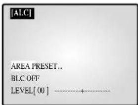
- Bb6cpHtE NyHKT AREA (OBJIACTb) c NOMOJIbIO NOBOPOTHOKoIEcNka HnKaMHTe KHOIky ENTER IIN Bb6opAp "PRESET..."(IPO YMOJUAHNIIO "USER" (YCTAHOBKA IOJIB3OBATEJIA).
Bb6epHTe“PRESET...”cIIOOMOuio IOBOPOTHOro KOIECNKa HnAKMNTC KHOIIKY SET IJIy Bb3OBA CInyIOHcero OKHa. KOMNCHaIIH 3aIIHrO CBtA ByET NpHMChIbTcR K O6JIaCTH (Oblactm) CO 3HaHEHHM, yCTAHOBJEEHHBMN HITOTOBHTJEJM.
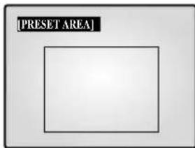
HaKMHTe KHOIIky MENU, TIO6bI BepHyTbcK IpeMbIyMeMy MeHIO.
-Bb6epHrE“USER”cHOMOIOBIOHOBOPOTHOKOLeCNKa HnKaMHTe KIOIky SET bIB3OBa cJeDyIOIero OKa.
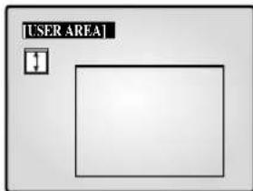
OTpyIpyTe pa3Mcpe NOBcTHKaTH C HOMOIIbIO NOBOPoTHOrO KOIEChka HaKmnte KHOINky ENTER IaIpeYIpHpOBKn pa3epa IIO TropnOHTaII. Ha eKpaHe OT6pa3ntc“
OTpcryIHPoBaP a3Mcp n0rpoHOrTaJIc HOMOIIbIO NOBOPHOKOJIeCKa,HaKMITE ENTER. 3aTeM MOKHO 6yET OTpeRyIHPoBaTIOLOKeHHe IO BepTKaJIH,Ha EKpaHE OTO6paHTCn“
OTperyIHPoBaB NOJoxKeHHe C NOMOIOHO NOBOPOTHO KOJIeCnKa, HAKMHTE ENTER. 3aTeM MoKHObEyIe TPERyIHPoBaTb NOJoxKeHHe No rOpH3OHraH, Ha 3KpaHc OTo6pa3HTc"
IOrperyHnPOBaB NoIOKHeHc HOMOJIbIO NOBOpOTHO KOJIeCNKa, HAKMITE ENTER.HAcTPOKa OBJACTN 3aBepHHeHa.HaKMITE KHOIKY MENU, YTO6bI BepHyTcK N IpEJIduIyMeMy MeIO.
- BLC (KoHcHcHnHa 3aHrero cBtA): KOrTa npaMeTp BLC yctAHOBJIe H 3haueHHe "ON" (BKJI),ФуHKIIa K3C 6yIeT IprHmCHHTbck KO BCem OblactTm,ycTaHOBJIeHHbIM B IOITMeHIO AREA (OBJACTb).KOrJa 06BeKT Hmeet JRPKe ofoHOBOe OCBeIeHne, OH BBIJIaHT Ha MOHITOpE TcMHbIM H3-3a HauINHra 3aIHcHro CbTeA.ДЯ pa3peHcHnA ToTn PpO6JIcMbHcNToL3yIteФyHKIIIO K3C,ToTla 6byT IIIOYATbCe N3O6paKeHHn6e 3aTeMHeHH.
LEVEL (YPOBEHB): YPOBcHb BbIXOIIHO HcOCHHaJa MoKHO yCTaHOHITb B IIpeJeaXoT " -9" to +9". Bb6epHTe NHyKT "LEVEL [00]" c IOMOIIbIO NOBOPOTHO KJIecKa H NaKMITE KONIKY ENTER IINMeHeHHa NapAMETpa. YTo6bl COxpaHITb HaCTpoHKy, HAKMITE KONIKY ENTER IocJIe IN3MeHeHHa NapAMETpa.
MANUAL....YcTaHOBka OTKpbTnAaKpTnH npHoBOJ dHaeppaMbl BpyHYIO.
- Bb6epHTe "MANUAL..." c NOMOIIIO IOBOPOTHO KOJIecnKa HAKMITE KHOIIky SET IIA BbIOBa CJeIyIOJero OKHa.
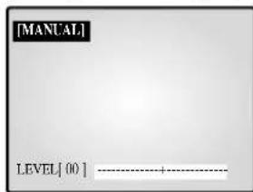
- YcTaHOBHe 3HauHHe C HOMOJIbIO NOBOPoTHOrO KOJIeCNKa. -HaXMMTe KHOIIky MENU, TTO6bI BEpHytbcr K IpeJbIyIeMy M
SHUTTER (3ATBOP)
-3Jecb MOKHO yCTaHOBNITc KOpocTb JINI 6bICTpORO 3JIeKTPOHHORO 3aTBopa, ABOTMATUHECKOTo MEJIIeHHORO 3aTBopa H ΦHKCnPOBAHHORo MEJIIeHHORO 3aTBopa.
-БыстbyлэйктpoHHьзВТВОМоКну yctaHOBHTb Ha 7 ckopoCTeH cnYcKa or 1/120(1/100) cek. no 1/10K cek. ABToMaTHupeckn MmIeHHь 3aTВОп nФИКСИРОBAHHь mclIeHHь 3aTВОр moKHo yctaHOBHTb Ha 12 ckopoCTe cnYcKa or X2 lo X128.
- MeIeHHa cKOpocTh 3aMeJIeT cKOpocTh cNycka 3aTBopa, 6laOaapra 3tOMy H3o6paJKeHHI Ipi CJIa6om OcBeIeHHN BbIJIaHT aPc. IIra ABToMATHUcCKOrO OIpCeJIeHHN OCBIIeHHOCTH N 3aMeIeHHN cKOpocTH cNycka 3aTBOPA B3ABHCMOCTH OT OCBeIeHHOCTN bIbepHTE ABOTMATNUeCKNI MeJIeHHbI 3aTBOP. IIra yctAHOBKn cKOpocTH cNycka 3aTBOPa BpyHiY0 bIbepHTe ΦIKCnPOBAHHbI MeJIeHHbI 3aTBOP.
- HcTa IocIe IyIKTo AUTO H FIX 6o3HaJOT KoJHecTBO coXpaHembIX IOJIeJ. YEm BblIe KOJHecTBO, TEm MeJIeHHee cTAHOBHTCCKOPoCTb CNYcKa 3aTBopa. NtOMy BoJIee YnCTbIMN IOnyAHTC HIO6paKeHH HeIOBHKHbIX O6bEKTOB. JBNKyuHecr O6bEKTbMOTY NIOJYHHTCBc CMA3aHHBMN.
- YcTaHOBka 3NaueHnB MeHIO SHUTTER (3ATBOP) HauKMHTe KhoNkY ENTER nHaCTpoHN 3NaueHn. BbI6cpHTe 3NaueHnC c NOMOnIIbHO NOBOpOHOro KOJIecNka HauKMHTe KhoNkY ENTER IIu coXpaHeHH IaPaMeTpa.OFF '1/120(1/100)'1/250'1/500'1/1000'1/2000'1/4000'1/10K' OFF AUTO X2 AUTO X4 AUTO X6 AUTO X8 AUTO X12 AUTO X16 AUTO X24 AUTO X32 AUTO X48 AUTO X64 AUTO X96 AUTO X128' OFFFIX X2'FIX X4'FIX X6'FIX X8'FIX X12'FIX X16'FIX X24'FIX X32'FIX X48'FIX X64'FIX X96'FIX X128.
WHITEBALANCE (BAJIAHC BEJIOO): ATW,AWC., MANUAL...
IIINBKKHHeHHFyHKHH6aHaHc6eJoo6eJIbTeToHa BblIJIaIT cCTeTBEHHO He3aBHCNOOTIBeTOBOI TeMnepaTybIBTex HIN INHBIX ycIOBHXOCBeEHHOCTH.
ATW:KoHTpoJIb3aH3MeHHEmBUBeTOBOI TeMHePaTye COOTBeCTByIOIIapeyINpOBKa 6aJIaHa 6eJoro.
- AWC: OДнOKрathЯн HabTpoKa 6aJaHca 6eJIoR B COOBetCTBnC
- IIeTOBOI TeMnepaTyPoH N 3aTeM NoJIePkaHInc 9ToTOrO NaPaMeTpA.
- KoIIa OTKpbIIO OKHO AWC, HOMecHTte JInct 6eJIoN 6yMaHn IpepI
- KaMepoH N HaxKMHTe KHOIIK SET.
MANUAL...:Bb6epHTe“MANUAL”cIIOOMOIIbIOIOBOPOTHOKOJIeCHKaHaKMMTE KHOHky SETIIBHOBA CJIeJyIOIero OKHa.3aTeM MOKIIHO Bb6paTb peKHM 3200K,5600K HINUSER (IOJIb3OBATEJCKN) HycTaHOBHTb BaJIaHC 6eJIoro BpyHyIO B3aBHCHMOCTH OT TeKUHx YCBHn OCBeIeHHOCTH.

-3200K:YctaHOBKaIbTeBOB TeMnpepaTypbHa 3200^
-5600K:YcTaHOBkaIbETOBOnTeMHePaTypbHa 5600°.
- BbI6cpNTc NyIKT "OFF[USER]" (BbIKJI [IOJIb3OBATEJBCKN]) IJI BAIBOBA CJJeDyIOIeO OKHa. aKMHTc ENTER, a 3aTeM BbI6epNTe COOTBeTCTByIOIe 3HaueHnRA RED (KPACHOTO) H BLUE (CNIHEO) IJI yCTaHOBKn IBeTOBOI TeMHePATypbI BpyHyIO.
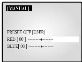
HaKMHTe KHOIIky MENU, TIO6bI BepHyTbcK IpeMbIyMeMy MeHO.
SPECIAL...(CIIIEHAAJIbHbI E HACTPOIKN)
- Bb6epHrTe "SPECIAL..." c NOMOIIbIO NOBOPOTHO KOJIeCHKa HAKMITE KHOIIky ENTER 1Ia BBIOBa CJeIyIOIEoOKHa.
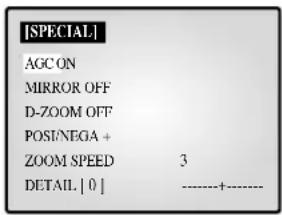
- AGC: KIOOeHHe/OTKIOOeHHe ΦyHKIIIN AGC (aBToMaTHueckKOrO yIpaJIeHHyCHJIeHHem).
- MIRROR: Pa3BOPOT IO TROP3OHTAJIN BbIXOJHbIX BNIEOCNHADIOB.
D-ZOOM:YcTaHOBKa KOeΦnIHHeHTa YBCJINCHNIIpH INIPOBOM yBEJIHIEHH. DaHHa CHCTema IIO3BOJHE T BbIIIOJIHrTb yBeJIHIEHne 10 pa3. - POSI/NEGA: YcTaHOBKa BbIXOJIHbIX BnDEOCnIHbIbHa O6bIHHbI HIN O6paTHbI BbIXOJI.
- ZOOM SPEED: YcTaHOBKa cKopocTH yBeJIuHeHHa.
-1:ДИNTcraOKOJO 17ceK.OTx1JIOx12(MHIMMaJIbHaIckopoCTb)
-2:IIITc0KOIO 10ceK.OTx1doX12(MeIeHnackopoctb)
-3:Длttсakolio6cek.otx1nox12(bctpaekopoctb)
- 4:ДиITсЯ кОJO 3 cek.OT x1do x12 (MaKcHMaJIbHaJ cKOpocTb)
- DETAIL: HactpoKa JpKocTH IOBepTKaJIH Irop3OHTaJIH.
FOCUS (ΦOKYCnPOBKA): ΦokycnpoBka
ycTaHaBJIINBaTeCB3HaeHeMe MF HNN ONEAF.
MF:PeKHMpyHOnfOKyCnPOBKNIO3BOJAEIHOIB3OBATEIO HacTpanBaTb fokyCnPOBky caMOMy.
ONEAF: PnHy yBéJHEnHH B CTOpOHy TEeOe6bEeKTHBa ABTOΦoKycnPbOBKa BbIIOJIHReTcR ToJIbKO OIN Pa3 NocJIe BBIOJIHeHnФyHKnn TEeOe6bEeKTHBa.
-BpeKHMNEONEAFBce npOHcxOHT aHaIorHNopeKHMpyHoi φokycnpoBKn, KOrJa o6bekTbI HeIOJIbnHbI, H aHaIorHNo peKHMy ABTOpOKcnpOBKn pRn yBeJIHHeHN B cTOpOHy TeJeo6bekTHBa.
MOTION DETECT... (OBHAPYKEHNE IBHXEHHA):
ΦyHKIIHgOBHApYKeHHN JBHXKeHHN HcNoJIb3yTeC JnOgOBHApYKeHHN JBHXKeHHN O6BeKtA. PnB BKIOHeHHN 3TOH ΦyHKII NIOBHTCR BO3MOXHOCTb OBHApYKeHHN IpcJbHXKeHHN IOCTopoHHero JINHc BA HOHHOE BpEMH II.
Bb6epHre "MOTION DETECT" c HOMOIIbIbIO IOBOPoTHOrO KOJIecNka H HAKMHT KHOIIky ENTER 118 Bb3OBa CJIeIyIOIeRIO OKHa. I0 BbHIOJIHeHHH HAcTPOHKn HAKMHTe KHOIIky MENU, VTO6bI BeHyTBcK IIpeIbI dyIeMy MeHIO.
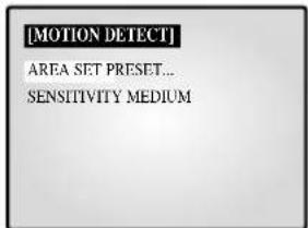
-
AREA SET: YctaHOBka o6laCTH 3KpaHa, B KOTOpN pIMMeHcTeT aATuHK DnHexHeHH.
-
PRESET...(IIO YMOLJUHNO)
Bb6epHrTe“PRESET"cIHOOMOJIbIO NOBOPOTHOKJOeCHKa HAKMITE KHOIIky SET IIIBbIOBA CJIeyIOJcero OKHa. FyHKIN8 0bHApUxKeHHJ BnIXKeHH6ByET IIPHMHeHTbcR K OBJaCh (OBJaCTM) B IIpeJIax paMKH.
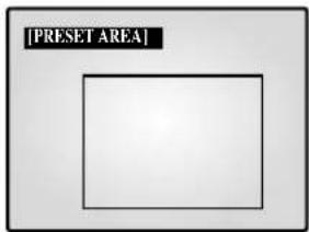
HaKMHTe KHOIky MENU, TIO6bI BepHyTbcK IpeBldyMeMy MeHO.
-USER...HACTPOKAIOJB3OBATEJIA
I Bb6epHrTe "USER..." c NMOUIIO NOBOPOTHO KOJIechnKa HAnKMnTE KHOIIky SET IINBbIOBA cIeyIOIOE OKHa.
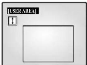
OTpyyhyrpea3mepnoBepTKaHc nOMOIIbIO NOBOPoTHORO KOeCNKa HaxMHTc KHOIky ENTER IIN peryynpOBKn pa3Mcpa II IOropHOHTaII.Ha eKpAne OTO6pa3HrC“
IOrpEryHpyHre pa3Mep No rohpOHTaHc NOMOIO HOOBOPOTHO KOJIeCHKa HaxKMHTe KHOINy ENTER npeyHpOBKn IOJOKeHHN HoBepTKaHN.HaekpaHe oTo6paHrTc“
IOrpyHpyHrnoIOJoxKeHHnOBePTHKaJIHcHOMOuHbHO HOBOPOTHOKoJIecNkAHNaHXMHTe KHOINKy ENTER IpyHHPoBKNIOJIOKeHHnIOrOpH3OHraIH.HaKpaHe OTO6pa3HTcR “□”
OtperynoBabNoToxKeHn No rup3oHTaHc nmoHIOHOBOPOTHoro KoIeChKa,HaKMHTe ENTER. HactpoKa OBJACTN 3aBepeHeHa.HaKMHTe KhoIKy MENU, TRObI BepHyTbcK InpelblnyMcHIO.
SENSITIVITY: YctaHOBKa YyBCTBnTeJIbHOCTIaTnKa JbNKeHHBA3haHHe LOW (HN3KA), MEDIUM (CPEIH) HIN HIGH (BbICOKA).
4. HACTPOIKA CNTEMBI
B 3TOM MEHIO MOKHO H3MeHHb InapaMeTpbl ALAM (TPEBOTA),
RECORD (3AINICb), HIDDEN CAMERA (CKPbITAR KAMEPA). SEQUENCE (IOCJIIEOBATEJIbHOE IIPEKJIIOYEHNE).SYSTEM ID (KOJ CNTTEMbl), PASSWORD (IIAPOJIb) H LANGUAGE (I3bIK). BbIepeHrBE MEOH OACTPOIKN "4. SYSTEM SETTING" (HACTPOIKCA NCTEMbl) c IMOOIIIO IOBOPOTHO KOIEcKAn HaxMHTe KONky ENTER ⅡI BbIOBA CJeIyIOIero OKHa.
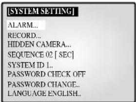
- BbI6epHTe IyIKT C IOMOJIbIO IOBOPOTHO KOJIecHcA HHaKMHTe KhoIky ENTER 13MHeHHaPametpa.
- NMaMeHHTe NapaMeTp c NOMOJIbIO IOBOPOTHOKoJIecHKa HauKMHTe KhoIky ENTER nIa coXpaHeHHa napaMetpa.
- IIO BbIOJIHeHHBcEx HAcTPOeK HaXMITE KHOIIky MENU, TTO6bI BepHybC B MEHIO HACTPOIKN.
ALARM... (TPEBOFA)
- Bb6pcntc "ALARM" c IOMOIOI IOOBOPOTHO KOJIeCHKa HHaKMHTc KHOIKY ENTER IIIBB3OBA CJeDuIOE OKA
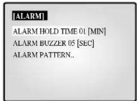
ALARM HOLD TIME (BPEM COXPAHEHNA TPEBOH) BPEM COXPAHEHNA TPEBOH - 3TO BPEM, B TeueHne KOTOPORO coxpaHaeTcra TpeBOHa. BpEM BBaun CHHaJa MOKHO yTaHOBHTb Ha 5 ccK., 15 ccK., 30 ccK., 1 MHH., 3 MHH., 5 MHH., 10 MHH., 20 MHH., 30 MHH AUTO (ABTO). PnBb6ope AUTO peKHM TpeBOH byeT coxpaHbTa cHa BpEM BBaun CHHaJa TpeBOH.
ALARM BUZZER (3BYKOBOI CNTHAJ TPEBON)
IIpH BO3HHKHOBCHH TcBOH pa3dactc 3ByKOBO CHHaI.
IPOIOJIKHTeJIbHOCTb CnIHa MoXHO yCTaHOBTb Ha 5 cek.,15 cek,
30 cek.,1 MHI.II IN OFF (BbIKJI).IIpH BblOe IyIKTa OFF
3ByKOBOI CnIHAI 3ByAHTb He dyJeT.
Bb6epHre "ALARM PATTERN" (IIABJIOI TPEBOTN) c IOMOIOI IOBOPOTHOKOJIeCNKa HnKMMTe KHOINKY ENTER IINBA BtBa CJJeYIOJIero OKHa
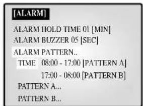
BIByX IIIa6IOHax MOxHO BbIpaTb BpeMBAIOOeHHN BbIKIOOeHHpeKHMa TpeBOH.
IpiBbl6ope PATTERN A (IIASJIOHA A) BpeMa B PATTERN B (IIABJOHE B) 6yJeT ABTOMATueeCKN H3MeHeHO.
Bb6epHTe PATTERN A c nOOMUHIO NOBOPOTHO KOJIeCHKa HnKMTe KHOky ENTER IIBI Bb3OBA CIEyHOUIero OKHa.
KOBOPETOHOHNSOSSAFEL
7. IocJeIOBaTeJIbHoe IpeKJIHOeHne KaHaJIOB
- Bébop oT 01 do 30 cek.
8. IIOBTop co6bIITH
-TpeBora/ДВиЖeHHe/NotepKaHaJIa:MaKc.16 KaIpOB Ha KaJbI KaHaJI
-3BOHOKBIBepb:MaKc.8KaIPOB
9.CiHcok
TpeBora/DbNKeHHe/IOTepe KaHaJa:MaKc.50
-3BOHOKBπBCpb:MaKc.8
10. Pa3deJenHbI 3Kpan
-ПОЛнь,4,8,9,16,yBJIeHHeHHbI,PIP
11. PazpeiHne H no roH3oHTaJIn
14. BctpoeHHbIe Yacbl
-±1MHHyTa/MecHnH MeHbIe
15. 9JT
- SMO-210TRN(P):ПJOCKAR 3JIT 21"
- SMO-150TRN(P): IIJOCKAR 3JIT 15"
16.ΓaδapntbI (ⅢxΓxB) (MM))
- SMO-210TRN(P) : 520 x 509 x 486
- SMO-150TRN(P) : 388 x 459 x 379
17. Bec:
- SMO-210TRN(P) : 28 Kr (6e3 ynaKOBKN)
32.5Kr(cynakobko)
- SMO-150TRN(P): 15,2 kT (6e3 yπaKOBKN)
18,5Kr(cyiaKOBKO)
18. Iorpe6eHne 3heprnn
- CM. 3THKETKY Ha 3aJHei IIaHeI MoHHTopa.
19. BnIeocHcTeMa
- SMO-210TRP/150TRP: TOJIBO BUNIEOCNCTEMA PAL
- SMO-210TRN/150TRN: TOJIbKO BnIEOCHCTEMA NTSC
YcTpaHHeHHeHnOJaIOK
PnHIOJIb3OBAHHN CHTeMbMOKET BO3HNKHyTb HEOKJdAHHa HEnoJaKa, INpBOaIIaK K c6oM B ee pa6ote. OHaKO B 60JIbHCTBe Clyaeb 3TH HeIOJIaIK N ABJHOcRc He3HaHTeJIbHIMn JIeKo ycTaPAHOTcR.
Jaiee npHbOaTc coBteIIO BO3MOxHOMy yCtpaHeHHo HEnoJiaOK.
Ocyctbyet ektpoHraHne
Y6eINrTeB IpaBn.IbHocTHIIOKIIHOHeHH HHypa K HCTO1HNkyIHTaHH.
PpOBepeTe HHyp HHTaHn.
Ha ekpahe He IpoBJIeTc H3o6paKeHHe.
IIPOBepTe coeHHHeHHa KAMepo, INHHaJIeKHOCTMa H BIIHHMM MOHHTOPOM.
He pa6oTaertanncb.
Y6eHITec, TTO K BXOJHOMy IOPTy BnDEoCHHaJa BNDEOMaHTofoHa H IOHOIHHTe.IbHOMy BbIXOIHOMy IOPTy BnDEoCHHaJa BNDEOMaHTofoHa JaHHOI CHCTeMbI IIpaBbIbHO IIcOeHHHe Ka6Cb.
Y6eHITecb,TOHaKaccety, BcTaBJIChHyIO B BIIeOMAIHHTOFOH,MOXHO BBIOJINHTb 3aIHNCb.
Y6eINTeB B IpaBHLbHocTH coJIHeHHB bIXoHO TPHTepHOrO IopTa 3aIHcN (REC) BNJeOMaHTHOHa JInTeJbHOI 3aHcN cTPHTEPHBIM DOIOJIHHTeJbHM IOTOM BNJeOMaHTHOHa (6- KOHTAKTHbIM IOIOJIHHTeJIbHbIM IIOPTOM BNJEOMAHTHOPOHA) TaHHOn CCHTeMBI npH 3aIHcN B peKHMe JInTeJbHO3aHHcN.
Hepa50taetBocnpOBBeHne
Y6eIHTecb,TOK BbIXOHOHOMy HIOpy BNIOEOCHHaIIa BHIOOMaHTHOPOHa H IOHOJIHHTe.HOBMO BYXoHOHOMy HIOpy BNIOEOCHHaIIa BHIOOMaHTHOPOHa JAAHOI OHCTeMBI IpaBnTbHO IOJCOeINHe Ka6eJIb.
Y6eHITecb,TOpeKHM OTo6paKeHHHaHHoH ChTeMbI ycTaHOBJIeH B peKHM BocPiOn3BCJeHHn HIn TpOHOrO 9kpaHa.
BpeKHe aBTOMaTHueckKOrO nocJeIOBaTeJIbHOrO nepeKIOUeHHaHApOB Hc3o6paKeHH
- Y6eHNTecb,TO 3KpaH pa6oTaert B pcKHMc pcaJIbHO rBpcMCHN.
IPOBepbTe IpaBnHbHOCTb yCTaHOBKN BpeMeHN BIOJMeHO "SEQUENCE" (IOCJIJEIOBATEJIbHOE IIPEEKJIOUHEHNE KAHAJOB) MEHO HACTPOIKN.
EcHHeNoTaJaKa coxpaHaTeC, 6oPaTHTeCb 3a NOMOIIIO K MecTHOMY TOPROBOMy IpeCTaBHTeIIO HIN B cepBnChbI ueHTp.
Пrimецане
EcHHeNoTaJaKa OTHocHcTc 3aHHbIO HIN BOCpOH3BeJeHHe BHcOMaHTHOPOHa, POBcPbTe TaKKe pa6Oy BHcOmaHTHOPOHa.
Памятka
SAMSUNG
Part No.: AA68-03275A-00
Printed in Korea