USER MANUAL FBS 43 B2 FLORABEST

natural_image
Black and white photo of a manual push tool with a mounted motor and base (no visible text or symbols)
PETROL GRASS TRIMMER FBS 43 B2
GB IE
PETROL GRASS TRIMMER
Translation of original operation manual
Read carefully before using machine!
SE
BENSINDRIVEN RÖJSÅG
Before reading, unfold both pages containing illustrations and familiarise yourself with all functions of the device.
FI
GB / IE Translation of original operation manual Page 1


2

natural_image
Three industrial tools or pumps with no visible text or symbols


natural_image
Two black mechanical components labeled 17a and 17b, with no visible text or symbols on the parts themselves.


natural_image
Close-up of a hand holding a metal pipe fitting with a numbered label (19), no visible text or symbols beyond the number.
natural_image
Mechanical assembly diagram showing a lever mechanism with a rotating component (no text or symbols)
natural_image
Mechanical assembly diagram showing a lever mechanism with a circular motion indicator (no text or symbols)

natural_image
Close-up of a mechanical assembly with a tool inserted, no visible text or symbols


natural_image
Close-up of a mechanical component with arrows indicating motion, no visible text or symbols
natural_image
Close-up of a mechanical component with three blades and a central hub, no visible text or symbols
natural_image
Close-up of a mechanical component with a numbered label (23) and rotational arrow, no readable text or symbols present.


natural_image
Black mechanical device with attached straps and a bag, labeled '8a 8b' (no other text or symbols visible)

natural_image
Person wearing a checkered shirt and holding two small objects (no visible text or symbols)

natural_image
Person wearing a checkered shirt with a belt buckle, no visible text or symbols
natural_image
Person wearing a checkered shirt and full-body harness, hands placed on chest (no visible text or symbols)

natural_image
Person wearing a checkered shirt and black safety harness, hands adjusting the belt (no text or symbols visible)

natural_image
Close-up of a mechanical component with a clamping tool, no visible text or symbols
natural_image
Close-up of a mechanical component with a metal rod and wires, labeled '8g' and numbered '1' (no readable text or symbols beyond labels)
natural_image
Close-up of a mechanical clamp or bracket assembly with a 8-hour time label (no readable text or symbols beyond the label)

natural_image
Person using a tool on a mechanical device with a compass and directional arrow (no text or symbols visible)
Contents
Introduction 2
Proper use 2
Package contents....2
Features 2
Technical details 3
Safety instructions....3
Handling....3
Safety equipment 4
Before use 5
Safety measures when handling the cutting blade .... 5
Initial operation....5
Assembly 5
Putting on the shoulder strap....6
Operation....6
Maintenance and Cleaning....7
Spare part orders 8
Storage and transportation....8
Troubleshooting guide 9
Warranty 9
Service 9
Importer....9
Disposal 10
Translation of the original Conformity Declaration ....10
PETROL GRASS TRIMMER FBS 43 B2 Introduction
Congratulations on the purchase of your new device. You have selected a high-quality product. The operating instructions are an integral part of this product. They contain important information about safety, use and disposal. Before using the product, familiarise yourself with all operating and safety instructions. Use this product only as described and only for the specified areas of application. Please also pass these operating instructions on to any future owner(s).
Proper use
Use with cutting blade: for cutting high grass and undergrowth with the 4-section cutting blade, or dense undergrowth and small woody plants with the 3-section cutting blade.
Use with line spool: for cutting grass and small weeds.
Any other use which is not expressly permitted in these operating instructions may damage the device and represents a serious risk for the user. Please make sure that you pay attention to the restrictions in the safety instructions Pay attention to the national regulations which may restrict the use of the machine. Any other uses of or modifications to the device are deemed to be improper usage and may result in serious physical injury. Not intended for commercial use.
PROHIBITED APPLICATIONS!
Due to the physical risk posed to the user, the device may not be used to perform the following activities: cleaning footpaths and as a shredder for shredding tree and hedge sections. Furthermore, the device may not be used to level elevations such as molehills. For reasons of safety, the device may not be used as a drive unit for any other devices. The user, not the manufacturer, is liable for any resulting damage or injuries of any kind.
Package contents
1 petrol grass trimmer FBS 43 B2
1 operating instructions
■ Open the packaging and carefully remove the device.
■ Remove the packaging material and packaging and transport locks (if present).
- Check to ensure that the package content is complete.
■ Inspect the device and accessories for transport damage.
■ If possible, store the packaging until the end of the warranty period.
Features
① Guide rail connecting piece
② Guide rail
3 Guide handle
4 Starter pull cord
⑤ Choke lever
6 Fuel tank
⑦ Fuel pump (primer)
8 Air filter housing cover
9 On/Off switch
10 Throttle control
⑪ Throttle control lock
12 Line spool with cutting line
13 Cutting line protective hood
14 Cutting blade protective hood
15 2 x M6 screws
16 Shoulder strap
17a 4-tooth cutting blade
17b 3-tooth cutting blade
18 Handle bracket
19 M6 handle screw
20 Drive plate
21 Pressure plate
22 Pressure plate cover
23 M10 nut (left-hand thread)
24 Oil/petrol mixing canister
25 Spark plug spanner
26 5 mm hexagonal key
27 4 mm hexagonal key
28 M6 handle screw
29 Air fi Iter
30 Spark plug connector
The cutting blade 17a/17and line spool d12 also referred to together as the cutting tool in the text.
Technical details
Engine type: 2-stroke engine, air-cooled, chrome cylinder
Engine output (max.): 1.35 kW / 1.8 hp
Cylinder capacity: 42.7 cm ^3
Engine idle speed: 2700 - 3400 rpm
Max. engine speed
with cutting blade: 10500 rpm
with line spool: 9000 rpm
Max. cutting speed with
cutting blade: 7850 rpm
with line spool: 6750 rpm
Ignition: Electronic
Drive: Centrifugal
Weight (tank empty): 8 kg
Line cutting diameter ∅: 43 cm
Cutting blade cutting
diameter ∅: 25.5 cm
Line length: 8.0 m
Line ∅: 2.0 mm
Tank size: 0.85 l
Spark plug: Champion RCJ7Y
Fuel consumption at
max. engine performance: 0.6 kg/h
Specific fuel consumption
at max. engine performance: 446 g / kWh
Noise and vibration data:
Noise measurement determined in accordance with EN ISO 11806-1.
The A-rated noise level is typically:
Sound pressure level L_FA : 96.3 dB(A)
Uncertainty K_pA : 2.5 dB
Sound power level L_WA : 110.3 dB(A)
Uncertainty K_WA : 2.5 dB
IMPORTANT!
■ Wear hearing protection!
WARNING!
Also reduce the risk due to vibrations, e.g. the risk of Raynaud's phenomenon, by taking frequent breaks and rubbing your hands together!
Operation
Vibration emission value q_n = 8.2 m/s^2
Uncertainty K = 1.5 m/s²
WARNING!
The vibration level specified in these instructions has been measured in accordance with the standardised measuring procedure specified in EN ISO 11806-1 and can be used to make equipment comparisons. The specified vibration emission value can also be used to make an initial exposure estimate. The vibration level varies in accordance with the use of the tool and may be higher than the value specified in these instructions in some cases. It is easy to underestimate the vibration load if the electrical power tool is used regularly in this manner.
NOTE
For an accurate estimate of the vibration load during a certain working period, the times during which the device is switched off or is running but not actually being used must also be taken into consideration. This can significantly reduce the vibration load over the total working period.
SafetyclutchInstructions
WARNING!
Please read all of the safety instructions. Failure to follow the safety instructions listed below can result in electric shock, fire and/or serious injuries.
IMPORTANT!
The device and packaging material are not toys! Children must not be allowed to play with the plastic bags, foil and small parts! Risk of suffocation!
Keep all safety instructions and other instructions for future use.
Handling
■ Wear close-fitting work clothes that offer protection, such as long trousers, safe work shoes, durable work gloves, a protective helmet, a protective face mask or protective glasses to protect your eyes and high-quality ear plugs or other hearing protection against the noise.
■ Only appropriately trained individuals and adults may operate, adjust and maintain the device.
If you are not familiar with the device, practice handling the device while the engine is off.
■ Ensure that screws and connecting elements are firmly tightened. Never operate the device if it is not correctly adjusted, incomplete or if it is not properly assembled.
■ Open the fuel tank slowly in order to allow any pressure which may have built up in the tank to dissipate. To prevent the risk of fi re, move at least 3 metres away from the refuelling area before starting the device.
■ Always hold the device with both hands. Your thumbs and fingers should encircle the handles.
■ Work posture: Do not operate the device in an uncomfortable position, when you are unbalanced, with arms fully stretched or with only one hand.
■ Always ensure that you have a solid and firm stance.
■ Always use the enclosed shoulder strap.
■ Always ensure that the handles are dry and clean and that no petrol mixture is present.
Do not use the device if spectators or animals are in the direct vicinity. Maintain a minimum distance of 15 metres between the operator and other persons or animals when trimming. Maintain a minimum distance of 30 metres between the operator and other persons or animals when mowing down to the ground.
- Check the area prior to starting work for objects such as metal parts, bottles, rocks, etc. which can be fl ung away and injure the user.
■ Adjust the line coil to the desired length. Avoid contacting small objects (e.g. rocks) with the line coil,
■ Always hold the line coil on the floor when the device is in operation.
■ When trimming on a slope, always stand at a lower level than the cutting tool. Never cut or trim on an icy, slippery hill or slope.
■ Before starting the engine, make sure that the line coil is not in contact with any obstacles.
■ Do not use the device if it is damaged or defects are visible.
■ Always trim and cut using the high speed range. Do not let the engine run at a low speed when starting mowing or trimming.
If the device accidentally comes into contact with a solid object, immediately turn off the engine and inspect the device for damage.
■ Switch the device off before you put it down.
■ Always turn the engine off before working on the cutting tool.
IMPORTANT!
■ Do not touch the exhaust.
■ Only use the device for the intended purpose, such as lawn trimming and mowing activities.
■ Do not use the device for long periods, take regular breaks.
■ Do not operate the device under the influence of alcohol or drugs.
■ Only use the device if the appropriate protective hood has been installed and is in good condition.
■ Any changes to the product may risk personal safety and void the manufacturer's warranty.
■ Never use the device near highly flammable liquids or gases, either in closed rooms or in the open. This may result in explosions and/or fire.
Do not use any other cutting tools. For your safety, only use accessories and additional devices that are indicated in the operating instructions. The use of parts other than those recommended in the operating instructions, or other accessories, can put you at risk of injury.
Safety equipment
The relevant plastic protective hood to operate the cutting blade or line must be installed when working with the device in order to prevent objects from being slung away.
WARNING!
■ Never mow/trim while other individuals, especially children or animals, are in the vicinity.
- Maintain a safety distance of 15 m. Immediately turn off the device if this distance is not maintained.
IMPORTANT! RISK OF POISONING!
■ Exhaust gases, fuel and lubricants are toxic. Exhaust gases must never be inhaled.
Explanation of the symbols on the device!

Warning! Read the operating instruction before use!

Wear hearing protection!

Wear protective glasses!

Wear safe work boots!

Wear work gloves!

Wear head protection!

Protect the device against rain or moisture!

Beware of fl ung objects!

Turn the device off and remove the spark plug before performing any maintenance work!

A distance of 15 metres must be maintained between the machine and third parties!

The cutting tool continues running after it is turned off (cutting blade/cutting line)!

Important, hot parts. Keep a safe distance away!

Add a little grease after every 20 hours of operation (gear grease)

Beware of recoil!

Attention - petrol is highly fl ammable! Risk of explosion! Do not spill fuel!

Attention! Risk of suffocation!

Caution! Toxic CO vapours!

Do not use the device in closed rooms!

Caution! Risk of injury from rotating cutting blade!
Keep hands and feet away!

Sound power level L_WA data in dB.

Petrol/oil mix ratio information.

Note! Left-hand thread.

Note! Assemble guide handle.

Max. rotation per minute.
WARNING!
- Petrol is highly flammable. Only store petrol in the containers provided.
■ Only refuel out in the open and do not smoke.
■ The filler cap must not be opened and refuelling must not take place while the engine is running or when the device is hot.
- Do not attempt to start the engine if the petrol has overfl owed. Instead, remove the device from the area polluted by petrol. Do not attempt to restart the device until the petrol fumes have dissipated.
For reasons of safety, the petrol tank and filler cap must be replaced if they are damaged.
Before use
IMPORTANT!
■ When mowing/trimming, always wear non-slip safety boots and proper safety clothing, such as work gloves, a protective helmet, a protective mask or protective glasses and hearing protection.
- Check the area in which the device is to be used and remove any objects that may be caught and slung away.
Before use and after dropping or other impacts, always visually inspect the device to check whether the cutting tool, mounting bolts and the entire cutting unit is damaged. Worn or damaged cutting tools and mounting bolts must be replaced.
■ Always perform a visual inspection prior to use to check whether the cutting tool is worn or damaged. To prevent imbalance, worn or damaged cutting tools and mounting bolts may only be replaced in sets.
Limit the noise development and vibrations to a minimum!
■ Only use devices that are in good condition.
■ Maintain and clean the device on a regular basis.
■ Adapt your working method to the device.
■ Do not overload the device.
■ Have the device inspected if necessary.
■ Switch the device off when not in use.
■ Wear gloves.
Safety measures when handling the cutting blade
The device may cause blindness and injuries to bystanders. Maintain a minimum distance of 15 metres in all directions between the device and other persons or animals.
- Do not use the device if any of the cutting blade accessories have not been properly installed.
The cutting blade can be catapulted away from objects with force. This can lead to arm or leg injuries. If the device comes into contact with a foreign body, immediately shut down the engine and wait until the cutting blade has come to a complete stop. Check the cutting blade for damage. Always replace the cutting blade if it is bent or torn.
The cutting blade forcefully slings away objects as well as soil. This may cause blindness or injuries. Wear eye, face and leg protection. Always remove objects from the work area before using the cutting blade.
The cutting blade continues to run down once the throttle lever has been released. A cutting blade that is running down to a stop may cause cutting injuries to you or bystanders. Turn the engine off and make sure that the cutting blade has come to a complete stop before performing any work on the cutting blade.
Initial operation
Assembly
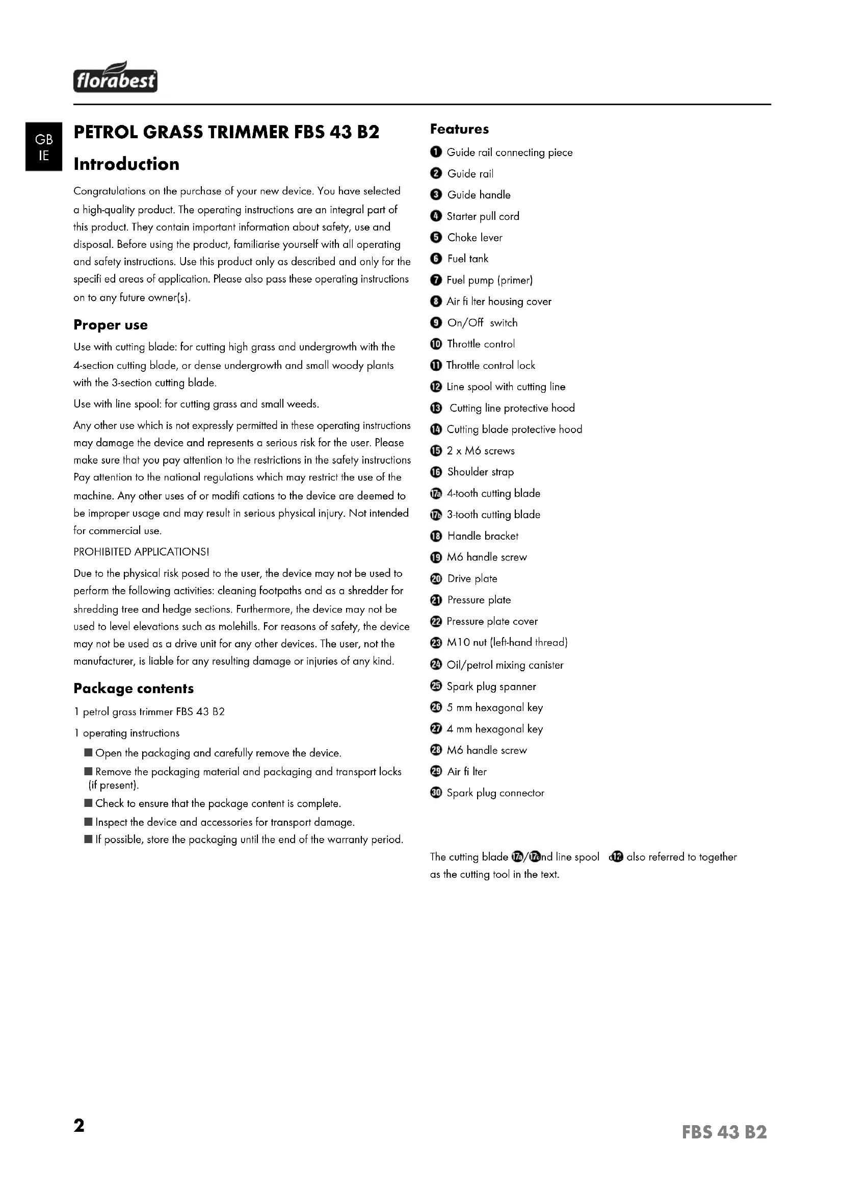
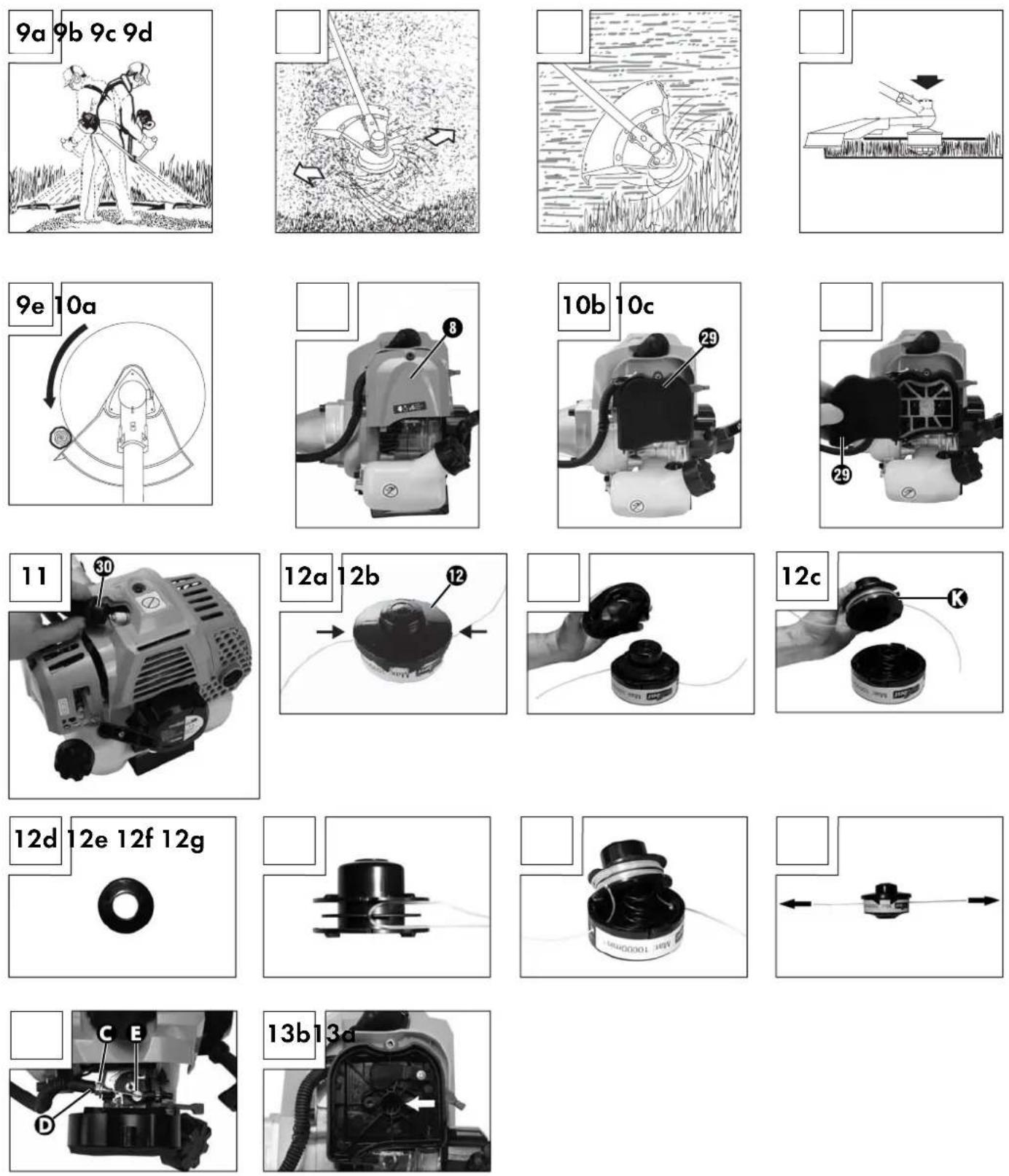
Assembling the guide handle (Fig. 3a - 3c)
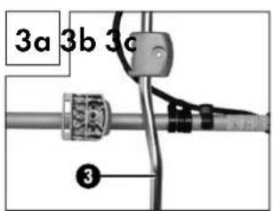
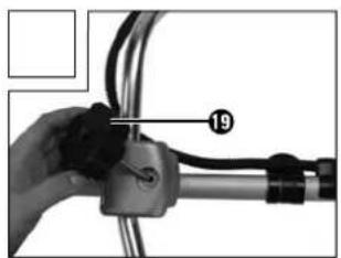
■ Assemble the guide handle ③ as shown in figures 3a - 3c. The guide handle ③ must be installed as displayed in fi gures 3a - 3c. Only tighten the handle screw ⑲ once you have adjusted the shoulder strap ⑬ the optimal operating position (see "Putting on the shoulder strap/adjusting the cutting height" chapter).
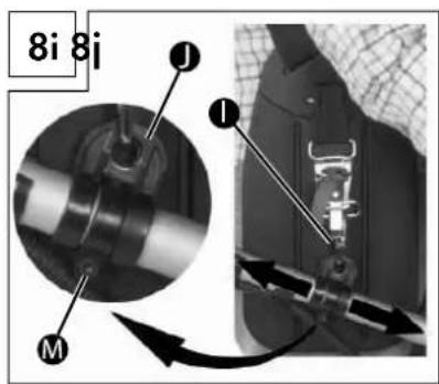
To adjust the guide handle 3 the correct distance from the body and to ensure that there is sufficient distance between the engine and yourself, loosen the two screws on the underside of the guide handle 3 see fig. 8j).
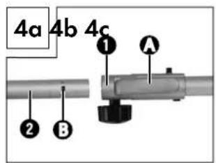
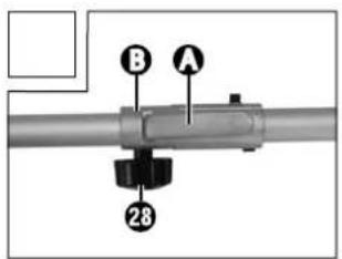
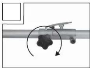
Assembling the guide rail (4a - 4c)
Press the locking lever A and slide the guide rail 2 (see fig. 4a) into the guide rail connecting piece 1. Make sure that the drive shafts inside the guide rail 2 slide into each other, lightly turn the line spool 12 he cutting blade 17a/17b if necessary. The locking lever hook A must engage with the slot B. Tighten the handle screw 28 as displayed in figure 4c.
Assembling the cutting blade protective hood
WARNING!
The cutting blade protective hood 14 must be assembled when working with the cutting blade. The cutting blade protective hood 14 is attached to the guide rail 2 using 2 screws 15 s displayed in figure 5.
Installing/replacing the cutting blade
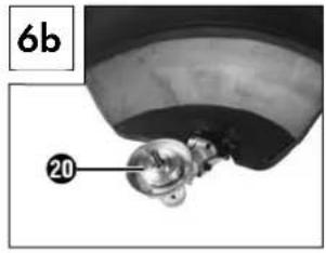
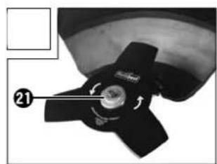
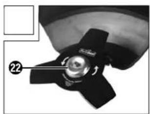
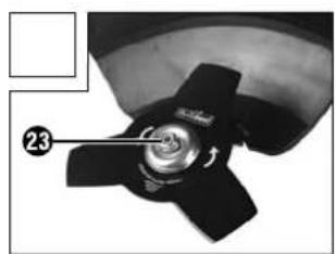
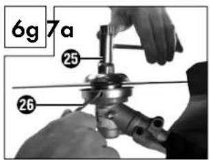
■ Install/replace the cutting blade 17a/17b as displayed in figures 6a - 6g.
■ Lock the cutting blade 17a/17b to the drive plate (see fig. 6c).
■ Insert the pressure plate via the splined shaft thread (see fi g. 6d).
■ Attach the pressure plate cove ^22 (see fig. 6e).
- Locate the drive plate drill hole, align with the underlying groove and lock with the enclosed hexagonal key 26, now tighten the nut 28 with the spark plug spanner 25.ee fi g. 6f + 6g).
NOTE! Left-hand thread!
The cutting blades 17a/17b are delivered with plastic protective caps. These must be removed prior to use and reattached when not in use.
IMPORTANT! SHARP EDGES, WEAR PROTECTIVE GLOVES
■ ATTENTION! Assemble the cutting line protective hood 13 on the cutting blade protective hood 14
The cutting line protective hood 13 must be assembled when working with the cutting line. The cutting line protective hood 13 assembled as displayed in figure 7a.
■ Ensure that the cutting line protective hood 13 is correctly engaged. A blade F located on the inner side of the cutting line protective hood 13.ee fi g. 7a). This is covered with a protective sleeve (Gee fi g. 7a).
■ Remove the protective sleeve before starting work and reattach after completing your activities.
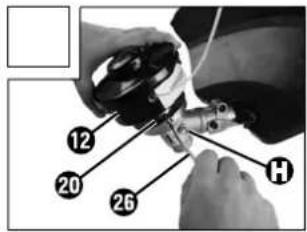
Installing/replacing the line spool
■ Install/replace the line spool ^12 as displayed in figure 7c.
- Locate the drive shaft drill hole ^20 align it with the underlying groove and lock it in place with the hexagonal key ^26 included, now screw the line spool ^12 into the thread.
NOTE! Left-hand thread!
Putting on the shoulder strap
NOTE
The following adjustments can be made to make sure that you can work without becoming fatigued. The settings may vary depending on your body size.
■ Before starting work, adjust the shoulder strap and the handle to your body size.
■ Balance the petrol-driven scythe with the installed cutting tool so that the cutting tool hovers just above the ground without touching the petrol-driven scythe with your hands.
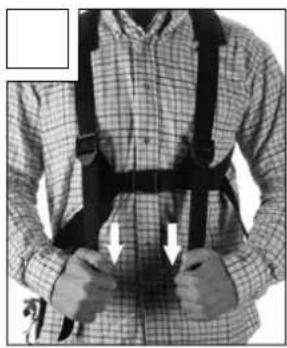
1.) Put on the shoulder strap and connect the two shoulder strap parts until they lock (see fi g. 8a - 8b).
2.) Pull on the shoulder strap, as displayed in 8c, to move the shoulder strap to the centre of your body and adjust the upper body girth accordingly.
3.) Now pull on the two shoulder straps, as displayed in figure 8d, to tighten them.
4.) To set the correct position of the petrol-driven scythe on the shoulder strap, pull on the belt as displayed in figure 8e.
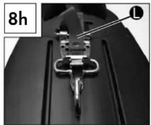
5.) Hook in the carabiner (see fi g. 8f - 8h) and secure it with the red strap on the quick release mechanism.
6.) Now pick up the petrol-driven scythe and hang it in carabinen using holder as shown in figure 8i. The bracket can also be released and shifted using a screw in order to set the best possible position of the petrol-driven scythe.
7.) The guide handle ③ can now be adjusted using 2 screws N in the underside to set the perfect position of the guide handle ③.
Setting the cutting height
- Put on the shoulder strap6 as displayed in figure 8a - 8c.
■ Hook the device into the shoulder strap (see fi g. 8d).
■ Set the ideal working and cutting position using the various strap adjusters on the shoulder strap (see fi g. 8e).
■ Perform a few circular movements without starting the engine in order to find the ideal shoulder strap length (see fi g. 9a).
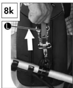
■ The shoulder strap is equipped with a quick release mechanism. Pull on the red strap ⬆ you have to release the device quickly (see fi g. 8k).
IMPORTANT!
■ Always use the shoulder strap when working with the device. Put the strap on as soon as you have started the engine and it is idling. Turn off the engine before removing the shoulder strap.
Fuel and oil
IMPORTANT!
■ Do not use a fuel mix that has been stored for over 90 days.
Recommended fuels:
■ Only use a mixture of unleaded petrol and special 2-stroke engine oil. Mix the fuel mixture in accordance with the fuel mix table.
■ Pour the correct amount of petrol and 2-stroke oil into the enclosed mixing canister (see fuel mix table). Then shake the canister well.
Fuel mix table
Mixing process: 40 parts petrol to 1 part oil
Petrol 2-stroke oil
| 1 litre 25 ml | |
| 5 litre 125 ml | |
Operation
IMPORTANT!
■ Please pay attention to the statutory provisions in the noise protection regulations.
Before starting the device, check for:
■ Tightness of the fuel system.
■ Flawless condition and completeness of the protective equipment and cutting equipment.
■ Firm position of all screw connections.
■ Smooth running of all moving parts.
Starting when the engine is cold
IMPORTANT!
■ Never allow the starter line to snap back. This may result in damage.
- Fill the tank. (see also "Fuel and oil" section).
2.) Press the fuel pump⑦ (primer) 6 times.
3.) Turn the on/off switch⑨ to "1".
4.) Set the choke lever 5 to "|n.
5.) Hold the device firmly and pull out the starter pull cord to the point of first resistance. Now quickly pull the starter pull cord The device starts.
6.) If the engine does not start, repeat steps 4-5.
7.) Once the engine has started, press the throttle control ^10 to release the auto choke.
If the engine does not start after several attempts, read the "Troubleshooting guide" section.
IMPORTANT!
■ Always pull the starter pull cord 4 out straight. Hold the starter pull cord handle firmly 4 when the starter pull cord 4 extracts.
Never allow the starter pull cord 4 to spring back.
NOTE
At very high ambient temperatures it is possible that even a cold engine has to be started without using the choke!
Starting when the engine is hot
(The device has been turned off for less than 15-20 minutes)
1.) Turn the on/off switch⑨ to "I".
2.) Set the choke lever 5 to "|1.
3.) Hold the device firmly and pull out the starter pull cord to the point of first resistance. Now quickly pull the starter pull cord The device should start after 1-2 pulls. If the device has not started after 6 pulls, repeat steps 1-7 under "Starting when the engine is cold".
Turning the engine off
Emergency stop sequence
If the device needs to be stopped immediately, turn the on/off switch to "0".
Normal sequence
■ Release the throttle lever 10 and wait until the engine has switched to its idling speed. Then turn the on/off switch 9 to "0".
IMPORTANT!
■ The cutting blade must be stationary when the engine is idling. If the cutting blade is rotating adjust the carburettor!
Optimal working procedures
Before using the device, practice all the operating techniques (see fig. 9a-9c) while the engine is switched off.
Extending the cutting line
To extend the cutting line, run the engine at full speed and tap the line spool 12 on the floor. The line extends automatically. The blade on the cutting line protective hood 13 shortens the line to the permitted length (see fig. 9d).
IMPORTANT!
Lawn/grass/undergrowth remains get caught under the cutting blade protective hood 14.
■ Remove the remains using a scraper or similar item when the engine is switched off.
Various cutting methods
Trimming/mowing (cutting blade or line spool)
■ Swing the device in a sickle-like mowing movement (see fig. 9a).
- Hold the cutting tool parallel to the floor and adjust the desired cutting height.
Low trimming (with line spool)
■ Hold the device over the ground at a slight angle (see fi g. 9b). Always cut away from the body. Never pull the device towards you.
Short mowing (with line spool)
■ Short mowing removes all the vegetation down to the ground. Angle the line spool 30 degrees to the right. Adjust the handle to the desired position (see fig. 9c).
Cutting against trees/fences/foundations (with line spool)
NOTE
The line will quickly wear or fray if it comes into contact with trees, rocks, walls or foundations. The line will break off if it strikes fence mesh.
IMPORTANT!
Do not use the device to remove any objects from footpaths, etc.! The petrol-driven scythe is a powerful device and small rocks or other objects can be catapulted 15 metres or more and cause injuries or damage to cars, houses and windows.
Seizing
Immediately turn off the engine if the cutting tool becomes blocked. Remove all grass and scrub from the device before restarting the device.
Prevent kickback
When working with the cutting blade there is a risk of kickback if it strikes against solid obstacles (tree trunk, branch, tree stump, rock or the like). This will result in the cutting tool being catapulted back against the direction of rotation. This may lead to the loss of control of the device. Do not use the cutting blade near fences, metal posts, boundary stones or foundations. To cut small woody plants, position the device as displayed in fig. 9e in order to prevent any kickback.
Maintenance and Cleaning
Cleaning
NOTE
■ Clean the device thoroughly after every use.
■ Always turn the device off before performing any cleaning work and remove the spark plug connector.
■ Clean the device regularly with a moistened cloth and a mild detergent. Make sure that no water can penetrate into the device interior.
Replacing the line spool/cutting line
1.) The line spool must be removed as described in the "Installing/ replacing the line spool" section. Compress the line spool ⑫ (see fi g. 12a) and remove one half of the housing (see fi g. 12b).
2.) Remove the spool discK from the line spool housing (see fig. 12c + 12d).
3.) Remove any remaining cutting line.
4.) Fold the new cutting line in the centre and insert the resulting loop into the spool disc recess (see fig. 12d).
5.) Tightly wind the line in a counter-clockwise direction. The spool disc separates the two halves of the cutting line (see fig. 12e).
6.) Hook the last 15 cm of the two line ends into the opposite spool disc line holder (see fig. 12f).
7.) Feed the two line ends through the metal eyelets in the line spool housing (see fig. 12f).
8.) Push the spool disc into the line spool housing (see fig. 12f).
9.) Re-connect the two halves of the housing.
10.) Give the two line ends a quick and vigorous tug to remove these from the line holders (see fig. 12g).
11.) Cut any excess line back to about 13 cm. This reduces the load on the engine when starting and warming up.
12.) Re-install the line spool (see "Installing/replacing the line spool" chapter). Skip points 3-6 if you are replacing the entire line spool.
Air fi lter maintenance
Contaminated air filters reduce the engine output due to low air supply to the carburettor.
Regular inspection is essential. The air fi lter29 must be inspected after every 25 hours of operation and cleaned if necessary.
The air filter must be checked more frequently if the air is dusty.
1.) Remove the air filter housing cover⑧ (see fig. 10a).
2.) Remove the air fi lte ^29 (see fig. 10b + 10c).
3.) Clean the air fi lte29 by tapping or blowing it out (with compressed air).
4.) Assembly takes place in reverse order.
IMPORTANT!
■ Never clean the air filter with petrol or flammable solvents.
Spark plug maintenance
1.) Remove the spark plug connector30 (see fig. 11a).
2.) Remove the spark plug using the enclosed spark plug spanner ^25 .
3.) Assembly takes place in reverse order.
Electrode gap = 0.6 mm (distance between the electrodes between which the ignition spark is generated). Tighten the spark plug with 12 to 15 Nm of torque using a torque wrench (available from specialist retailers).
Initially check the spark plug for contamination after 10 hours of operation and clean this with a copper wire brush if required.
Then service the spark plug after every 50 hours of operation.
Grinding the protective hood blade
The protective hood blade (see fi g. 7a) may become blunt over time. If you notice that this is the case, loosen the 2 screws used to fasten the protective hood blade to the cutting line protective hood Clamp the blade in a vice. Grind the blade with a grindstone and ensure that the correct angle of the blade edge is maintained. Only grind in one direction.
Adjusting the carburettor
The air fi iter housing cover 8 must fi rst be removed, as displayed in fi g. 10a, before performing any work on the carburettor.
Adjusting the throttle cable
If the device's maximum speed is no longer reached over time and all other causes in accordance with the "Troubleshooting" section have been ruled out, this may mean that the throttle cable needs to be adjusted.
NOTE
■ First check whether the carburettor opens completely when the throttle lever is fully engaged.
This is the case if the carburettor slide (see fig. 13b) is completely open at full throttle. Figure 13a shows the correct setting. An adjustment is necessary if the carburettor slide is not fully open.
The following steps must be taken to adjust the throttle cable:
■ Loosen the locking nut C (see fig. 13a) a few turns. Unscrew the adjusting screw D (see fig. 13a) until the carburettor slide is completely open at full throttle (see fig. 13b).
■ Retighten the locking nuC
Adjusting the idling rate
IMPORTANT!
■ Adjust the idling rate once the device has warmed up.
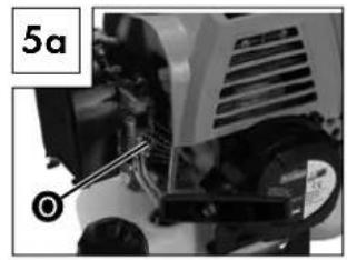
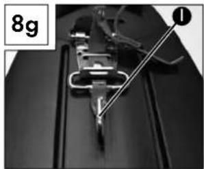
If the device does not come to a stop when the throttle is not engaged and all other causes in accordance with the "Troubleshooting" section have been excluded, it may mean that a readjustment of the idling rate is required. Rotate the idling screw (see fig. 5a) in a clockwise direction until the device idles smoothly. If the idling rate is so high that the cutting tool rotates, this must be reduced by turning the idling screw to the left until the cutting tool no longer rotates.
Lubricating the gears
■ Add gear grease after every 20 hours of operation (approx. 10 g). To do so, open the screw (see fig. 7c).
Spare part orders
Ordering spare parts
The following information must be provided when ordering spare parts:
■ Type of device
■ Item number of the device
■ Device ID number
Current price and information is available at
www.kompernass.com
Storage and transportation
■ Store the device in a safe location.
■ Store the device and accessories in a safe location that is protected against naked flames and sources of heat/sparks, such as gas-powered water heaters, dryers, oil stoves or mobile heaters, etc.
■ Always keep the cutting blade protective hood 14, the line spool 12 and the engine free of mowing residue during storage.
■ Always turn the device off before performing any maintenance work and remove the spark plug connector 30
Storing the device
The device must be prepared for storage if it is to be stored for longer than 30 days. Otherwise the residual fuel in the carburettor will evaporate and leave a rubbery sediment. This may make starting the device more difficult and result in expensive repair work.
1.) Remove the filler cap in order to relieve any pressure in the fuel tank 6. Carefully empty the fuel tank 6.
2.) Start the engine and leave it to run until it stops in order to remove all fuel from the carburettor.
3.) Allow the engine to cool for about 10 minutes.
4.) Remove the spark plug (see "Spark plug maintenance" chapter).
5.) Add 1 teaspoon of 2-stroke oil to the combustion chamber. Pull the starter pull cord 4 several times in order to wet all mechanical parts with oil. Re-insert the spark plug.
NOTE
■ Store the device in a dry place and away from possible ignition sources.
Start-up after storage
1.) Remove the spark plug (see "Spark plug maintenance" chapter).
2.) Pull the starter pull cord ^4 quickly in order to remove any excess oil from the combustion chamber.
3.) Clean the spark plug and observe the correct electrode gap on the spark plug.
4.) Fill the fuel tank ^6 . See "Fuel and oil" section.
Transporting
If you are planning to transport the device, empty the fuel tank ⑥ as explained in the "Storage" section. Remove the guide handle ③ and guide rail ② as described in the "Assembling the guide handle/guide rail" section.
Troubleshooting guide
# = Malfunction
- = Possible cause
* = Troubleshooting
# The device is not starting.
- Incorrect process during start-up.
* Follow the start-up instructions
- Sooted or wet spark plug
* Clean or replace the spark plug.
- Incorrect carburettor setting
Contact customer service
# The device starts but does not run at full power.
- Incorrect choke lever ⑤ setting
* Set choke lever to " | | |".
- Contaminated air filter 29
* Clean air filter
- Incorrect carburettor setting
Contact customer service
# The motor does not run smoothly.
- Incorrect spark plug electrode gap
* Clean the spark plug and adjust the electrode gap or use a new spark plug.
- Incorrect carburettor setting
Contact customer service
Warranty
The warranty provided for this device is 3 years from the date of purchase. This device has been manufactured with care and inspected meticulously prior to delivery. Please retain your receipt as proof of purchase. In the event of a warranty claim, please contact your Customer Service by telephone. This is the only way to guarantee free return of your goods.
The warranty only covers claims for material and manufacturing defects, not for transport damage, wearing parts or for damage to fragile components such as switches or batteries. This device is intended solely for private use and not for commercial purposes.
The warranty is deemed void if this product has been subjected to improper or inappropriate handling, abuse or modifications which were not carried out by one of our authorised service centres. Your statutory rights are not restricted in any way by this warranty.
The warranty period is not prolonged by repairs made under the warranty. This also applies to replaced and repaired parts. Damage and defects present at the time of purchase must be reported immediately after unpacking, or no later than two days after the date of purchase. Repairs made after expiry of the warranty period are chargeable.
Service
WARNING!
■ Only allow your device to be repaired by qualified specialists and only with original spare parts. Thus, you can be certain that the safety of your device is assured.
GB Service Great Britain
Tel.: 0871 5000 720 (£ 0.10/Min.)
E-Mail: kompernass@lidl.co.uk
IAN 97786
IE Service Ireland
Tel.: 1890 930 034
(0,08 EUR/Min., (peak))
(0,06 EUR/Min., (off peak))
E-Mail: kompernass@lidl.ie
IAN 97786
Hotline availability:
KOMPERNASS HANDELS GMBH
BURGSTRASSE 21
44867 BOCHUM
GERMANY
www.kompernass.com
Disposal

packaging is made from environmentally-friendly material and can be disposed off at your local recycling plant.
The device and its accessories are made from various materials, such as metal and plastic.
Your local community or municipal authorities can provide information on how to dispose of the worn-out device.
Environmental protection
■ Carefully empty the petrol and oil tank and dispose of your device at a recycling plant. The plastic and metal parts used can be separated and recycled.
■ Dispose of waste oil and petrol at a waste collection centre, do not dump these into the sewerage or drainage system.
■ Dispose of contaminated maintenance material and working materials at a collection point provided for this purpose.
We, KOMPERNASS HANDELS GMBH, Custodian of Documents:
Mr. Semi Uguzlu, BURGSTR. 21, 44867 BOCHUM, GERMANY, hereby declare that this product complies with the following standards, normative documents and the EC directives:
Machinery Directive (2006/42/EC)
EMC (Electromagnetic Compatibility) (2004/108/EC)
Outdoor Directive (2005/88/EC)
Emissions Directive (2004/26/EC)
Related harmonised standards
EN ISO 11806-1: 2011
EN ISO 14982: 2009
Type / Device designation
Petrol grass trimmer FBS 43 B2
Year of manufacture: 01 - 2014
Serial number: IAN 97786

CE
Semi Uguzlu
- Quality Manager -
Subject to technical changes in the course of further developments.
Sisällysluettelo
Johdanto 12
KOMPERNASS HANDELS GMBH
BURGSTRASSE 21
44867 BOCHUM
GERMANY
www.kompernass.com
Hävittäminen

KOMPERNASS HANDELS GMBH
BURGSTRASSE 21
44867 BOCHUM
GERMANY
www.kompernass.com
Kassering

KOMPERNASS HANDELS GMBH
BURGSTRASSE 21
44867 BOCHUM
GERMANY
www.kompernass.com
Bortskaff else

Contacter le service-client
Contacter le service-client
Contacter le service-client
Garantie
KOMPERNASS HANDELS GMBH
BURGSTRASSE 21
44867 BOCHUM
GERMANY
www.kompernass.com
Mise au rebut

KOMPERNASS HANDELS GMBH
BURGSTRASSE 21
44867 BOCHUM
GERMANY
www.kompernass.com
Afvoeren
KOMPERNASS HANDELS GMBH
BURGSTRASSE 21
44867 BOCHUM
GERMANY
www.kompernass.com
Entsorgung

KOMPERNASS HANDELS GMBH
BURGSTRASSE 21
44867 BOCHUM
DEUTSCHLAND / GERMANY
www.kompernass.com
Last Information Update · Tietojen tila · Informationsstatus
Tilstand af information · Version des informations
Stand van de informatie · Stand der Informationen:
01 / 2014 · Ident.-No.: FBS43B2-122013-4