
DuraVision FDX1203 - Monitor EIZO - Free user manual and instructions
Find the device manual for free DuraVision FDX1203 EIZO in PDF.
| Brand | Eizo |
| Model | DuraVision FDX1203 |
| Category | Monitor |
| Panel type | TN |
| Screen size | 31 cm (12.1 inches) |
| Native resolution | 1024 x 768 pixels |
| Colors | 16.77 million (8-bit) |
| Viewing angles (H/V) | 160° / 140° |
| Contrast ratio | 600:1 |
| Response time | 25 ms (black-white-black) |
| Backlight | LED |
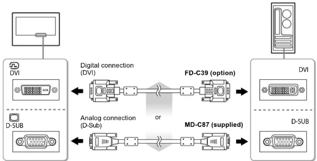
| Video inputs | DVI-D, D-Sub 15-pin |
| Power supply | DC 12 V ±10%, 1.2 A |
| Maximum power consumption | 15.0 W |
| Standby power consumption | ≤ 0.5 W |
| Dimensions (bezel type) | 313 x 234.5 x 52 mm |
| Net weight (bezel type) | 1.8 kg |
| Dimensions (screen type) | 325 x 276 x 51 mm |
| Net weight (screen type) | 2.4 kg |
| Main functions | Brightness adjustment, contrast, color mode, power saving |
| Maintenance and cleaning | Clean with a soft damp cloth, avoid alcohol and solvents |
| Safety | Do not disassemble, avoid shocks and liquids, indoor use only |
| Spare parts and repairability | Contact Eizo after-sales service for any intervention |
Frequently Asked Questions - DuraVision FDX1203 EIZO
User questions about DuraVision FDX1203 EIZO
0 question about this device. Answer the ones you know or ask your own.
Ask a new question about this device
Download the instructions for your Monitor in PDF format for free! Find your manual DuraVision FDX1203 - EIZO and take your electronic device back in hand. On this page are published all the documents necessary for the use of your device. DuraVision FDX1203 by EIZO.
USER MANUAL DuraVision FDX1203 EIZO
Touch Panel Color LCD Monitor
せトアマ ニアル
Important: Please read this Setup Manual and the User's Manual stored (on the CD-ROM) carefully to familiarize yourself with safe and effective usage. Please retain this manual for future reference.
Installationshandbuch
Compatible Resolutions
The monitor supports the following resolutions.
This product is the most popular in the market. It is used to make a lot of things.

| 1 DC12V | |
| 2 | NC |
| 3 Ground | |
※2操作操作末延長用口:S3B-PH-SM4-TB(LF)(SN)(JST)
人力信号接续
Touch Panel Color LCD Monitor
SAFETY SYMBOLS
This manual and this product use the safety symbols below. They denote critical information. Please read them carefully.
| WARNING | Failure to abide by the information in a WARNING may result in serious injury and can be life threatening. |
| CAUTION | Failure to abide by the information in a CAUTION may result in moderate injury and/or property or product damage. |
| △ | Indicates a warning or caution. For example, indicates an "electrical shock" hazard. |
| ⊗ | Indicates a prohibited action. For example, means "Do not disassemble". |
| ● | Indicates a mandatory action. For example, ns "Ground the unit". |
About Setup Manual and User's Manual
| Setup Manual (this manual) | Describes basic information ranging from connection of the monitor to a PC to using the monitor. | |
| User's Manual of this monitor*1 | Describes the application information of the monitor such as screen adjustments, settings, and specifications. | |
| User's Manual of Touch Panel Driver*1 | Describes the installation and use of the touch panel driver. | |
*1 PDF file on the CD-ROM (Installation of Adobe Reader is required.)
No part of this manual may be reproduced, stored in a retrieval system, or transmitted, in any form or by any means, electronic, mechanical, or otherwise, without the prior written permission of EIZO Corporation. EIZO Corporation is under no obligation to hold any submitted material or information confidential unless prior arrangements are made pursuant to EIZO Corporation's receipt of said information. Although every effort has been made to ensure that this manual provides up-to-date information, please note that EIZO monitor specifications are subject to change without notice.
IMPORTANT
-
This product is intended to be used with an industrial device designed to build industrial systems.
-
Transportation systems (Ship, aircraft, train, automobile, etc.)
-
Safety devices (Disaster prevention system, security control system, etc.)
-
Equipment with direct effect on human life (Life support systems, Medical equipment or devices used in the operating room, etc.)
-
Nuclear energy control devices (Nuclear energy control systems, security control systems of nuclear facilities, etc.)
-
Main line devices (Operation control for transportation, control systems specific to aircrafts, etc.)
-
To ensure personal safety and proper maintenance, please read this section.

WARNING
This product is intended to be housed in an enclosure. Do not use the bare monitor separately.
Attempting to use a malfunctioning unit may result in electric shock, or equipment damage.

If the unit begins to emit smoke, smells like something is burning, or makes strange noises, disconnect all power connections immediately and contact your local EIZO representative for advice.
Attempting to use a malfunctioning unit may result in fire, electric shock, or equipment damage.
Do not open the cabinet or modify the unit.
Opening the cabinet or modifying the unit may result in fire, electric shock, or burn.

Refer all servicing to qualified service personnel.
Do not attempt to service this product yourself as opening or removing covers may result in fire, electric shock, or equipment damage.
Keep small objects or liquids away from the unit.
Small objects accidentally falling through the ventilation slots into the cabinet or spillage into the cabinet may result in fire, electric shock, or equipment damage. If an object or liquid falls/ spills into the cabinet, unplug the unit immediately. Have the unit checked by a qualified service engineer before using it again.

Use the unit in an appropriate location.
Not doing so may result in fire, electric shock, or equipment damage.
- Do not place outdoors.
- Do not place in a transportation system (ship, aircraft, train, automobile, etc.) where it may be affected by strong vibration or shock.
- Do not place in a dusty or humid environment.
- Do not place in a location where water is splashed on the screen (bathroom, kitchen, etc.).
- Do not place in a location where the steam comes directly on the screen.
- Do not place near heat generating devices or a humidifier
- Do not place in a location where the product is subject to direct sunlight.
- Do not place in an inflammable gas environment.
- Do not place in environments with corrosive gases (such as sulfur dioxide, hydrogen sulfide, nitrogen dioxide, chlorine, ammonia, and ozone)
- Do not place in environments with dust, components that accelerate corrosion in the atmosphere (such as sodium chloride and sulfur), conductive metals, and so on

Do not touch a damaged LCD panel directly with bare hands.
The liquid crystal that may leak from the panel is poisonous if it enters the eyes or mouth. If any part of the skin or body comes in direct contact with the panel, please wash thoroughly. If some physical symptoms result, please consult your doctor.

Handle with care when carrying the unit.
Disconnect the power cord and cables when moving the unit. Moving the unit with the cord attached is dangerous. It may result in injury.
Do not install the unit in a closed space.
If the inerior becomes hot, it may result in fire, electric shock or damage.

Do not use the power jack and DC power terminal block at the same time.
This may result in fire, electric shock, or damage to the power supply system.

Periodically check the tightening of screws.
If screws are loose, the monitor may detach and cause injury or equipment damage.
Notice for this monitor
| This product may not be covered by warranty for uses other than those described in this manual. |
| The specifications noted in this manual are only applicable when the following are used:· Signal cables specified by us |
| Only use optional products manufactured or specified by us with this product. |
| It takes about 30 minutes for the performance of electrical parts to stabilize. Please wait 30 minutes or more after the monitor power has been turned on, and then adjust the monitor. |
| Monitors should be set to a lower brightness to reduce changes in luminosity caused by long-term use and maintain a stable display. |
| When the screen image is changed after displaying the same image for extended periods of time, an afterimage may appear. Use the screen saver or power save function to avoid displaying the same image for extended periods of time. |
| Periodic cleaning is recommended to keep the monitor looking new and to prolong its operation lifetime (refer to "Cleaning" (page 5)). |
| The LCD panel is manufactured using high-precision technology. Although, missing pixels or lit pixels may appear on the LCD panel, this is not a malfunction. Percentage of effective dots: 99.9994% or higher. |
| The backlight of the LCD panel has a fixed lifetime. When the screen becomes dark or begins to flicker, please contact your local EIZO representative. |
| Do not scratch or press on the panel with any sharp objects, as this may result in damage to the panel. Do not attempt to brush with tissues as this may scratch the panel. |
| When the monitor is cold and brought into a room or the room temperature goes up quickly, dew condensation may occur on the interior and exterior surfaces of the monitor. In that case, do not turn the monitor on. Instead wait until the dew condensation disappears, otherwise it may cause some damage to the monitor. |
| When mounting the monitor in an enclosure, always ground the monitor to avoid the effects of static electricity on the monitor internals and LCD panel. |
| (Cautions for the Use of the Touch Panel)· During touch operationBe careful of the following points. Otherwise, damage may occur to the monitor.- Do not strongly press, scratch, or poke the panel.- Do not touch the panel with hard objects such as ballpoint pens or metals. |
Attention
Chemicals such as alcohol and antiseptic solution may cause gloss variation, tarnishing, and fading of the cabinet or panel, and also quality deterioration of the image.
- Never use any thinner, benzene, wax, and abrasive cleaner, which may damage the cabinet or panel.
- Do not allow liquid to enter the clearance between the panel and the panel frame.
Note
- The optional ScreenCleaner is recommended for cleaning the panel surface.
If necessary, the stains on the panel surface can be removed by moistening part of a soft cloth with water.
To use the monitor comfortably
- An excessively dark or bright screen may affect your eyes. Adjust the brightness of the monitor according to the environmental conditions.
- Staring at the monitor for a long time tires your eyes. Take a 10-minute rest every hour.
Package Contents
Check that all the following items are included in the packaging box. If any items are missing or damaged, contact your local EIZO representative.
Note
- Please keep the packaging box and materials for future movement or transport of the monitor.
Monitor
- Analog signal cable: MD-C87
- USB cable: MD-C93 (for FDX1003T / FDX1203T only)

-
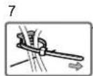
Cable Tie (for FDX1003 / FDX1003T only)
-
EIZO LCD Utility Disk (CD-ROM)
- Setup Manual (this manual)
VESA mounting screws M4 × 10: 4 pcs.
(FDX1003/FDX1003T)
VESA mounting screws M4 × 8:4 pcs.
(FDX1203/FDX1203T)
Metal panel fittings: 4 pcs. (Panel mount type only)
(Precar a screwdriver.)
Attention
- This product does not include a power cord. Please provide separately a power cord which meets the usage requirements.
For more information, please contact your local EIZO representative.
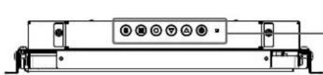
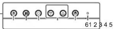
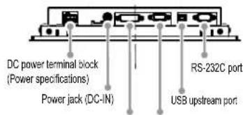
Controls and Functions
Example : FDX1003T (Chassis mount type)
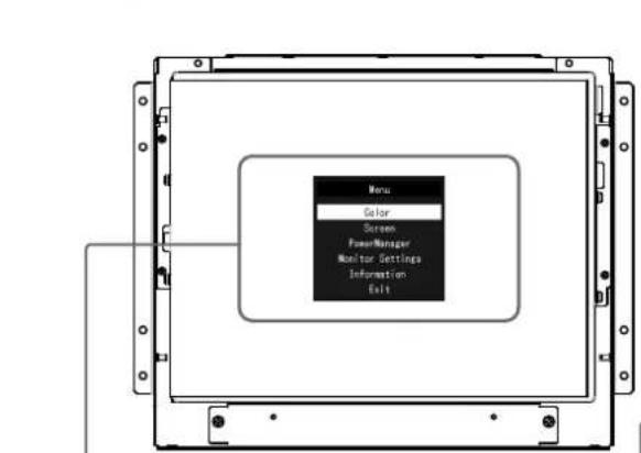
Setting menu
8910
| 1. Button Switches input signals for | display. |
| 2. M button Changes Color Mode. | |
| 3. ● button Displays the Setting me | nu, determines an item on the menu screen, and saves adjusted values. |
| 4. ● button | • Provides the menu selection as well as the adjustment and setting of a function. • Displays the Brightness menu. |
| 5. ● button Turns the power on or off. | |
| 6. Power indicator | Indicates the monitor's operation status. Blue: Operating Orange: Power saving mode OFF: Power off |
| 7. Cable Tie (for FDX1003 / FDX1003T only) | Clinches the cables. |
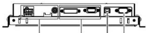
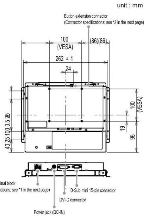
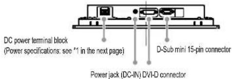
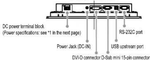
| 8. Power connector | Left: DC power terminal block / Right: Power jack (DC-IN) |
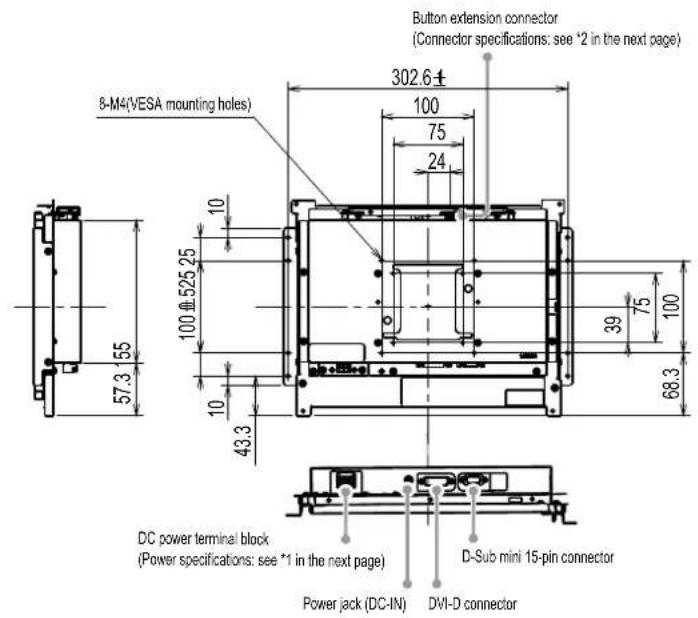
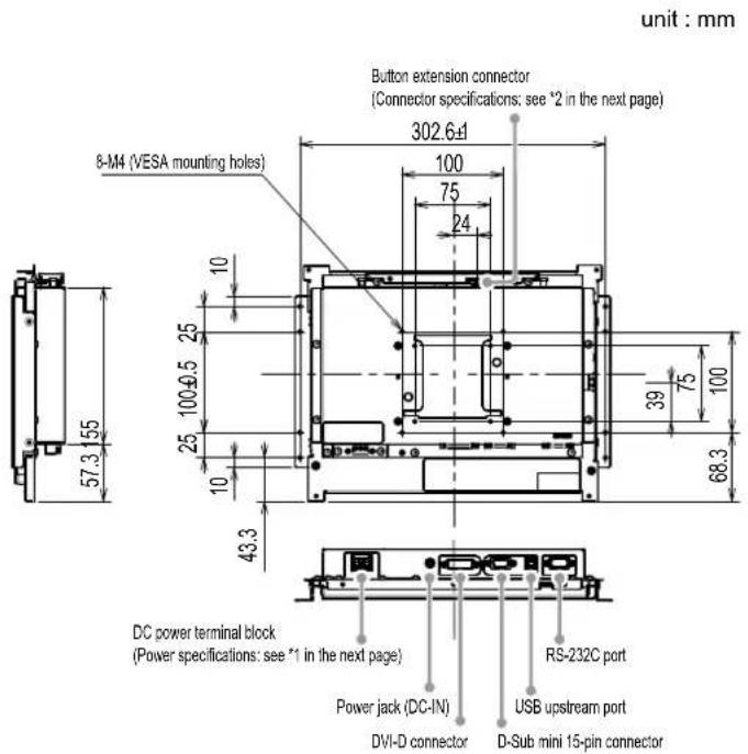
| 9. Input signal connector | Left: DVI-D connector / Right: D-Sub mini 15-pin connector |
| 10. USB upstream port (for FDX1003T / FDX1203T only)*2 | Connects a PC and monitor via a USB cable when this product is used as a touch panel monitor. |
| 11. RS-232C port (for FDX1003T / FDX1203T only)*2 | Connects a PC and monitor via a RS-232C cable when this product is used as a touch panel monitor. |
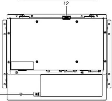
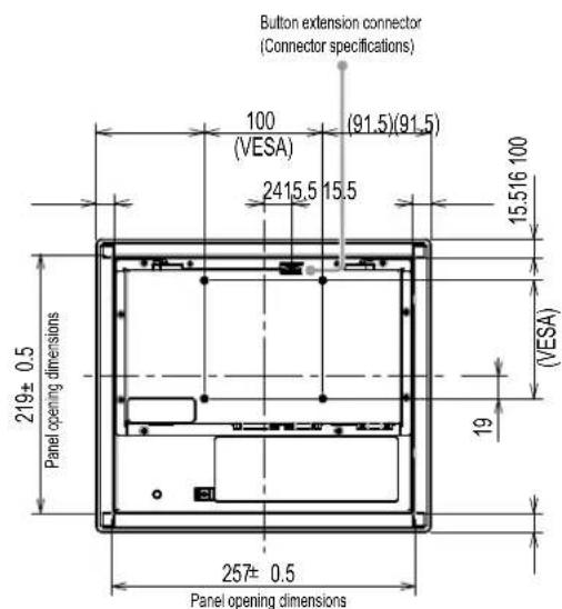
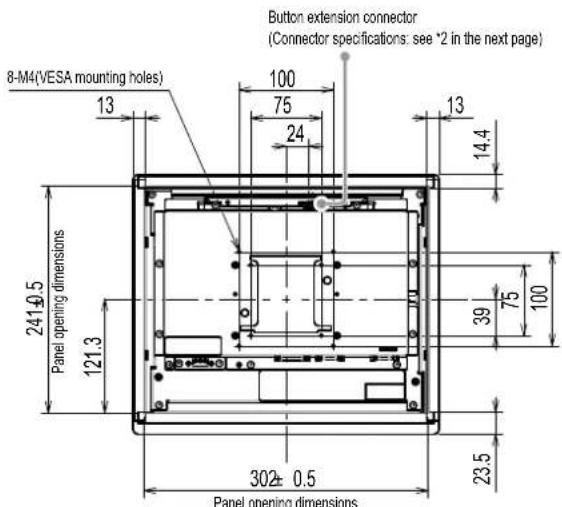
| 12. Button extension connector | This is an extension connector for using the external control buttons. |
1 For instructions for use, refer to the User's Manual on the CD-ROM.
2 These ports cannot be used at the same time. When cables are connected to both ports, the USB port is prioritized.
Assembly
Attention
- Before mounting the monitor into the enclosure, please perform all settings and adjustments of the monitor, and installation of the touch panel driver.
- When attaching an arm or stand, the installable orientations and movement range (tilt angle) are as follows:
| Orientation | ||||
| Movement range (tilt angle) | Up: 90° | Down: 90° | ||
Chassis mount type
Eterior view
FDX1003
FDX1003T
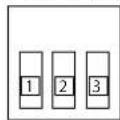
*1 DC power terminal block
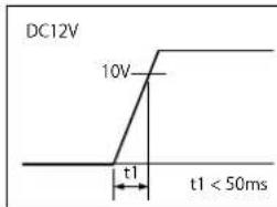
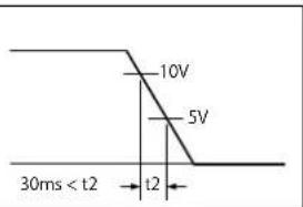
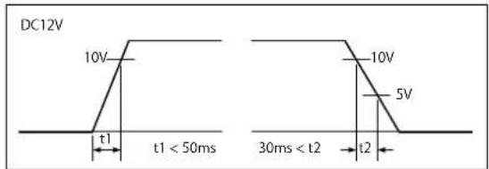
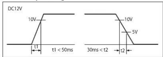
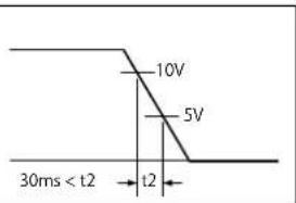
Connector Pin Assignment Power sequencing
Connector Pin Assignment
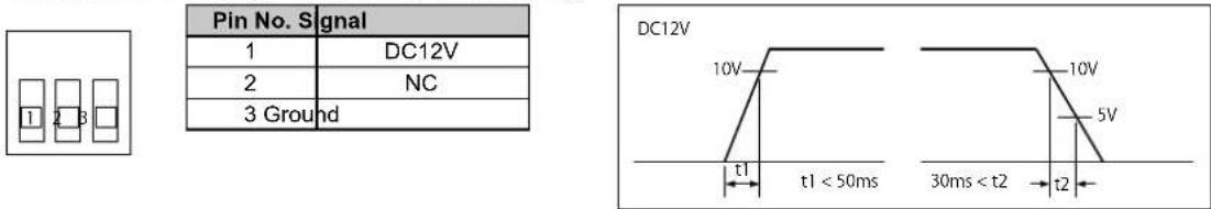
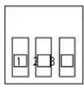
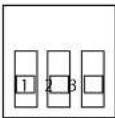
*2 Button extension connector: S3B-PH-SM4-TB(LF)(SN) (JST)
| Pin No. | Sgnal |
| 1 | KEY0 |
| 2 | KEY1 |
| 3 Ground | |
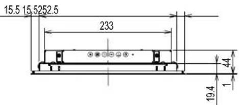
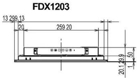
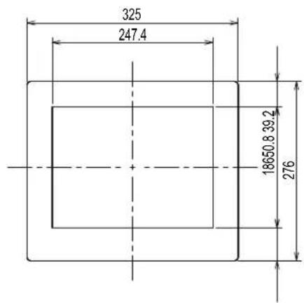
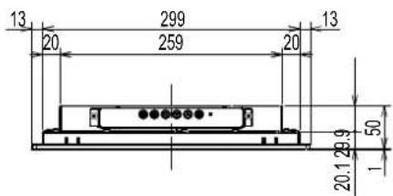
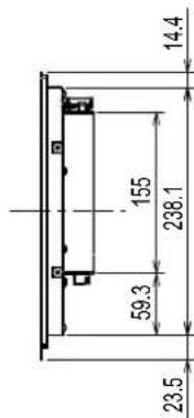
FDX1203
unit: mm
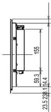
FDX1203T
unit: mm
*1 DC power terminal block
Connector Pin Assignment Power sequencing
| Pin No. Signal | |
| 1 DC12V | |
| 2 | NC |
| 3 Ground | |
*2 Button extension connector: S3B-PH-SM4-TB(LF)(SN) (JST) Connector Pin Assignment
| Pin No. Signal |
| 1 KEY0 |
| 2 KEY1 |
| 3 Ground |
How to assemble
- Fasten the screws through the enclosure mounting holes of the monitor (2 each on the left and right sides) into the enclosure.
Attention
- Please prepare screws that have a diameter of 3mm and are suitable for use with the enclosure. (Screws are not included with the monitor.)
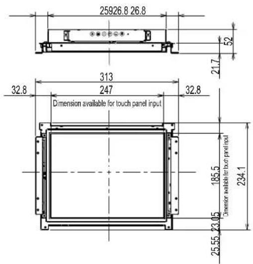
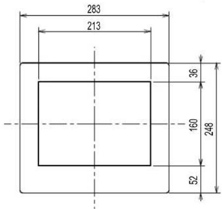
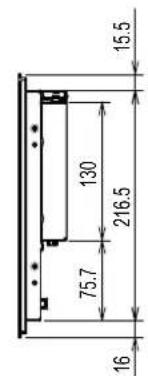
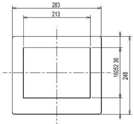
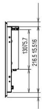
Panel mount type
Eterior view
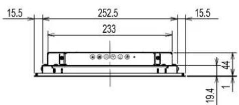
FDX1003
unit: mm

FDX1003T
unit: mm
*1 DC power terminal block
Connector Pin Assignment
Power sequencing
| Pin No. | Signal |
| 1 | DC12V |
| 2 | NC |
| 3 | Ground |
*2 Button extension connector: S3B-PH-SM4-TB(LF)(SN) (JST)
Connector Pin Assignment
| Pin No. | Signal |
| 1 | KEY0 |
| 2 | KEY1 |
| 3 | Ground |
unit: mm
FDX1203T
unit: mm
*1 DC power terminal block
Connector Pin Assignment Power sequencing
| Pin No. | Sgnal |
| 1 | DC12V |
| 2 | NC |
| 3 | Ground |

*2 Button extension connector: S3B-PH-SM4-TB(LF)(SN) (JST)
Connector Pin Assignment
| Pin No. Signal |
| 1 KEY0 |
| 2 KEY1 |
| 3 Ground |
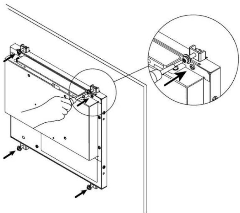
How to assemble
Attention
-
Since the panel mounted on the monitor is tightened with a metal panel fitting screw, please make the selection considering the following points.
-
Flat
-A thickness of 5mm -
A structure having the strength to support fixing with the screw.
-
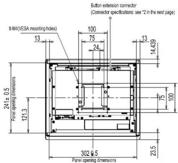
Insert the monitor into the mount opening of the panel from the front.
The dimensions of a fitting opening are the "Panel opening dimensions" shown in the exterior view.
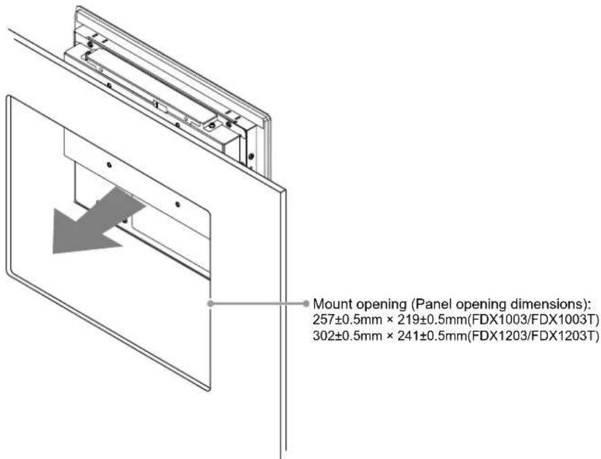
- Fit the included metal panel fittings onto the monitor (4 locations).
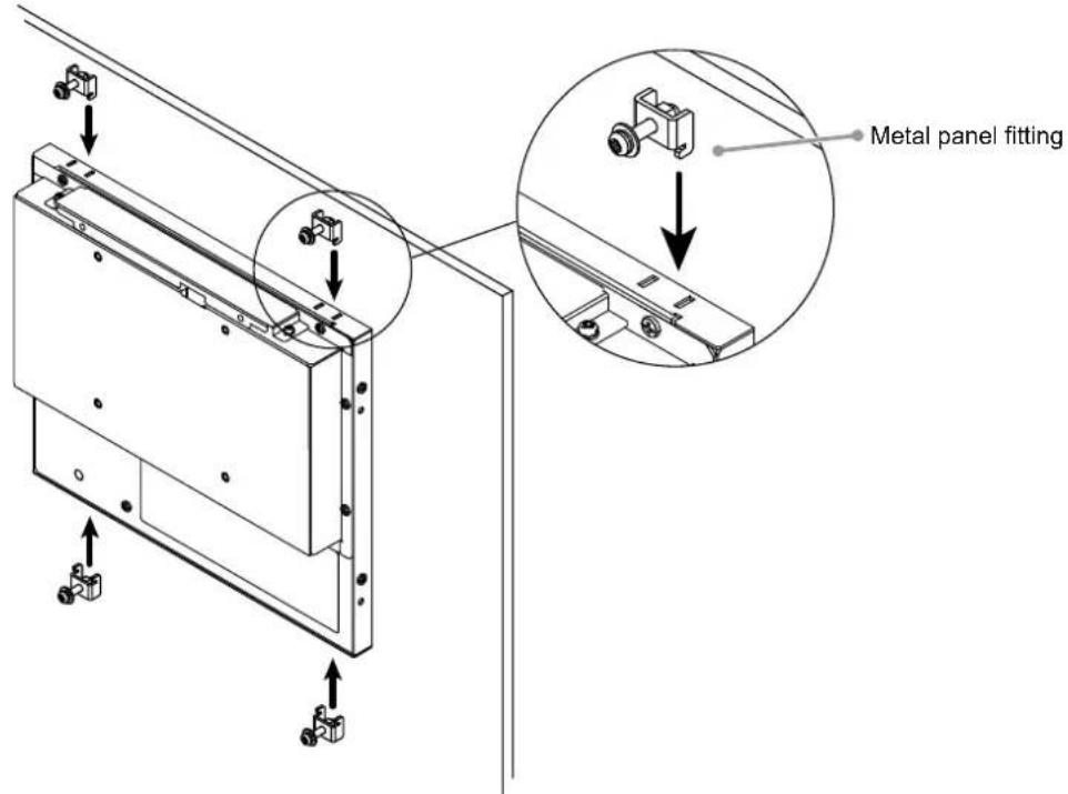
- Tighten the screws of the metal panel fittings with a prescribed torque of 0.6 - 0.7Ndot m
Attention
- Check that the monitor and the PC are powered off.
- When replacing the current monitor with this monitor, be sure to change the PC settings for resolution and vertical scan frequency to those that are available for this monitor. Refer to the compatible resolution table before connecting the PC.
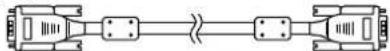
1. Connect the signal cables to the input signal connectors and PC.
Check the shape of the connectors, and connect the cables.
After connecting the signal cable, tighten the screws of the connectors to secure the coupling.
2. Connect the monitor to a power supply.
There are two options for connecting the monitor to a power supply. Make the connection according to the installation environment and conditions of use.
- Using the DC power terminal block
Using the DC power jack (DC-IN)
Displaying the Screen
1. Press to turn on the monitor.
The monitor's power indicator lights up blue.
2. Turn on the PC.
The screen image appears.
If an image does not appear, refer to "No picture" (page 17) for additional advice.
If using the FDX1003T/FDX1203T proceed with installation and calibration of the touch panel driver.
Attention
- Turn off the monitor and PC after using them.
- For the maximum power saving, it is recommended that the Power button be turned off. Unplugging the power cord completely shuts off power supply to the monitor.
Installing the Touch Panel Driver (FDX1003T / FDX1203T)
Attention
- The user account to be used for installing the touch panel driver must have the "Administrators" privilege.
-
When reinstalling the touch panel driver to update the driver, etc., restart the PC after uninstalling the driver and then install it.
-
Uninstall the other touch panel driver, if it is installed.
- Install the touch panel driver according to the instructions included in the CD-ROM.
For how to install the touch panel driver, see the Touch Panel Driver User's Manual (on the CD-ROM).
- Use the USB cable or RS-232C cable to connect the monitor and the PC.
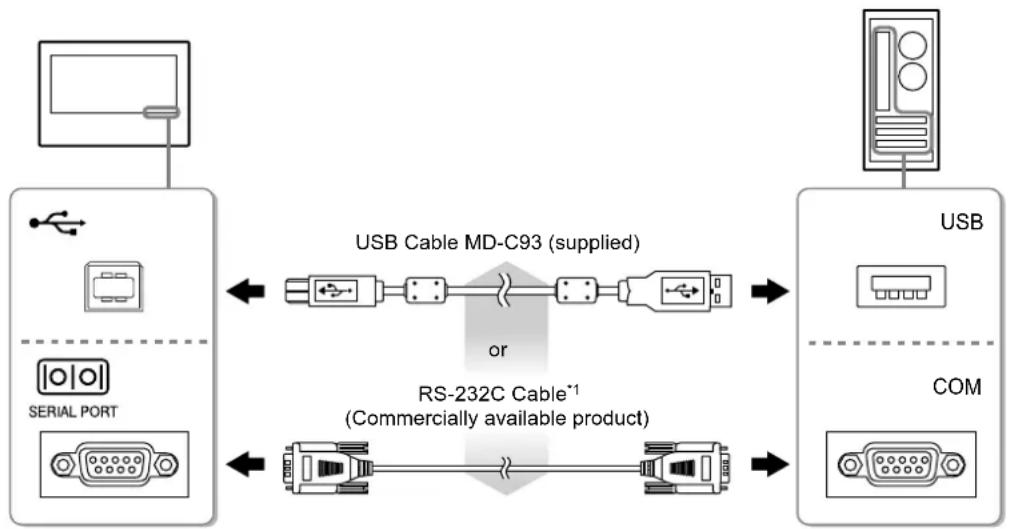
*1 crossover type
- Restart the PC.
Attention
- When using the RS-232C cable with Windows 7 / Windows Vista / Windows XP, set up the device using the following procedure after the restart. For details, refer to the Touch Panel Driver User's Manual (on the CD-ROM).
- Click "Start" - "All Program" - "DMC" - "DMC Touch Panel Configuration" to display "Properties" window.
- Click "Add a serial device", and register a new serial device.
- Click "Device", and specify the COM port number used for the "COM port".
- Click "Apply".
- Click "Close".
Calibrating the Monitor (FDX1003T / FDX1203T)
Calibrate the monitor according to the Touch Panel Driver User's Manual (on the CD-ROM).
Note
- If its installation location has changed, please perform calibration.
Troubleshooting
No picture
If a problem still remains after applying the suggested remedies, contact your local EIZO representative.
| Problem Possible cause and remedy | |
| 1. No picture • Power indicator does not light. | • Check whether the power cord is connected properly. • Press ①. • If the problem persists, turn off the power, and then turn it on again a few minutes later. |
| • Power indicator is lighting blue. • Power indicator is lighting orange. | • Increase "Brightness" and/or "Gain" in the Setting menu. • Switch the input signal with ⑧. • Move the mouse or press any key on the keyboard. • Check whether the PC is turned on. • Depending on the PC and graphics board, the input signal is not detected and the monitor does not recover from the power saving mode. If the screen is not displayed even after moving the mouse or pressing any key on the keyboard, turn the monitor off and on using its power button. When the screen is displayed, execute the following procedure. The problem may be improved. 1. Press ⑨ to turn off the monitor. 2. Hold down ⑩ while pressing ⑪ turn on the monitor. “x” is displayed on the menu title of “Information” of the Setting menu. 3. Reboot the PC. To return to the previous setting, perform steps 1 to 3 again. |
| 2. The message below appears. | This message appears when the signal is not input correctly even when the monitor functions properly. |
| • The message shows that the input signal is out of the specified frequency range. Example: DVI Signal Error | • Check whether the PC is configured to meet the resolution and vertical scan frequency requirements of the monitor (see "Compatible Resolutions"). • Reboot the PC. • Select an appropriate setting using the graphics board's utility. Refer to the User's Manual of the graphics board for details. |
Note
- If there is a problem with the image displayed or with the touch panel, refer to the Monitor User's Manual (on the CD-ROM).
Specifications
| FDX1003 FDX1003T | LCD Panel | ||
| Type TN | |||
| Backlight LED | |||
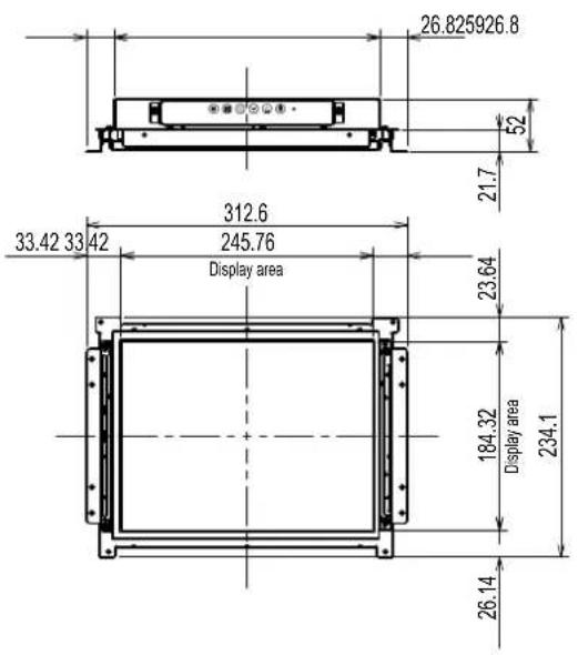
| Size 26 cm (10.4 inch) (26.3 cm diagonal) | |||
| Native Resolution 1024 dots × 768 lines | |||
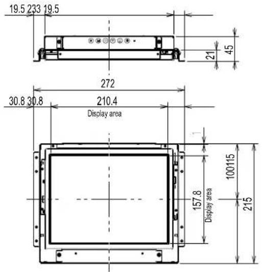
| Display Size (H x V) 210.4 mm × 157.8 mm | |||
| Pixel Pitch 0.2055 mm | |||
| Display Colors 8 bit colors : 16.77 million colors | |||
| Viewing Angles (H / V, typical) | 160° / 130° | ||
| Contrast ratio (typical) 700 : 1 | |||
| Response Time (typical) 16 ms (Black - white - black) | |||
| Power | |||
| Input DC 12 V ± 10%, 0.7 A | |||
| Maximum Power Consumption | 9.0 W or less | ||
| Standby Mode | 0.5 W or less | ||
| Physical Specifications | |||
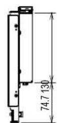
| Dimensions (Width) × (Height) × Depth) | Chassis mount type | 272 mm × 215 mm × 45 mm | |
| Panel mount type | 283 mm × 248 mm × 45 mm | ||
| Net Weight | Chassis mount type | FDX1003 : Approx. 1.7 kg | |
| FDX1003T : Approx. 1.9 kg | |||
| Panel mount type | FDX1003 : Approx. 2.2 kg | ||
| FDX1003T : Approx. 2.3 kg | |||
| FDX1203 FDX1203T | LCD Panel | ||
| Type TN | |||
| Backlight LED | |||
| Size 31 cm (12.1 inch) (30.7 cm diagonal) | |||
| Native Resolution 1024 dots × 768 lines | |||
| Display Size (H x V) 245.7 mm × 184.3 mm | |||
| Pixel Pitch 0.240 mm | |||
| Display Colors 8 bit colors : 16 | 77 million colors | ||
| Viewing Angles (H / V, typical) | 160° / 140° | ||
| Contrast ratio (typical) 600 : 1 | |||
| Response Time (typical) 25ms (Black - white - black) | |||
| Power | |||
| Input DC 12 V ± 10%, 1.2 A | |||
| Maximum Power Consumption | 15.0 W or less | ||
| Standby Mode | 0.5 W or less | ||
| Physical Specifications | |||
| Dimensions (Width) × (Height) × Depth) | Chassis mount type | 313 mm × 234.5 mm × 52 mm | |
| Panel mount type | 325 mm × 276 mm × 51 mm | ||
| Net Weight | Chassis mount type | FDX1203 : Approx. 1.8 kg FDX1203T : Approx. 2.1 kg | |
| Panel mount type | FDX1203 : Approx. 2.4 kg FDX1203T : Approx. 2.6 kg | ||
| FDX1003T FDX1203T | Touch Panel | ||
| Method | Analog resistive technology | ||
| Communication method | USB, RS-232C (* Cannot be used at the same time.) | ||
| Surface treatment | Anti-reflection | ||
| Surface hardness | 2H | ||
| OS *1 | Microsoft Windows 11 (64 bit) Microsoft Windows 10 (32 bit / 64 bit) Microsoft Windows 8.1 (32 bit / 64 bit) Microsoft Windows 7 Service Pack 1 (32 bit / 64 bit) Microsoft Windows Vista Service Pack 2 (32 bit) Microsoft Windows XP Service Pack 3 (32 bit) (Not compatible with Mac OS) | ||
| FDX1003 FDX1203 FDX1003T FDX1203T | Video Signals | ||
| Input Terminals DVI-D connector × 1, D-Sub mini 15-pin × 1 | |||
| Digital Scanning Frequency (H / V) | 31 kHz - 49 kHz / 59 Hz - 61 Hz (720 × 400 : 69 Hz - 71 Hz) | ||
| Analog scan frequency Frequency (H / V) | 24 kHz - 61 kHz / 55 Hz - 76 Hz | ||
| Dot Clock Digital 65 MHz | Analog 80 MHz | ||
| Synchronous signal Separate, TTL, positive/negative | |||
| Communication | |||
| Input Terminals RS-232C : D-Sub 9-pin (male) | |||
| USB | |||
| Port Upstream port × 1 | |||
| Standard USB Specification Rev.2.0 | |||
| Operating Environmental Requirements | |||
| Temperature 0°C to 50°C (32°F to 122°F) | |||
| Humidity 20% to 90% R.H.(no condensation) | |||
| Air pressure 540 hPa to 1060 hPa | |||
| Transportation / Storage Environmental Requirements | |||
| Temperature -20°C to 60°C (-4°F to 140°F) | |||
| Humidity 10% to 90% R.H (no condensation) | |||
| Air pressure 200 hPa to 1060 hPa | |||
*1 EIZO support will end when OS vendor support ends.
- Main default settings
| Color Mode | User1 |
| Smoothing | 3 |
| Power Save | On |
| Eco Timer | Off |
| Language | English |
| Touch Panel | Auto |
DuraVision® FDX1003/FDX1203
LCD-Farbmonitor
DuraVision® FDX1003T/FDX1203T
- Installationshandbuch
(das vorliegende Handbuch)
This warranty is valid only in Japan.
Belgrader Straße 2, 41069 Monchengladbach, Germany
艺卓显像技术(苏州)有限公司

- Touch Panel Color LCD Monitor
- せトアマ ニアル
- Installationshandbuch
- SAFETY SYMBOLS
- About Setup Manual and User's Manual
- IMPORTANT
- WARNING
- Notice for this monitor
- Attention
- Note
- To use the monitor comfortably
- Package Contents
- Controls and Functions
- Assembly
- Chassis mount type
- Eterior view
- FDX1003
- Connector Pin Assignment Power sequencing
- How to assemble
- Panel mount type
- FDX1003T
- Connector Pin Assignment
- Connect the signal cables to the input signal connectors and PC.
- Connect the monitor to a power supply.
- Displaying the Screen
- Press to turn on the monitor.
- Turn on the PC.
- Installing the Touch Panel Driver (FDX1003T / FDX1203T)
- Calibrating the Monitor (FDX1003T / FDX1203T)
- Troubleshooting
- No picture
- Specifications
- - Main default settings
- DuraVision® FDX1003/FDX1203
- DuraVision® FDX1003T/FDX1203T
- 艺卓显像技术(苏州)有限公司
Brand : EIZO
Model : DuraVision FDX1203
Category : Monitor