
UG 500575 FFK - Washing machine MIELE - Free user manual and instructions
Find the device manual for free UG 500575 FFK MIELE in PDF.

| Product type | Washing machine |
| Brand | Miele |
| Model | UG 500575 FFK |
| Dimensions (H x W x D) | 85 x 60 x 60 cm |
| Weight | Approx. 80 kg |
| Power supply | 230 V / 50 Hz |
| Power consumption | Approx. 2000 W |
| Washing capacity | 7 kg |
| Loading type | Front |
| Washing programs | Cotton, synthetics, delicates, etc. |
| Maximum spin speed | 1400 rpm |
| Special functions | Integrated FFK lint collection tray |
| Safety | Child lock, automatic shutdown |
| Maintenance and cleaning | Clean the filter after each wash |
| Spare parts available | Filter, drawer, lint collection tray |
| Water connection | Cold and hot water |
| Gas connection | Possible (depending on model) |
| Pedestal installation | Compatible with pedestal UO 5005-08 or UG 5006-75 |
| Warranty | 2 years |
Frequently Asked Questions - UG 500575 FFK MIELE
User questions about UG 500575 FFK MIELE
0 question about this device. Answer the ones you know or ask your own.
Ask a new question about this device
Download the instructions for your Washing machine in PDF format for free! Find your manual UG 500575 FFK - MIELE and take your electronic device back in hand. On this page are published all the documents necessary for the use of your device. UG 500575 FFK by MIELE.
USER MANUAL UG 500575 FFK MIELE
3
4
natural_image
Technical line drawing of a mechanical support structure with mounting feet and a cylindrical component (no text or symbols)5
107312111 Thesefittinginstructions
Note
Service and repair work should only be carried out by a suitably qualified electrician (with specialist training, knowledge and experience, and recent related work experience) in accordance with all appropriatelocal and national safety regulations.
Servicing, modification, testing and maintenance of electrical appliances should only be carried out in accordance with all appropriate legal requirements, accidentpreventionregulationsandvalidstandards.
All regulations of the appropriate utility supply companies and standards relating to safety (not limited to electrical safety) are to be complied with.
Note
Service and repair work on gas machines should only be carried out by suitably qualified persons in accordance with all appropriate local and national safety regulations. Ensure all special regulations applying to gas installations are also complied with.
Beforeanyserviceworkiscommenced, themachinemustbedisconnectedfromthegasmains.
Danger!
Evenwiththemachineswitchedoff,mainsvoltagemaybeappliedtosomecomponents.
Before any service work is commenced, the machine must be disconnected from the mains. Suitable measurements must be made to ensure that this is the case.
Ageneralvisualcheckshouldalwaysbecarriedout.
Incorrectconversionorserviceworkcouldleadtoariskoffireorgasexplosion.
Danger!
Riskofinjury
• Risk of electric shock. Before any service work is commenced, the machine must be disconnected from the mains.
- Fitting can only be carried out with the washing machine or tumble dryer not installed. For deinstallation, see the appropriate operating instructions.
- Riskofcrushing.Wearslip-proofworkingglovesandsafetyshoes.
• Risk of crushing. Ensure that parts of the body, especially the hands and feet are not positioned under or between machines.
• Risk of accident. Ensure that children or pets cannot access the work area while fitting work is being carried out.
- Risk of injury, particularly to the back. When carrying out this installation work, it is necessary to lay the washing machine on its side. For this the relation of the weight of the machine to the physical strength of the technician must be taken into account. If this instruction is not followed, serious injury, especially back injury, could be the result. For machine weight details, see the appropriate operating instructions.
- Riskofinjury. Donotstand, orallowanyonetostand, onthedrawer.
Riskoftipping.Riskofinjuryduetoincorrectassembly.
- Duetotheriskoftipping, themachinemustalwaysbeboltedtotheplinth.
With a single machine installation, secure the plinth to the floor with the floor fastening kit Mat. no. 01497252. - Allfourplinthfeetmustbeboltedtothefloor.
•Theplinthisnotsuitableforusewithawasher-dryerstack.
Note
Toolsrequired:
•Spiritlevelforplinthlevelling
- Openspanner,8mm,forM5nut
•Torx20screwdriver
• Ifholesneedtobedrilledintheplinth:6mmdrillbitforsteel,7mmdrillbitforsteel
Note
Thekit, Mat.no.07312050, containsthefollowing:
- 1 filterboxguide
- 1drainplate
- 1 connectionbox
- 1 filterbox(drawer)
•1lock -
1 filter(surfacefilter)
-
1 accessory pack for fluff filter box fastening with case, 6 cheese-head bolts M5 x 12, 6 stainless-steel nuts M5, 6 stainless steel washersB5.3,2pipebends70x87PP(90° bendfordrainpath),1key.
- 1 informationaccessorypackwiththesefittinginstructionsandcommissioningcard.
Listofillustrations:
-Fig.1,plinthfrontviewwithdimensionsfortwo6mmdia.holes
-Fig.2,plinthrearviewwithdimensionsforfour7mmdiaholes
– Fig. 3, assembly of connection box (Pos. 1), guide rails (Pos. 2), drain plate (Pos. 3) with stopper bracket (Pos. 4) and plinth
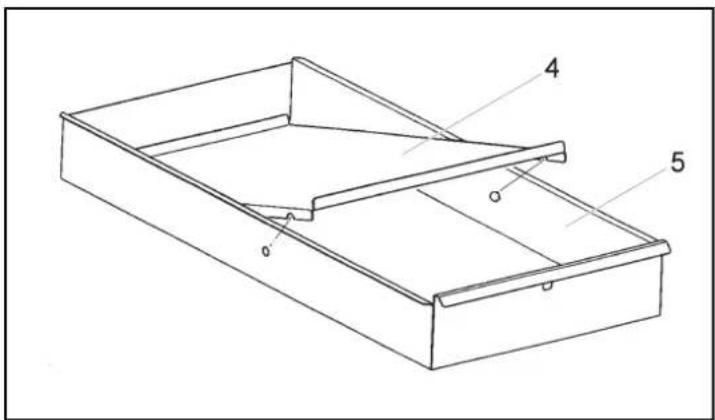
-Fig.4, assembly of surface filter (Pos.4) and drawer (Pos.5)
– Fig. 5, plinth with fitted fluff filter box showing position of the two 90° bends from machine drain into connection box
—Fig.6, detailofinstallationplanforplinthwithflufffilterboxforconnectiontodrain
Fig.6, legendfordetailofinstallationplan
| AbbreviationExplanation | |
| AVModelwithdrainvalve | |
| AWDrainconnection | |
| DN70Pipe(drainpipe)diameter(diameternominal)70mm | |
| ELElectricalconnection | |
| FFKFlufffilterbox | |
| KWColdwaterconnection(softwater) | |
| UMMieleplinth | |
| WWHotwaterconnection(softwater) |
Table1:Legendfordetailofinstallationplan
-Ifapplicable,closethegasmainsstopcock.
- Disconnect the machine from the electrical mains and, if applicable, from the gas mains. Measures must be taken to ensure utility supplies cannot be switched on again in error.
A new plinth has two 6 mm dia. holes in the front on the cover plate as shown, Fig. 1, and the rear has two 7 mm dia. holes in the cover plateanda7mmdiaholeineachrearfoot, seeFig.2.
- With an unprepared or older plinth, two holes each are to be made in the front, see Fig. 1, and the rear, see Fig. 2, of the cover plate and, in addition, oneholeistobedrilledineachrearfoot.
-Placetheconnectionbox, Fig.3, Pos.1, inpositionattherearoftheplinth. - Fit the drain plate, Fig. 3, Pos. 3, with guide rails, Fig. 3, Pos. 2, with 4 M5 cheese-head bolts (torque 3.8Nm ).
– Slide the guide rails, Fig. 3, Pos. 2, with the fitted drain plate at the rear onto the connection box threaded bolts, ensuring that the stopperbracketonthedrainplatefacesthefront,seeFig.3,Pos.4.
- Secure the guide rails in the front of the plinth on the cover plate with 2 M5 cheese-head bolts, washers, and M5 nuts (torque3.8Nm)ineachcase.
- Fit the surface filter, Fig. 4, Pos. 4, in the drawer, Fig. 4, Pos. 5, and press it into its retainers.
- Fit the drawer in the guide rails and push it in as far as the stopper bracket (pull-out stop). Then lift it slightly and push it in fully.
- Fit the two 90^ pipe bends together and lay them from the machine drain outlet to the connection box, Fig. 5.
Danger!
Risk of tipping and falling! It is absolutely essential to bolt the machine to the plinth, and to bolt the plinth to the floor! See the plinth fitting instructions for UO5005-08 or UG5005-75 (supplied with the plinth).
Note
Fordetailsofthedrainconnectiontothefloororwall,seetheinstallationplanforPW5064ELMOPP.
Danger!
Riskofscaldingduetodrainageofhotsuds.
Risk of chemical burns to the skin and eyes due to drainage of aggressive suds. The machine must only be operated with the drawer fittedandfullyclosed.Onlyopenthedraweraftertheprogrammehasfinishedcompletely.
Danger!
Risk of injury due to falling drawer. The stop bracket prevents the drawer being fully pulled out after it has been moved approx. 100 mm. The operator can override this stop by lifting the drawer slightly and pulling. The drawer can then be removed completely.
Note
When fitting the drawer, take care with the stop. The operator can override this stop by lifting the drawer slightly and pushing. The drawer can then be pushed incompletely.
Note
Check the surface filter after every wash cycle. If necessary clean the filter and then refit it in its retainers in the drawer.
-Carryoutappropriatesafetychecks.
-Reconnectthemachinetotheelectricalmainsand,ifapplicable,tothegasmains.
- Carry out a functional test either with a service programme or a wash programme. Carry out a check for leaks between the machine drainexitandthedrainconnectioninthefloororwall.
en
Service and repair work should only be carried out by a suitably qualified electrician (with specialist training, knowledge and experience, and recent related work experience) in accordance with all appropriatelocal and national safety regulations.
Servicing, modification, testing and maintenance of electrical appliances should only be carried out in accordance with all appropriate legal requirements, accidentpreventionregulationsandvalidstandards.
All regulations of the appropriate utility supply companies and standards relating to safety (not limited to electrical safety) are to be complied with.
Note
Service and repair work on gas machines should only be carried out by suitably qualified persons in accordance with all appropriate local and national safety regulations. Ensure that all special regulations applying to gas installations are also complied with.
Beforestartinganyservicework, themachinemustbedisconnectedfromthegassupply.
Danger!
Evenwiththemachineswitchedoff, voltagemaybeappliedtosomecomponents.
Before starting any service work, the machine must be disconnected from the power supply. Suitable measurements must be made to ensure that this is the case.
Ageneralvisualcheckshouldalwaysbecarriedout.
Incorrectconversionorserviceworkcouldleadtoariskoffireorgasexplosion.
Danger!
Riskofinjury:
• Risk of electric shock. Before starting any service work, the machine must be disconnected from the power supply.
• Installation can only be carried out with the washing machine or tumble dryer not installed. For deinstallation, see the appropriate operating instructions.
- Riskofcrushing.Wearslip-proofworkingglovesandsafetyshoes.
- Risk of crushing. Ensure that parts of the body, especially the hands and feet, are not positioned under or between machines.
• Risk of accident. Ensure that children or pets cannot access the work area while installation work is being carried out.
- Risk of injury, particularly to the back. When carrying out this installation work, it is necessary to lay the washing machine on its side. For this the relation of the weight of the machine to the physical strength of the technician must be taken into account. If this instruction is not followed, serious injury, especially back injury, could be the result. For machine weight details, see the appropriate operating instructions.
- Riskofinjury. Donotstand, orallowanyonetostand, onthedrawer.
Riskoftipping.Riskofinjuryduetoincorrectassembly.
- Duetotheriskoftipping, themachinemustalwaysbeboltedtothestand.
With a single machine installation, secure the stand to the floor with the floor fastening kit, mat. no. 01497252.
- Allfourstandfeetmustbeboltedtothefloor.
- Thestandisnotsuitableforusewithawasher-dryerstack.
Note
Toolsrequired:
•Spirit/bubblelevelforstandlevelling
•Openwrench,8mm,forM5nut
•Torx20screwdriver
•Ifholesneedtobedrilledinthestand:6mmdrillbitforsteel,7mmdrillbitforsteel
Note
Thekit,mat.no.07312050,containsthefollowing:
- 1 filterboxguide
- 1drainplate
- 1 connectionbox
- 1 filterbox(drawer)
•1lock - 1 filter(surfacefilter)
- 1 accessory pack for lint filter box fastening with case, 6 M5 x 12 cheese-head bolts, 6 M5 stainless-steel nuts, 6 B5.3 stainless-steelwashers,2pipebends70x87PP(90°bendfordrainpath),1key.
- 1 informationaccessorypackwiththeseinstructionsandstartupcard.
Listofillustrations:
—Fig.1, standfrontviewwithdimensionsfortwo6mmdia.holes
-Fig.2, standrearview with dimensions for four 7 mmdiaholes
– Fig. 3, assembly of connection box (Pos. 1), guide rails (Pos. 2), drain plate (Pos. 3) with stopper bracket (Pos. 4) and stand
-Fig.4, assembly of surface filter (Pos.4) and drawer (Pos.5)
Fig. 5, stand with installed lint filter box showing position of the two 90^ bends from machine drain into connection box
—Fig.6, detailofinstallationplanforstandwithlintfilterboxforconnectiontodrain
Fig.6, legendfordetailofinstallationplan
| AbbreviationExplanation | |
| AVModelwithdrainvalve | |
| AWDrainconnection | |
| DN70Pipe(drainpipe)diameter,70mm(nominal) | |
| ELElectricalconnection | |
| FFKLintfilterbox | |
| KWCold-waterconnection(softwater) | |
| UMMielestand | |
| WWHot-waterconnection(softwater) |
Table1:LegendforDetailofInstallationPlan
-Ifapplicable,closethegasshutoffvalve.
- Disconnect the machine from the electrical supply and, if applicable, from the gas supply. Measures must be taken to ensure that utilitysuppliescannotbeswitchedonagaininerror.
A new stand has two 6mm holes in the front on the cover plate as shown in Fig. 1, and the rear has two 7mm holes in the cover plate and a 7mmholeineachrearfoot; seeFig.2.
- With an unprepared or older stand, two holes each are to be made in the front (see Fig. 1) and the rear (see Fig. 2) of the cover plate and, in addition, oneholeistobedrilledineachrearfoot.
-Placetheconnectionbox(Fig.3,Pos.1)totherearofthestand.
— Install the drain plate (Fig. 3, Pos. 3) with guide rails (Fig. 3, Pos. 2) with 4 M5 cheese-head bolts (torque 3.8 Nm). - Slide the guide rails (Fig. 3, Pos. 2) with the installed drain plate at the rear on the connection box threaded bolts. The stopper bracketonthedrainplatefacesthefront;seeFig.3,Pos.4.
FastentheguiderailswithdrainplatetothecomconnectionboxusingthewashersandM5nuts(torque3.8Nm).
- Fasten the guide rails to the front of the stand on the cover plate with 2 M5 cheese-head bolts, washers, and M5 nuts (torque3.8Nm)ineachcase.
— Install the surface filter (Fig. 4, Pos. 4) in the drawer (Fig. 4, Pos. 5) and press it into its retainers.
— Install the drawer in the guide rails and push it in as far as the stopper bracket (pull-out stop). Then lift it slightly and push it in fully.
— Install the two 90° pipe bends together and lay them from the machine drain outlet to the connection box. See Fig. 5.
Danger!
Risk of tipping and falling! It is absolutely essential to bolt the machine to the stand, and to bolt the stand to the floor! See the stand installation instructions for UO5005-08 or UG5005-75 (supplied with the stand).
Note
Fordetailsofthedrainconnectiontothefloororwall,seetheinstallationplanforPW5064ELMOPP.
Danger!
Riskofscaldingduetodrainageofhotsuds.
Risk of chemical burns to the skin and eyes due to drainage of aggressive suds. The machine must only be operated with the drawer installedandfullyclosed.Onlyopenthedraweraftertheprogrammehasfinishedcompletely.
Danger!
Risk of injury due to falling drawer. The stop bracket prevents the drawer being fully pulled out after it has been moved approximately 100 mm. The operator can override this stop by lifting the drawer slightly and pulling. The drawer can then be removed completely.
Note
When installing the drawer, take care with the stop. The operator can override this stop by lifting the drawer slightly and pushing. The drawercanthenbepushedincompletely.
Note
Check the surface filter after every wash cycle. If necessary clean the filter and then re-install it in its retainers in the drawer.
-Carryoutappropriatesafetychecks.
- Reconnectthemachinetotheelectricalsupply and, if applicable, tothegassupply.
- Carry out a functional test either with a service program or a wash program. Carry out a check for leaks between the machine drain exitandthedrainconnectioninthefloororwall.