DHE 21 SLi - Electric water heater STIEBEL ELTRON - Free user manual and instructions
Find the device manual for free DHE 21 SLi STIEBEL ELTRON in PDF.
Frequently Asked Questions - DHE 21 SLi STIEBEL ELTRON
User questions about DHE 21 SLi STIEBEL ELTRON
0 question about this device. Answer the ones you know or ask your own.
Ask a new question about this device
Download the instructions for your Electric water heater in PDF format for free! Find your manual DHE 21 SLi - STIEBEL ELTRON and take your electronic device back in hand. On this page are published all the documents necessary for the use of your device. DHE 21 SLi by STIEBEL ELTRON.
USER MANUAL DHE 21 SLi STIEBEL ELTRON
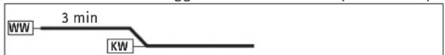
WW = Warmwasser, KW = Kaltwasser
$$ E u r = \epsilon $$
$$ \operatorname {c u r} = \text {c u r e n c y (b e l i e b i g e a n d e W a h r u n g)} $$
- General information 22
1.1 Safety instructions 22
1.2 Other symbols in this documentation 23
1.3 Units of measurement 23 - Safety 23
2.1 Intended use 23
2.2 General safety instructions 23
2.3 Test symbols 23 - Appliance description 24
- Settings and displays 24
4.1 User interface on the appliance 24
4.2 Temperature setting 25
4.3 Economy monitor selection 25
4.4 Appliance settings 26 - Cleaning, care and maintenance 27
- Troubleshooting 27
INSTALLATION
- Safety 28
7.1 General safety instructions 28
7.2 Instructions, standards and regulations 28 - Appliance description 28
8.1 Standard delivery 28
8.2 Accessories 28
9.Preparations 29
9.1 Installation site 29
9.2 Factory settings 29 - Installation 30
10.1 Completing the installation 32
10.2 Alternative installation methods 32 - Commissioning 35
11.1 Commissioning 35
11.2 Recommissioning 35 - Service mode 35
13.Shutting down 36 - Troubleshooting 36
- Maintenance 38
- Specification 38
16.1 Dimensions and connections 38
16.2 Wiring diagram 38
16.3 Mixed water volume / outlet volume 39
16.4 Applications/Conversion table 39
16.5 Pressure drop 39
16.6 Fault conditions 39
16.7 Details on energy consumption 40
16.8 Data table 40
GUARANTEE
ENVIRONMENT AND RECYCLING
OPERATION
1. General information
The chapter "Operation" is intended for appliance users and qualified contractors.
The chapter "Installation" is intended for qualified contractors.

Note
Read these instructions carefully before using the appliance and retain them for future reference.
Pass on the instructions to a new user if required.
1.1 Safety instructions
1.1.1 Structure of safety instructions

KEYWORD Type of risk
Here, possible consequences are listed that may result from failure to observe the safety instructions.
Steps to prevent the risk are listed.
1.1.2 Symbols, type of risk
Symbol
Type of risk

Injury

Electrocution

Burns or scalding
1.1.3 Keywords
| KEYWORD | Meaning |
| DANGER | Failure to observe this information will result in serious injury or death. |
| WARNING | Failure to observe this information may result in serious injury or death. |
| CAUTION | Failure to observe this information may result in non-serious or minor injury. |
1.2 Other symbols in this documentation

Note
Notes are bordered by horizontal lines above and below the text. General information is identified by the symbol shown on the left.
Read these texts carefully.
Symbol

Material damage
(appliance, consequential and environmental damage)

Appliance disposal
Where children or persons with limited physical, sensory or mental abilities are allowed to use this appliance, we recommend a permanent temperature limit. The limit can be set by you or a contractor:
- Childproofing adjustable by the user
- Anti-scalding protection adjustable by the contractor

Material damage
Protect the appliance and its tap against frost.
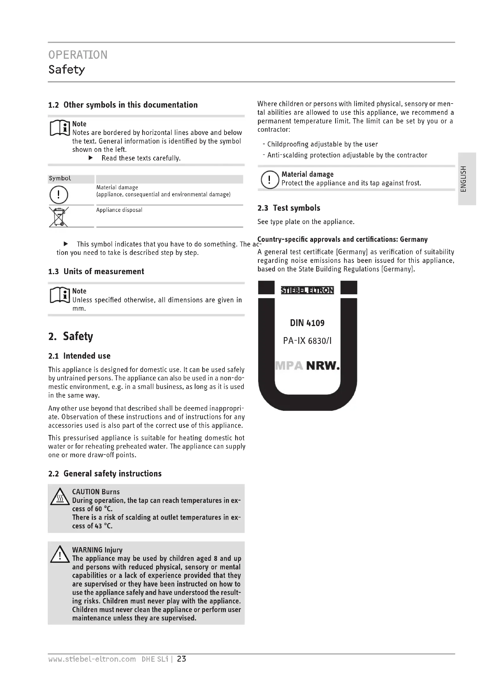
2.3 Test symbols
See type plate on the appliance.
This symbol indicates that you have to do something. The action you need to take is described step by step.
1.3 Units of measurement

Note
Unless specified otherwise, all dimensions are given in mm.
2. Safety
2.1 Intended use
This appliance is designed for domestic use. It can be used safely by untrained persons. The appliance can also be used in a non-domestic environment, e.g. in a small business, as long as it is used in the same way.
Any other use beyond that described shall be deemed inappropriate. Observation of these instructions and of instructions for any accessories used is also part of the correct use of this appliance.
This pressurised appliance is suitable for heating domestic hot water or for reheating preheated water. The appliance can supply one or more draw-off points.
2.2 General safety instructions

CAUTION Burns
During operation, the tap can reach temperatures in excess of 60^ .
There is a risk of scalding at outlet temperatures in excess of 43^

WARNING Injury
The appliance may be used by children aged 8 and up and persons with reduced physical, sensory or mental capabilities or a lack of experience provided that they are supervised or they have been instructed on how to use the appliance safely and have understood the resulting risks. Children must never play with the appliance. Children must never clean the appliance or perform user maintenance unless they are supervised.
Country-specific approvals and certifications: Germany
A general test certificate [Germany] as verification of suitability regarding noise emissions has been issued for this appliance, based on the State Building Regulations [Germany].
3. Appliance description
This appliance with full electronic control and output matching keeps the outlet temperature constant. The water is heated by the electronic control unit with motorised valve to precisely the selected temperature. This occurs regardless of the inlet temperature.
DHW temperature
The DHW outlet temperature can be variably adjusted. The selected temperature is displayed.
Heating system
The bare wire heating system has a pressure-tested copper casing. The heating system is suitable for hard and soft water areas; it has low susceptibility to scale build-up. This system ensures rapid and efficient DHW availability.

Note
The appliance is equipped with an air detector that largely prevents damage to the heating system. If, during operation, air is drawn into the appliance, the heater shuts down automatically for one minute, thereby protecting the heating system.
Display backlighting
The display features two-tone backlighting (green / amber).
Efficiency display
Green ECO backlighting indicates that the appliance is operating in a particularly economical way
- when the output is less than 80%
- when the maximum output is less than 80% while the inlet temperature is higher than 35^
- when the maximum output is less than 80% while the ECO function is switched on
Under all other operating conditions, the backlighting is amber.
Economy monitor
The appliance has an economy monitor. This is activated by pressing the appropriate key. It displays:
- Energy savings*
Water savings* - CO_2 savings*
- Energy consumption
-
Water consumption
-
Compared to hydraulic instantaneous water heaters. Calculation for a 3-person household with individual DHW requirements and usable energy requirements subject to VDI 2067. Electricity and water costs can be programmed individually.
4. Settings and displays
You can adjust the appliance via the user interface.
Inlet temperature information
If the inlet temperature is higher than the preferred temperature, e.g. if water has been preheated by solar energy, then the temperature display flashes and the second display indicates the inlet temperature. No further heating of the water occurs.
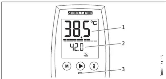
1 Temperature display flashes
2 Inlet temperature display
3 Scalding risk LED; red LED when the temperature setting >43^
Recommended setting for operation with a thermostatic valve
Set the temperature at the appliance to 60^ .
Following an interruption of the water supply
See chapter "Restarting"
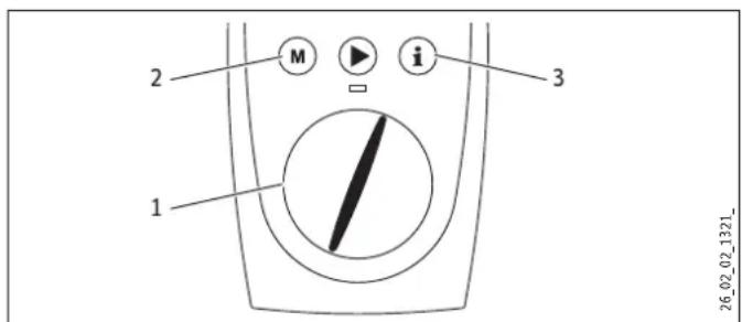
4.1 User interface on the appliance
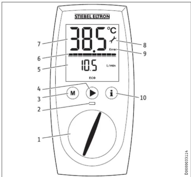
1 Temperature selector
2 Scalding risk LED
3 Memory key
4 Menu key, e.g. ECO
5 Additional value display
6 Heating output display
7 Temperature display
8 Service symbol
9 Fault symbol
10 Information key, economy menu
When the appliance is delivered the backlighting is set so that the screen is illuminated automatically as soon as you operate the selector or a key, or the appliance heats. If the selector or a key is not pressed or the appliance does not heat for 30 seconds, the backlighting switches off. You can also set the illumination to be on constantly.
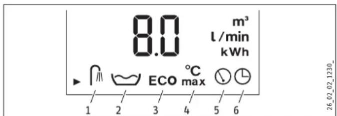
Symbols
1 Shower programs for good health
2 Automatic water volume control
3 ECO
4 Childproof setting
5 Additional value display
6 Time
4.2 Temperature setting
1 Temperature setting 20 - 60^ in steps of 0.5^ , OFF = heating system is switched off
2 Programmed temperature selection
3 Economy monitor selection
You can store a preferred temperature with memory key M.
Select the preferred temperature.
Press the M key for 2 seconds. The temperature display flashes once to confirm.
4.3 Economy monitor selection
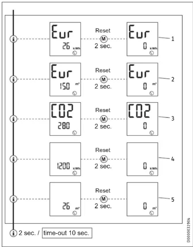
Example menu structure with currency in euros (Eur)
1 Energy saving
The energy saving in euros (Eur) in comparison to hydraulic instantaneous water heaters is calculated and displayed.
2 Water saving
The water saving in euros (Eur) in comparison to hydraulic instantaneous water heaters is calculated and displayed.
3 CO2 emissions
The CO2 saving in kg in comparison to hydraulic instantaneous water heaters is calculated and displayed.
4 Amount of energy
The amount of energy consumed in kWh is displayed.
5 Water consumption
The amount of water consumed in ^3 is displayed.
4.4 Appliance settings
Key to symbols

Press once START-menu
Press once Change menu
Hold for 2 seconds END

Change settings / scanning
Menu structure
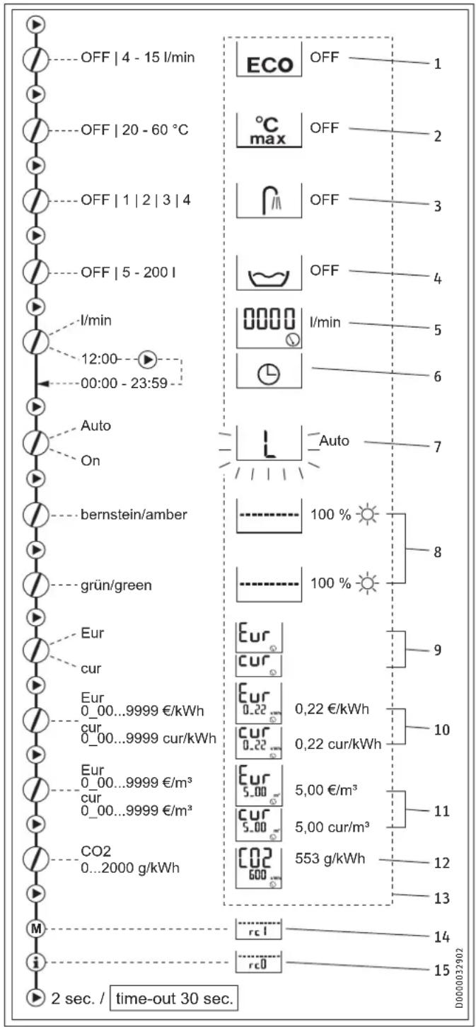
1 ECO water and energy saving function
The ECO function enables you to limit the flow rate to a maximum value.
ECO on = symbol on user interface
ECO off = no symbol on user interface
2 Childproofing
Childproofing allows you as a user to limit the adjustable temperature at the appliance to a maximum value. In service mode, the contractor can also set a temperature for anti-scalding protection (see chapter "Service mode"). This temperature then acts as the upper limit of the setting range for childproofing.
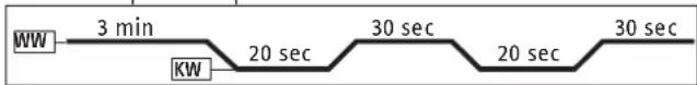
3 Shower programs for good health
The shower program for good health lets you choose from 4 different shower programs.
WW = domestic hot water, KW = cold water
A Cold prevention
To strengthen the body, we recommend you finish off with a cold shower; this will trigger a reflex in the body to warm up.
B Winter pick-me-up
An invigorating end to a winter shower with a final warm-up.
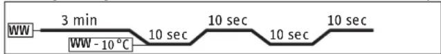
C Summer fitness program
The quick contrast shower to increase fitness with a final warm-up.
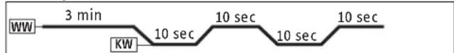
D Circulation program
Shower your arms and legs with cold water to boost circulation. Spray from the hands and feet towards the body. You can then repeat this process with warm water.
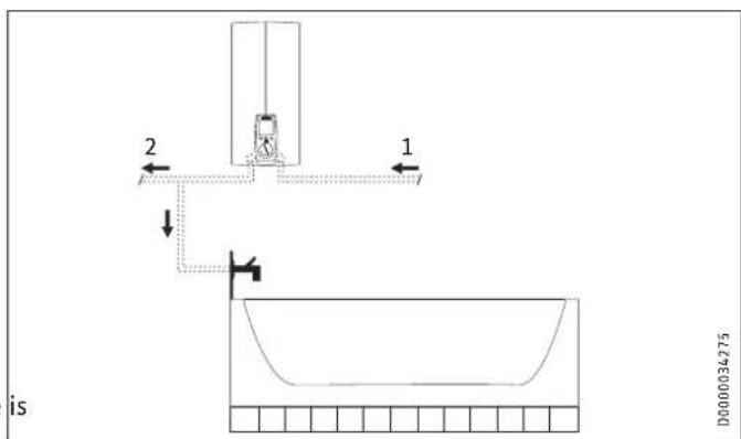
4 Automatic water volume control
The automatic water volume control allows you to limit the volume of water at a high flow rate. When the selected volume of water is reached, the control automatically reduces the flow rate. The preferred water temperature is maintained. The automatic water volume control must be enabled on each occasion prior to filling the bath. Example of filling a bath with 80 litres: When the bath has been filled with 80 litres, the control automatically reduces the flow rate to 4l / min .
5 Flow rate
You have the option of displaying the flow rate or the time.
6 Setting the time
You have the option of displaying the time or the flow rate. You can set a time from 00:00 h to 23:59 h. You will need to set the time again following a power interruption.
7 Adjusting the backlighting
You are able to adjust the display backlighting. If you select "Auto" the illumination will flash during the setting process.
- The backlighting switches on whenever the appliance heats and with any operation of the user interface.
- If there is no operation for 30 seconds the backlighting switches off.
- If you select "On" the backlighting will remain on constantly.
8 Adjusting the green/amber brightness
You can adjust the brightness of both backlighting colours individually.
9 Selecting the currency
Here you can select the currency you wish to display for the energy and water saving: Eur = cur = any other currency
10 Setting the electricity tariff
Here you can enter your particular electricity tariff in Eur/kWh or cur/kWh in order to calculate the energy saving.
11 Setting the water tariff
Here you can enter your particular water tariff in / ^3 or cur/m³ in order to calculate the water saving.
12 Setting the C02 emissions value
The factory default for the CO2 emissions calculation is 553 g CO2/kWh (source: "Reducing energy consumption and CO2 emissions through electrical domestic hot water supply", 2011). You can also set your own CO2 emissions value if required.
13 Resetting to factory defaults
Press keys M and i simultaneously for 2 seconds.
The default settings can be found in the dashed box in the diagram.
14 Parameter
This parameter is not relevant to this version of the appliance. It is not possible to adjust any settings.
15 Parameter
This parameter is not relevant to this version of the appliance. It is not possible to adjust any settings.
5. Cleaning, care and maintenance
- Never use abrasive or corrosive cleaning agents. A damp cloth is sufficient for cleaning the appliance.
- Check the taps/valves regularly. You can remove limescale deposits at the tap outlets using commercially available descaling agents.
6. Troubleshooting
| Fault Cause Remedy | ||
| The appliance will not start in spite of a fully open DHW valve. | There is no mains voltage. | Check the fuse/MCB in your fuse box/distribu-tion panel. |
| The aerator in the tap or shower head is scaled up or contaminated. | Clean and/or descale the aerator or shower head. | |
| The water supply has been interrupted. | Vent the appliance and the cold water inlet line (see chapter "Commis-sioning/ Restarting"). | |
| Cold water flows briefly while hot water is being drawn. | The air sensor detects air in the water and briefly switches the heater off. | The appliance restarts automatically after 1 minute. |
| Temperatures >43 °C. | Dynamic anti-scalding protection is activated. | Dynamic anti-scalding protection automatically ceases 2 minutes after draw-off has ended. |
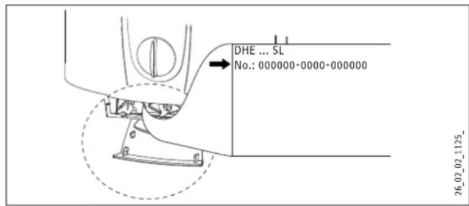
If you cannot remedy the fault, notify your heating contractor. To facilitate and speed up your enquiry, please provide the serial number from the type plate (000000-0000-000000):
INSTALLATION
7. Safety
Only a qualified contractor should carry out installation, commissioning, maintenance and repair of the appliance.
7.1 General safety instructions
We guarantee trouble-free function and operational reliability only if the original accessories and spare parts intended for the appliance are used.

Material damage
Observe the maximum inlet temperature. The appliance can be damaged by higher temperatures. You can limit the maximum inlet temperature by installing a central thermostatic valve (see chapter "Appliance description / Accessories").
7.2 Instructions, standards and regulations

Note
Observe all applicable national and local instructions and regulations, e.g. DIN 1988 / DIN EN 806 in Germany.
- The protection rating IP 25 (hoseproof) can only be ensured with a correctly fitted cable grommet.
- The specific electrical resistance of the water must not fall below that stated on the type plate. In a linked water network, observe the lowest electrical water resistance (see chapter "Specification / Application areas"). Your water supply utility will advise you of the specific electrical water resistance or conductivity.
8. Appliance description
8.1 Standard delivery
Delivered with the appliance:
- Mounting bracket
- Installation template
- 2 twin connectors
- Cross-piece
- Tee
- Flat gaskets
- Strainer
- Plastic profile washer
- Plastic connection pieces / installation aid
- Cover and back panel guides
8.2 Accessories
Remote controls
- FFB 1 SL - Wireless remote control Control from two locations
- FFB 2 SL - Wireless remote control
Wireless remote control unit as extension of the FFB 1 SL - FB 1 SL - Hardwired remote control Control only with remote control unit, suitable for self-supporting installation
Taps/valves
- MEKD - kitchen pressure tap
-MEBD-bath pressure tap
Plug G 1 / 2 A
The plugs are required if you use pressure taps for finished walls other than the ones recommended in the accessories.
Installation set for finished walls
- Solder fitting - copper pipe for solder connection 0.12mm
- Compression fitting - copper pipe
- Compression fitting - plastic pipe (suitable for Viega: Sanfix-Plus or Sanfix-Fosta)
Universal mounting frame
Mounting frame with electrical connections.
Pipe assembly for undersink appliances
This assembly for undersink installation is required if you need to have the water connections (G^3 / 8A) above the appliance.
Pipe assembly for offset installation
This pipe assembly with pipe bends is required if you need to have the appliance vertically offset against the water connection by approx. 90mm downwards.
Pipe assembly for replacing a gas water heater
This pipe assembly is required if the installation has existing gas water heater connections (cold water connection on the left and DHW connection on the right).
Pipe assembly DHB water plug-in couplings
2 water plug-in couplings allow the appliance to be connected to the available water plug-in connections of a DHB.
Load shedding relay (LR 1-A)
The load shedding relay which needs to be installed in the distribution board provides priority control for the instantaneous water heater when operating, for example, electric storage heaters simultaneously.
ZTA 3/4 - central thermostatic valve
Thermostatic valve for central premixing, for example for an instantaneous water heater with a solar thermal system.
INSTALLATION
Preparations
9. Preparations
Flush the water line thoroughly.
Taps/valves
Use suitable taps (see chapter "Appliance description / Accessories"). Open taps are not permitted.
A safety valve is not required.

Note
Never use the cross-piece to reduce the flow rate. It is intended to shut off the appliance.
Permissible water pipe materials
Cold water inlet pipe: Galvanised steel pipe, stainless steel pipe, copper pipe or plastic pipe
- DHW outlet pipe: Stainless steel pipe, copper pipe or plastic pipe

Material damage
If plastic pipework systems are used, take into account the maximum inlet temperature and the maximum pressure (see chapter "Specification / Data table").
Flow rate
Ensure that the flow rate (see chapter "Specification / Data table", On) for switching on the appliance is achieved.
Increase the mains water pressure if the required flow rate not achieved with the draw-off valve fully opened.
Flexible water connection lines
If the appliance is installed with flexible water connection lines, ensure that the pipe bends do not become twisted. Pipe bends have a bayonet fitting and are installed inside the appliance.
- Secure the back panel at the bottom with an additional screw.
9.1 Installation site

Material damage
Install the appliance in a room free from the risk of frost.
Always install the appliance vertically near the draw-off point.
The appliance is suitable for undersink and oversink installations.

Note
The appliance must be fitted to a wall with sufficient load-bearing capacity.

Undersink installation
Oversink installation
The appliances are prepared in the delivered condition:
- Power supply from below, installation on unfinished walls
Water connection, installation on unfinished walls - For the appliance with connected load changeover, the average connected load is preset.
INSTALLATION
Installation
10. Installation
This chapter describes installation in accordance with the factory settings.
For further installation options, see chapter "Installation alternatives".
Open the appliance.
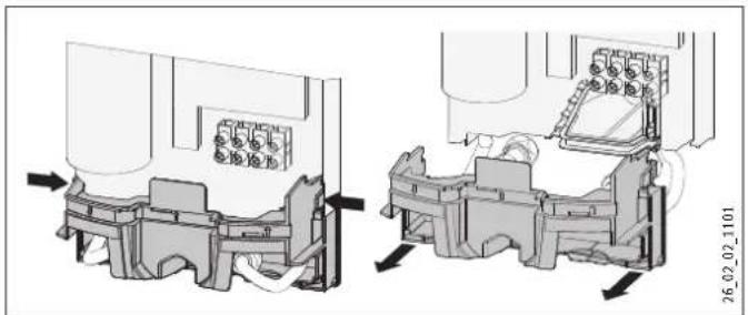
- Remove the back panel by pressing the two locking hooks and pulling the lower part of the back panel towards the front.
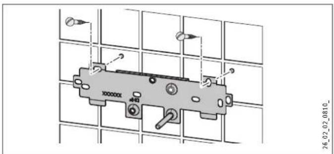
Mark out the holes for drilling with the installation tem If the appliance is to be installed with water connections for finished walls, also mark out the fixing hole in the lower part of the template.

- Drill the holes and secure the mounting bracket with 2 screws and 2 rawl plugs (screws and rawl plugs are not part of the standard delivery).
Note
If you are installing the appliance with flexible water connections, secure the back panel with a screw.
Fit the mounting bracket.
1 Installation aid
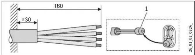
Prepare the power cable.
Making the water connection

Material damage
Carry out all water connection and installation work in accordance with regulations.
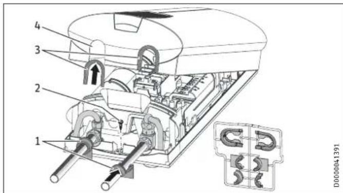
Seal and insert the twin connectors.
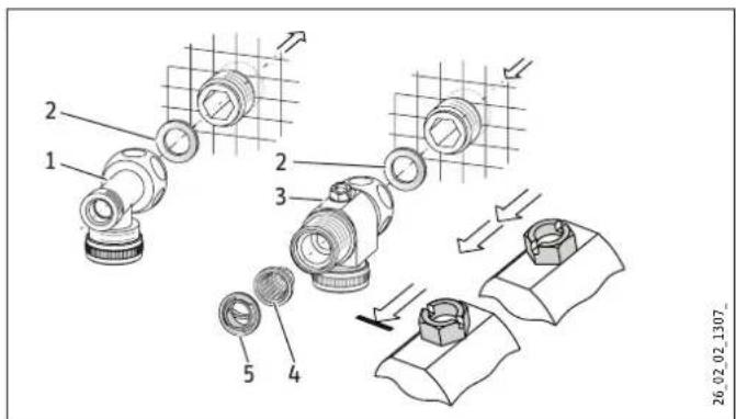
1 DHW with tee
2 Gasket
3 Cold water with cross-piece
4 Strainer
5 Profile washer
Fit the water connections.
Material damage
The strainer must be fitted for the appliance to function.
When replacing the appliance, check that the strainer is present.
Installing the appliance
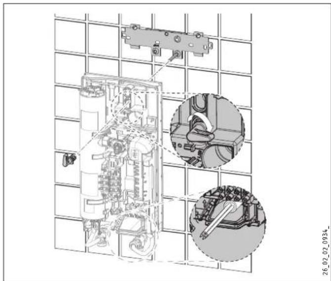
For easy installation, push the cable grommet of the upper electrical connection into the back panel from behind.
Remove the transport plugs from the water connections.
- Remove the fixing toggle from the upper part of the back panel.
- Route the power cable from behind through the cable grommet until it rests against the cable sheath. Align the power cable.
In the case of a cross-section >6mm^2 , enlarge the hole in the cable grommet.
Push the appliance over the threaded stud of the mounting bracket, so that it breaks through the soft seal. If necessary, use a screwdriver.
Push the fixing toggle onto the threaded stud of the mounting bracket.
Press the back panel firmly into place and lock the fixing to gle by turning it clockwise through 90^ .
Fit the pipes with flat gaskets onto the twin connectors.
Connecting the power supply

WARNING Electrocution Carry out all electrical connection and installation work in accordance with relevant regulations.

WARNING Electrocution Connection to the power supply is only permissible in the form of a permanent connection in conjunction with the removable cable grommet. Ensure that the appliance can be separated from the power supply by an isolator that disconnects all poles with at least 3mm contact separation.

WARNING Electrocution Ensure that the appliance is earthed.
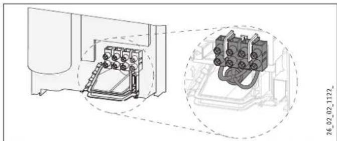
Connect the power cable to the mains terminal (see chapter "Specification / Wiring diagram"). The specified voltage must match the mains voltage.
Connected load options
Up to 3 connected load stages can be selected, subject to appliance type. The middle load is preset. If you wish to select a different load, please follow the steps below.
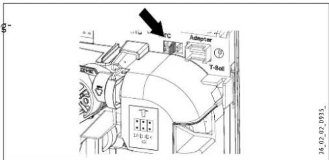
Select the connected load you require (see chapter "Specification / Data table").
Replug the coding card in accordance with the selected connected load.
Change the type plate. Tick the selected connected load. Please use a ballpoint pen to do this.
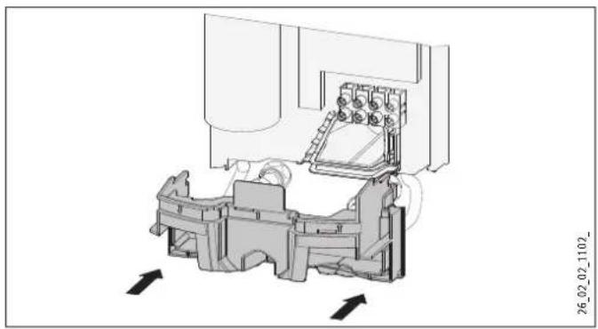
10.1 Completing the installation
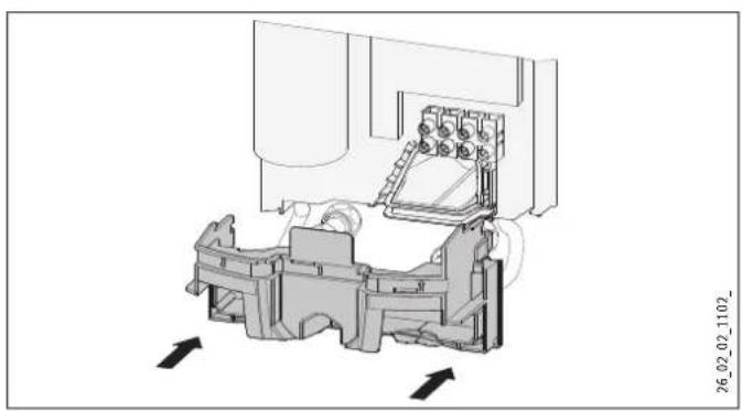
Fit the lower part of the back panel. Ensure that it clicks into place.
Align the mounted appliance by loosening the fixing toggle aligning the power supply and back panel, and then re-tightening the fixing toggle. If the back panel of the appliance is not flush, the appliance can be secured at the bottom with an additional screw.
10.2 Alternative installation methods
- Power supply from above for unfinished walls
- Power supply for finished walls
Large cross-section for power supply from below - Connecting a load shedding relay
Water installation for finished walls - Water installation for finished walls with solder / compression fitting
- Water installation for finished walls, fitting the appliance cover
- Installation of lower part of back panel with threaded fitting for finished walls
- Use of existing mounting bracket when replacing an appliance
- Installation with offset tiles
- Turned appliance cover
Operation with preheated water
Power supply from above for unfinished walls
Cut off the cable grommet for the power cable.
Push down the locking hook that secures the mains terminal, then remove the mains terminal.
- Reposition the mains terminal in the appliance from the bottom to the top and secure the mains terminal by sliding it under the locking hook.
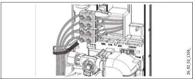
- Route the control wires below the wire guide.
Power cable for finished walls
Cut or break out the required entries in the back panel and appliance cover cleanly (for positions, see chapter "Specification / Dimensions and connections"). If necessary, use a file.
- Route the power cable through the cable grommet and connect it to the mains terminal.

Note
This type of connection changes the protection rating of the appliance.
Change the type plate. Cross out "IP 25" and mark the box "IP 24". Please use a ballpoint pen to do this.
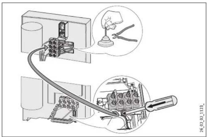
Large cross-section for power supply from below
If cables with a large cross-section are used, the cable grommet can be fitted after the appliance has been installed.
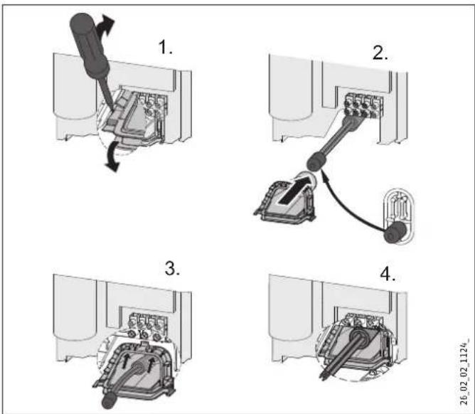
Before installing the appliance, use a screwdriver to push the cable grommet out.
- Push the cable grommet over the power cable. For this, use the installation aid. In the case of a cross-section >6mm^2 , enlarge the hole in the cable grommet.
Push the cable grommet into the back panel.
INSTALLATION
Installation
Connecting a load shedding relay
Install the load shedding relay in the distribution board in conjunction with other electric appliances, e.g. electric storage heaters. The relay responds when the instantaneous water heater starts. The load shedding relay is available as an accessory.

Material damage
Connect the phase that switches the load shedding relay to the indicated terminal of the mains terminal in the appliance (see chapter "Specification / Wiring diagram").
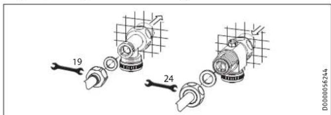
Water installation for finished walls
Suitable pressure-tested taps can be ordered as accessories.
1 Water plug
2 Pressure tap for finished walls
Fit the water plugs with gaskets to seal the connection below the plaster. With pressure taps listed in the accessories, the plugs and gaskets are part of the standard delivery.
Install the tap.
Place the lower part of the back panel under the connection pipes of the tap and push the lower part of the back panel into place.
Secure the connection pipes to the appliance.
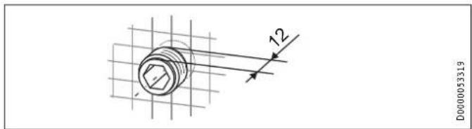
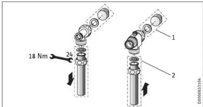
Water installation for finished walls with solder / compression fitting
You can connect copper or plastic pipes with solder fitting or compression fitting accessories.
The solder fitting with threaded fitting is suitable for 12mm copper pipes.
Push the union nuts over the connection pipes.
Solder the inserts to the copper pipes.
Push the lower part of the back panel under the connection pipes of the tap and click the lower part of the back panel into place.
Secure the connection pipes to the appliance.

Note
Observe the tap manufacturer's instructions.
Water installation for finished walls, fitting the appliance cover
1 Back panel guides
2 Screw
3 Cover guides
4 Knock-out
Cleanly break out the knock-outs in the appliance cover. If necessary, use a file.

Note
If the tap connection pipes are slightly offset, the appliance can be sealed using the tabs on the cover guides.
If the tap connection pipes are offset, do not fit any back panel guides.
If installing tap connection pipes which are not offset, break off the tabs on the cover guides.
Click the cover guides into place in the knock-outs.
Position the back panel guides on the pipes and push them together. Then push the guides until they are resting against the back panel.
Secure the back panel at the bottom with a screw.
Installation of lower part of back panel with threaded fitting for finished walls
You can install the lower part of the back panel after fitting the taps.
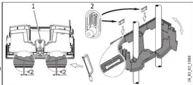
1 Screw
2 Connection pieces from the pack
Cut open the lower part of the back panel at the markings.
Fit the lower part of the back panel by bending it out at the sides and guiding it over the pipes.
Insert the connection pieces from behind into the lower part of the back panel.
- Click the lower part of the back panel into place.
- Secure the lower part of the back panel with a screw.
INSTALLATION
Installation
Mounting bracket for appliance replacement
Am existing Stiebel Eltron mounting bracket may be used when replacing appliances (except instantaneous water heater DHF).
Break through the back panel of the appliance for the threaded stud on the pre-installed mounting bracket.
DHF replacement
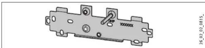
- Reposition the threaded stud on the mounting bracket (the stud has a self-tapping thread).
Rotate the mounting bracket through 180^ and mount it on the wall (the DHF logo is then turned towards the reader).
Installation with offset tiles
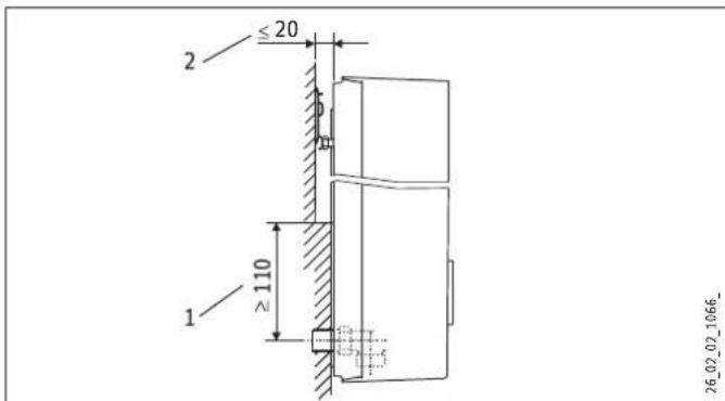
1 Minimum contact area of the appliance
2 Maximum tile offset
Adjust the wall clearance and lock the back panel with the fixing toggle by turning it clockwise through 90^ .
Turned appliance cover
The appliance cover can be turned for undersink installation.
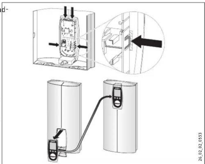
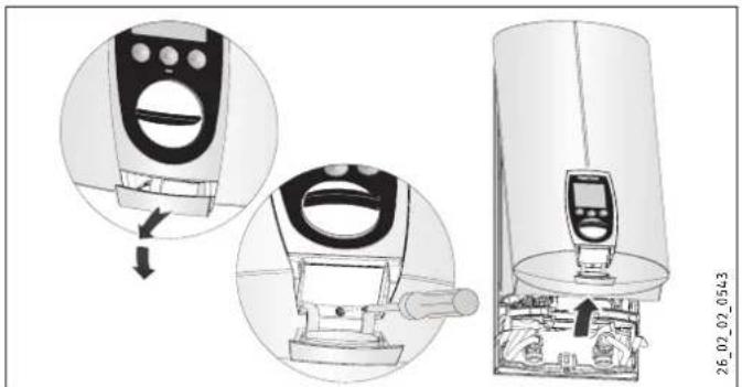
- Remove the programming unit from the appliance cover by pressing the locking hooks and taking out the programming unit.
Turn the appliance cover (not the appliance) and refit the programming unit, ensuring that all locking hooks click into place. When clicking the locking hooks into place, make sure you press against the inner side of the appliance cover (shaded area).
Plug the set value transducer cable into the PCB (see chapter "Commissioning"). - Hook the appliance cover back in at the bottom and pivot it up onto the back panel.
Ensure the all-round seal of the back panel sits tightly by pushing the cover gently forwards and back.
Secure the appliance cover.
Operation with preheated water
By installing a central thermostatic valve you will limit the maximum inlet temperature (see chapter "Appliance description / Accessories").
11. Commissioning

WARNING Electrocution Commissioning may only be carried out by an authorised contractor in accordance with safety regulations.
11.1 Commissioning
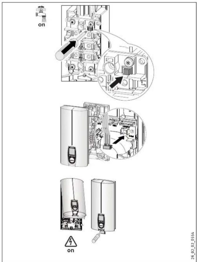
Open the cross-piece.
- Open and close all connected draw-off valves several times, until all air has been vented from the pipework and the appliance.
Carry out a tightness check.
Activate the safety switch (AE 3) by firmly pressing in the reset button (the appliance is delivered with the safety switch deactivated).
Push the set value transducer cable plug onto the PCB.
Fit the appliance cap and secure it with a screw.
Switch the mains power ON.
Check the function of the appliance.
Remove the protective foil from the user interface.
11.2 Recommissioning

Material damage
Following an interruption of the water supply the appliance must be recommissioned by carrying out the following steps, in order to prevent the destruction of the bare wire heating system.
Disconnect the appliance from the power supply removing the fuses/tripping the MCBs.
Open the tap for one minute until the appliance its upstream cold water inlet line are free of air.
Switch the mains power back ON again.
12. Service mode
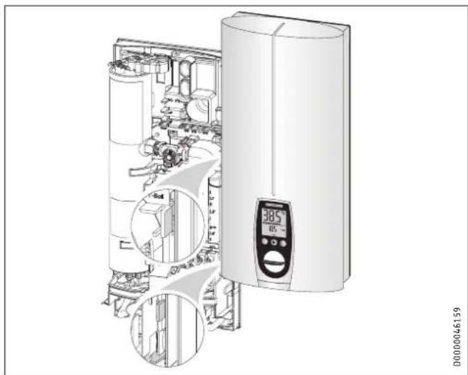
- Open the appliance cover and hook it on the side of the back panel.
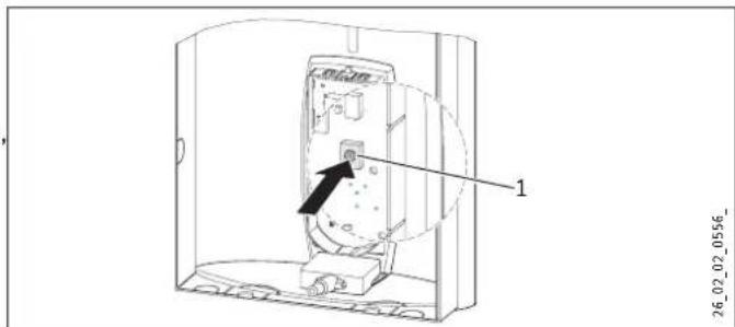
1 Service button for activating and deactivating service mode
Key to symbols

Press once START

Press once END
Change settings / scanning
In service mode you are able to call up and/or change the set temperature using the M key (60^)
oppliance handover
Explain the appliance function to users and familiarise them temperature using the M key (60^) with its operation.
Make the user aware of potential dangers, especially the risk of scalding.
Hand over these instructions.
Scanning the error menu
The error menu only appears if the appliance has a fault.
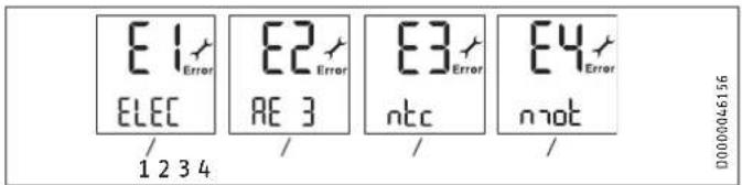
1 Electronic assembly symbol
Replace the electronic assembly.
2 Safety circuit symbol
Check the AE 3 connection; replace the AE 3 if required.
3 Outlet sensor symbol
- Check the outlet sensor connection; replace the outlet sensor required.
4 Motorised valve symbol
- Check the motorised valve connection; replace the motorised valve if required.
Scanning the control menu
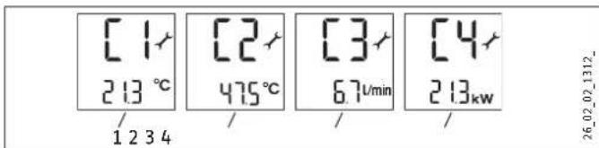
1 Inlet temperature symbol, shows the current inlet temperature (shows 1.0^ if the sensor is faulty).
2 Outlet temperature symbol, shows the current outlet temperature (shows 65.0^ if the sensor is faulty).
3 Flow rate symbol, shows the current flow rate.
4 Power consumption symbol, shows the current power consumption.
Scanning the appliance data menu
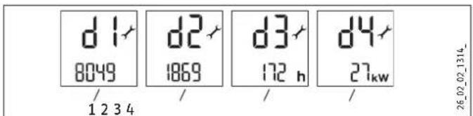
1 Service code symbol, information for service engineers.
2 Symbol for power supply runtime, accumulated runtime in days.
3 Heating hours symbol, accumulated heating time in hours.
4 Maximum output symbol The value shown may diverge by several kW from the rated output if mains voltages other than 400V prevail.
Setting the anti-scalding protection
Use the anti-scalding protection in places such as nurseries and hospitals. The temperature set here simultaneously acts as the upper limit of the temperature setting for childproofing (see chapter "Appliance settings").
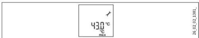
Setting range: 21 - 60^
Recommended setting 43^

Note
The anti-scalding protection setting can only be modified by your contractor. Simultaneously pressing the M + i key will not change the setting.
13. Shutting down
Isolate all poles of the appliance from the power supply.
Drain the appliance (see chapter "Maintenance").
14. Troubleshooting

WARNING Electrocution In order to check the appliance, it must be supplied with power.
Plug-in connections on the PCB
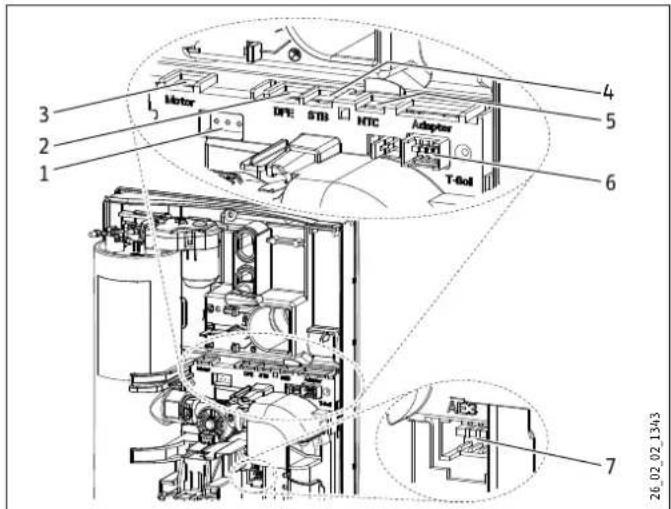
1 Diagnostic traffic light (3 LEDs)
2 Flow rate sensor DFE
3 Motorised valve
4 High limit safety cut-out STB
5 Outlet sensor NTC
6 Set temperature transducer
7 Safety switch AE 3; plug-in connection secured with locking tab.
| Possible indications of diagnostic traffic light (LED) | |||
| Red Illuminates in case of faults | |||
| Yellow Illuminates in heating mode | |||
| Green Flashing: appliance is supplied with mains power | |||
| Fault | Cause | Diagnostic traffic Light | Remedy |
| The appliance does not heat up / the set temperature is not reached. | There is no mains voltage. | No LED illuminates | Check the MCB/fuse in your fuse box. |
| The safety switch (AE 3) has responded. | No LED illuminates | Remove the cause of the fault.Proctect the system against overheating by opening a draw-off valve downstream of the appliance for one minute. This cools down the heating system. Activate the safety switch by pressing the pushbutton on the safety switch (see also chapter "Commissioning"). | |
| The PCB is faulty. | No LED illuminates | Check the PCB and replace if necessary. | |
| A phase has failed. | Flashing green LED, yellow LED on | Check the MCB/fuse in your fuse box. | |
| The inlet temperature is >55 °C. | Flashing green LED, red LED illuminates | Limit the inlet temperature. | |
| The flow rate sensor (DFE) is faulty or not attached. | Flashing green LED, yellow LED off | Check the connection of the flow rate sensor and replace if necessary. | |
| The heater is faulty. | Flashing green LED, yellow LED on | Check the heater and replace if necessary. | |
| The inlet sensor is faulty. | Flashing green LED, red LED illuminates | Replace the PCB. | |
| The outlet sensor is faulty. | Flashing green LED, red LED illuminates | Check the connection of the outlet sensor and replace if necessary. | |
| A fault in the safety PCB. | Flashing green LED, red LED only during draw-off | Connect the connecting cable from the safety switch and check the safety switch. | |
| A loose or faulty connecting cable to the set value trans-ducer. | Green LED flashes | Connect the connecting cable from the set value transducer and check the con-necting cable. | |
| The set value transducer is faulty. | Green LED flashes | Check the set value transducer and replace it if required. | |
| The display on the appliance is completely off. | A loose connecting cable to the set value transducer. | Green LED flashes | Connect the connecting cable at the set value transducer and check the connect-ing cable. |
| The programming PCB is faulty. | Green LED flashes | Check the programming unit and replace if necessary. | |
| The flow rate is too low. | The shower head / aerators are scaled up. | Descale or if necessary replace the shower head / aerators. | |
| The strainer is contaminated. | Clean the strainer. | ||
| The set value cannot be adjusted higher than 43 °C, nor can a differ-ent set temperature be selected. | Dynamic anti-scalding protec-tion is activated. | Green LED flashes | The dynamic anti-scalding protection is deactivated again 2 minutes after draw-off. |
| Childproofing and/or tempera-ture limiting is activated. | Green LED flashes | Disable temperature limiting. | |
| Cold water flows briefly during draw-off. | The flow rate (< 2 l/min) is too low. | The appliance restarts automatically when a flow rate of > 2.5 l/min has been detected. | |
| The air sensor detects the presence of air in the water and briefly switches the heater off. | The appliance restarts after one minute. | ||
15. Maintenance

WARNING Electrocution
Before any work on the appliance, disconnect all poles from the power supply.
Draining the appliance
You can drain the appliance for maintenance work or to protect it from frost.

CAUTION Scalding
Hot water may escape when draining the appliance.
Close the shut-off valve in the cold water supply line.
Open all draw-off valves.
Undo the water connections on the appliance.
Store the dismantled appliance in a room free from the risk of frost, as water residues remaining inside the appliance can freeze and cause damage.
16. Specification
16.1 Dimensions and connections
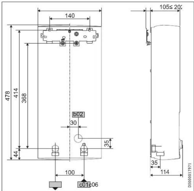
| b02 | Entry electrical cables I | ||
| c01 | Cold water inlet | Male thread | G 1/2 A |
| c06 | DHW outlet | Male thread | G 1/2 A |
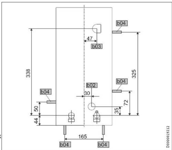
Alternative connection options
b02 Entry electrical cables I
b03 Entry electrical cables II
b04 Entry electrical cables III
16.2 Wiring diagram
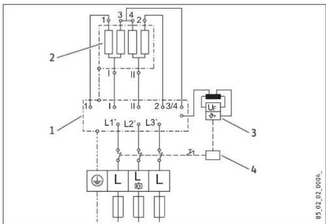
3/PE 380 - 415V
1 PowerPCB
2 Bare wire heating system
3 High limit safety cut-out
4 Safety switch
Priority control with load shedding relay (LR 1-A)
See also chapter "Appliance description / Accessories".
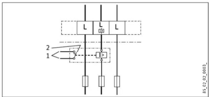
1 Control cable to the contactor of the second appliance (e.g. electric storage heater).
2 Control contact opens when switching the instantaneous water heater on.
16.3 Mixed water volume / outlet volume
The values are relative to a rated voltage of 400V . The mixed water volume and outlet volume are subject to the available supply pressure and the available mains voltage.
Available temperature approx. 38^ in the shower, for hand washing, filling the bath etc.
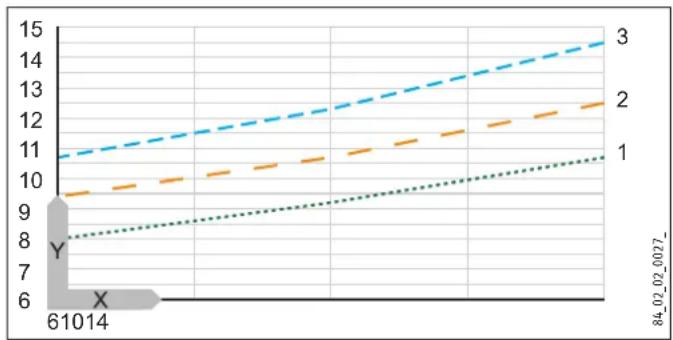
Outlet temperature approx. 60^ for the kitchen sink and when using thermostatic valves.
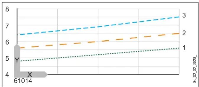
X Cold water inlet temperature in ^ C
Y Mixed water volume / outlet volume in l/min
1 18 kW
2 21 kW
3 24 kW
16.4 Applications / Conversion table
Specific electrical resistance and specific electrical conductivity, see "Data table".
| Standard specification at 15 °C | 20 °C | 25 °C | ||||||
| Spec. Resistance ρ ≥ | Spec. Conductivity σ ≤ | Spec. Resistance ρ ≥ | Spec. Conductivity σ ≤ | Spec. Resistance ρ ≥ | Spec. Conductivity σ ≤ | |||
| Ωcm | mS/m | μS/cm | Ωcm | mS/m | μS/cm | Ωcm | mS/m | |
| 900 | 111 | 1111 | 800 | 125 | 1250 | 735 | 136 | |
| 1000 | 100 | 1000 | 890 | 112 | 1124 | 815 | 123 | |
| 1100 | 91 | 909 | 970 | 103 | 1031 | 895 | 112 | |
| 1200 | 83 | 833 | 1070 | 93 | 935 | 985 | 102 | |
| 1300 | 77 | 769 | 1175 | 85 | 851 | 1072 | 93 | |
16.5 Pressure drop
Taps/valves
| Pressure drop at taps at flow rate of 10 L/min | ||
| Mono-lever mixer tap, approx. | MPa | 0.04 - 0.08 |
| Thermostatic valve, approx. | MPa | 0.03 - 0.05 |
| Hand shower, approx. | MPa | 0.03 - 0.15 |
Sizing the pipework
When calculating the size of the pipework, a pressure drop for the appliance of 0.1MPa is recommended.
16.6 Fault conditions
In case of faults, loads up to a maximum of 80^ at a pressure of 1.0MPa can occur temporarily in the installation.
16.7 Details on energy consumption
Product data complies with EU regulations relating to the Directive on the ecodesign of energy related products (ErP).
| DHE 18 SLi 25A DHE 18/21/24 SLi DHE 27 SLi | ||||
| 227492 227493 227494 | ||||
| Manufacturer | STIEBEL ELTRON | STIEBEL ELTRON | STIEBEL ELTRON | |
| Load profile | S | S | S | |
| Energy efficiency category | A | A | A | |
| Annual power consumption | kWh | 479 | 479 | 473 |
| Energy efficiency | % | 39 | 39 | 39 |
| Default temperature setting | °C | 60 | 60 | 60 |
| Sound power level | dB(A) | 15 | 15 | 15 |
| Special information on measuring the efficiency | None | Data at Pmax. | None | |
16.8 Data table
| DHE 18 SLi 25A DHE 18/21/24 SLi DHE 27 SLi | ||||||||||
| 227492 227493 227494 | ||||||||||
| Electrical details | ||||||||||
| Rated voltage | V | 380 | 400 | 415 | 380 | 400 | 415 | 380 | 400 | 415 |
| Rated output | kW | 16,2 | 18 | 19,4 | 16,2/19/21,7 | 18/21/24 | 19,4/22,6/25,8 | 24,4 | 27 | 29,1 |
| Rated current | A | 24,7 | 26 | 27 | 27,6/31,4/33,3 | 29/33/35 | 30,1/34,3/36,3 | 37,1 | 39 | 40,5 |
| Fuse | A | 25 | 25 | 32 | 32/32/35 | 32/32/35 | 32/35/40 | 40 | 40 | 40 |
| Phases | 3/PE | 3/PE | 3/PE | |||||||
| Frequency | Hz | 50/60 | 50/60 | 50/- | 50/60 | 50/60 | 50/- | 50/- | 50/- | 50/- |
| Max. mains impedance at 50Hz | Ω | 0,300 | 0,285 | 0,274 | 0,331 | 0,314 | 0,302 | 0,200 | 0,190 | 0,183 |
| Specific resistance ρ15 ≥ (at θcold ≤55 °C) | Ω cm | 900 | 900 | 900 | 900 | 900 | 900 | 900 | 900 | 900 |
| Specific conductivity σ15 ≤ (at θcold ≤55 °C) | μS/cm | 1111 | 1111 | 1111 | 1111 | 1111 | 1111 | 1111 | 1111 | 1111 |
| Connections | ||||||||||
| Water connection | G 1/2 A | G 1/2 A | G 1/2 A | |||||||
| Application limits | ||||||||||
| Max. permissible pressure | MPa | 1 | 1 | 1 | ||||||
| Max. inlet temperature for reheating | °C | 55 | 55 | 55 | ||||||
| Values | ||||||||||
| Max. permissible inlet temperature | °C | 65 | 65 | 65 | ||||||
| ON | l/min | >2,5 | >2,5 | >2,5 | ||||||
| Flow rate for pressure drop | l/min | 5,2 | 5,2/6,0/6,9 | 7,7 | ||||||
| Pressure drop at flow rate | MPa | 0,04 | 0,04/0,06/0,08 | 0,1 | ||||||
| DHW delivery | l/min | 9,2 | 9,2 / 10,7 / 12,3 | 13,8 | ||||||
| Δθ at DHW delivery | K | 28 | 28 | 28 | ||||||
| Hydraulic data | ||||||||||
| Rated capacity | I | 0,4 | 0,4 | 0,4 | ||||||
| Versions | ||||||||||
| Connected load options | X | |||||||||
| Temperature adjustment | °C | 20-60 | 20-60 | 20-60 | ||||||
| Protection class | 1 | 1 | 1 | |||||||
| Insulation block | Plastic | Plastic | Plastic | |||||||
| Heating system heat generator | Bare wire | Bare wire | Bare wire | |||||||
| Cap and back panel | Plastic | Plastic | Plastic | |||||||
| Colour | white | white | white | |||||||
| IP-Rating | IP25 | IP25 | IP25 | |||||||
| Dimensions | ||||||||||
| Height | mm | 478 | 478 | 478 | ||||||
| Width | mm | 225 | 225 | 225 | ||||||
| Depth | mm | 105 | 105 | 105 | ||||||
| Weights | ||||||||||
| Weight | kg | 4,5 | 4,5 | 4,5 | ||||||
Guarantee
The guarantee conditions of our German companies do not apply to appliances acquired outside of Germany. In countries where our subsidiaries sell our products a guarantee can only be issued by those subsidiaries. Such guarantee is only granted if the subsidiary has issued its own terms of guarantee. No other guarantee will be granted.
We shall not provide any guarantee for appliances acquired in countries where we have no subsidiary to sell our products. This will not affect warranties issued by any importers.
Environment and recycling
We would ask you to help protect the environment. After use, dispose of the various materials in accordance with national regulations.
UTILISATION
WAARSCHUWING IsetseI
WW = warm water, KW = koud water
$$ \text {E u r} = \epsilon $$
cur = currency (gewenste andere valuta)
10.1 Montage aflsuiten
8 Symbol servisu
9 Symbol chyby
10 Informaci tlaicitko - nabidka usporného programu
C Letni fitness program
$$ E u r = \epsilon $$
$$ \operatorname {c u r} = \text {c u r r e n c y (j i n a l i b o v o l n a m e n a)} $$
6 Prohasky Street | Port Melbourne VIC 3207
Tel. 03 9645-1833 | Fax 03 9645-4366
info@stiebel.com.au
www.stiebel.com.au
Austria
STIEBEL ELTRON Ges.m.b.H.
Eferdinger Str. 73 | 4600 Wels
Tel. 07242 47367-0 | Fax 07242 47367-42
info@stiebel-eltron.at
www.stiebel-eltron.at
Belgium
STIEBEL ELTRON bvba/sprl
Rm 102, F1, Yingbin-Yihao Mansion, No. 1
Yingbin Road
Panyu District | 511431 Guangzhou
Tel. 020 39162209 | Fax 020 39162203
info@stiebeleltron.cn
www.stiebeeltron.cn
Czech Republic
STIEBEL ELTRON spol. s r.o.
K Hajum 946 | 155 00 Praha 5 - Stodulky
Tel. 251116-111 | Fax 235512-122
Urzhumskaya street 4,
building 2 | 129343 Moscow
Tel. 0495 7753889 | Fax 0495 7753887
info@stiebel-eltron.ru
www.stiebel-eltron.ru
Slovakia
TATRAMAT - ohrieva vody s.r.o.
Hlavna 1 | 058 01 Poprad
Tel. 052 7127-125 | Fax 052 7127-148
info@stiebel-eltron.sk
www.stiebel-eltron.sk
Switzerland
STIEBEL ELTRON AG
Industrie West
Gass 8 | 5242 Lupfig
Tel. 056 4640-500 | Fax 056 4640-501
info@stiebel-eltron.ch
www.stiebel-eltron.ch
Thailand
STIEBEL ELTRON Asia Ltd.
469 Moo 2 Tambol Klong-jik
Amphur Bangpa-In l 13160 Ayutthaya
Tel. 035 220088 | Fax 035 221188
info@stiebeeltronasia.com
www.stiebeeltronasia.com
United Kingdom and Ireland
STIEBEL ELTRON UK Ltd.
Unit 12 Stadium Court
Stadium Road | CH62 3RP Bromborough
Tel. 0151 346-2300 | Fax 0151 334-2913
info@stiebel-eltron.co.uk
www.stiebel-eltron.co.uk
United States of America
STIEBEL ELTRON, Inc.
17 West Street | 01088 West Hatfield MA
Tel. 0413 247-3380 | Fax 0413 247-3369
info@stiebel-eltron-usa.com
www.stiebel-eltron-usa.com