DIVAcondens F24 - Boiler FERROLI - Free user manual and instructions
Find the device manual for free DIVAcondens F24 FERROLI in PDF.
Frequently Asked Questions - DIVAcondens F24 FERROLI
User questions about DIVAcondens F24 FERROLI
0 question about this device. Answer the ones you know or ask your own.
Ask a new question about this device
Download the instructions for your Boiler in PDF format for free! Find your manual DIVAcondens F24 - FERROLI and take your electronic device back in hand. On this page are published all the documents necessary for the use of your device. DIVAcondens F24 by FERROLI.
USER MANUAL DIVAcondens F24 FERROLI
Panel
fig.1 - Panel de control
Leyenda del panel fig. 1
- Carefully read and follow the instructions contained in this instruction booklet.
After boiler installation, inform the user regarding its operation and give him this manual, which is an integral and essential part of the product and must be kept with care for future reference. - Installation and maintenance must be carried out by professionally qualified personnel, in compliance with the current regulations and according to the manufacturer's instructions. Do not carry out any operation on the sealed control parts.
- Incorrect installation or inadequate maintenance can result in damage or injury. The Manufacturer declines any liability for damage due to errors in installation and use, or failure to follow the instructions.
- Before carrying out any cleaning or maintenance operation, disconnect the unit from the electrical power supply using the switch and/or the special cut-off devices.
- In case of a fault and/or poor operation, deactivate the unit and do not try to repair it or directly intervene. Contact professionally qualified personnel. Any repair/replacement of the products must only be carried out by qualified personnel using original replacement parts. Failure to comply with the above could affect the safety of the unit.
- This unit must only be used for its intended purpose. Any other use is deemed improper and therefore hazardous.
- The packing materials are potentially hazardous and must not be left within the reach of children.
- The unit must not be used by people (including children) with limited physical, sensory or mental abilities or without experience and knowledge of it, unless instructed or supervised in its use by someone responsible for their safety.
- The unit and its accessories must be appropriately disposed of, in compliance with the current regulations.
The images given in this manual are a simplified representation of the product. In this representation there may be slight and insignificant differences with respect to the product supplied.

THE CE MARKING CERTIFIES THAT THE PRODUCTS MEET THE ESSENTIAL REQUIREMENTS OF THE RELEVANT DIRECTIVES IN FORCE.
THE DECLARATION OF CONFORMITY MAY BE REQUESTED FROM THE MANUFACTURER.
2. OPERATING INSTRUCTIONS
2.1 Introduction
Dear Customer,
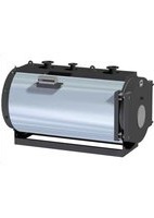
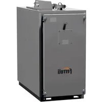
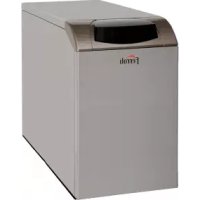
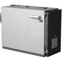
DIVAcondens F24/F28 is a high-efficiency sealed chamber condensing heat generator for heating and hot water production running on natural gas or LPG, and equipped with a microprocessor control system.
THIS UNIT IS IDEAL FOR COMBINING WITH CONVENTIONAL HIGH TEMPERATURE SYSTEMS. IT CANNOT BE COMBINED OR INSTALLED WITH DIRECT DELIVERY TO LOW TEMPERATURE RADIANT PANEL SYSTEMS. 2.2 Control panel

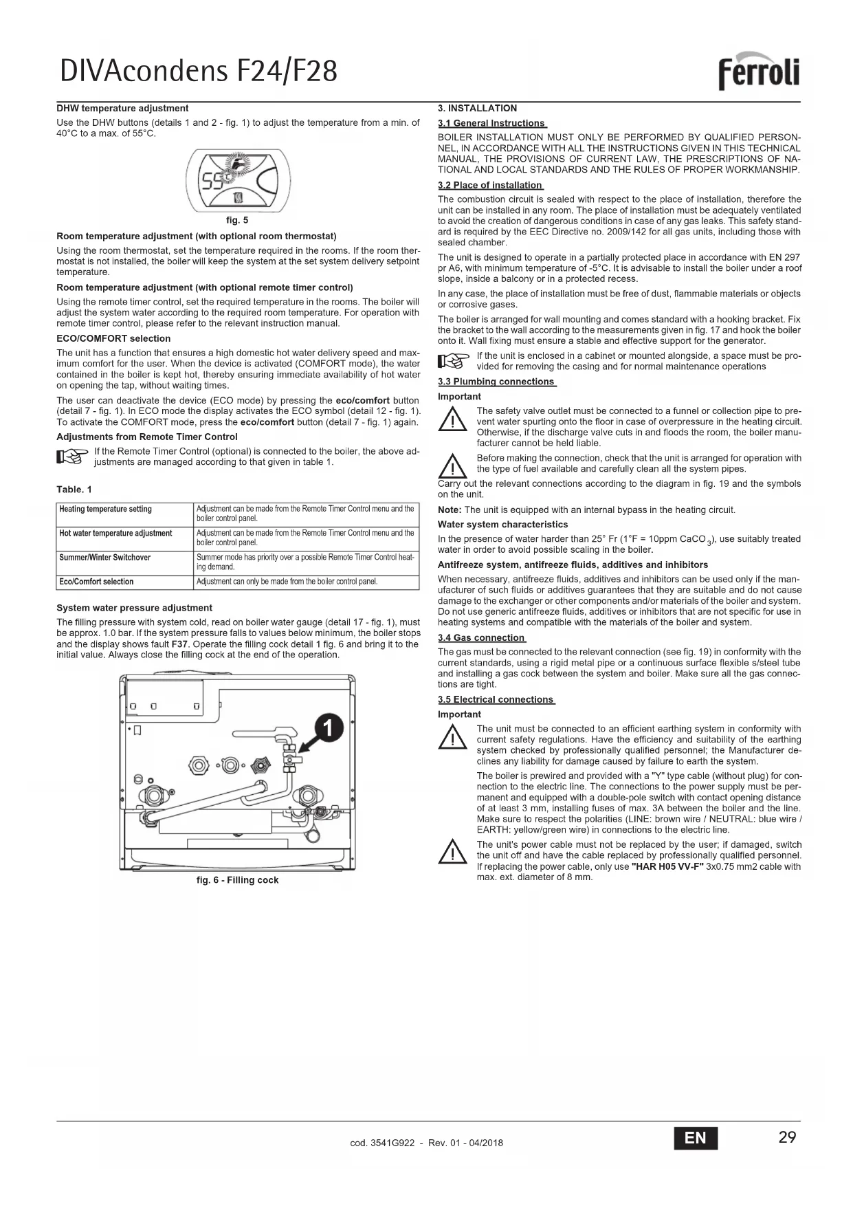
Panel
fig.1 - Control panel
Panel key fig. 1
1 DHW temperature setting decrease button
2 DHW temperature setting increase button
3 Heating system temperature setting decrease button
4 Heating system temperature setting increase button
5 Display
6 Summer/Winter mode selection - Reset button
7 Unit On/Off - Economy/Comfort mode selection button
8 DHW symbol
9 DHW mode
10 Summer mode
11 Multifunction
12 Eco (Economy) mode
13 Heating
14 Heating symbol
15 Burner lit and actual power level
17 Water gauge
Indication during operation
Heating
A heating demand (generated by the Room Thermostat or Remote Timer Control) is indicated by flashing of the hot air above the radiator on the display.
The display (detail 11 - fig. 1) shows the actual heating delivery temperature and, during heating standby time, the message "d2".
Domestic hot water (DHW)
A DHW demand (generated by drawing domestic hot water) is indicated by flashing of the hot water under the tap on the display.
The display (detail 11 - fig. 1) shows the actual DHW outlet temperature and, during DHW standby time, the message "d1".
Comfort
A Comfort demand (reinstatement of temperature inside the boiler) is indicated by flashing of the water under the tap on the display. The display (detail 11 - fig. 1) shows the actual temperature of the water in the boiler.
Fault
In case of a fault (see cap. 4.4) the display shows the fault code (detail 11 - cap. 4.4) and during safety pause times the message "d3".
2.3 Lighting and shutdown
Connection to the power supply
During the first 5 seconds the display will also show the card software release.
- Open the gas cock ahead of the boiler.
The boiler is now ready to function automatically whenever domestic hot water is drawn or in case of a heating demand (generated by Room Thermostat or Remote Temperature Control).
Switching the boiler off and on
Press the On/Off button (detail 7 - fig. 1) for 5 seconds.

fig. 2 -Turning the boiler off
When the boiler is switched off, the electronic board is still powered. Domestic hot water and heating are disabled. The antifreeze system remains activated. To relight the boiler, press the On/Off button (detail 7 fig. 1) again for 5 seconds.

fig. 3
The boiler will be immediately ready to work whenever domestic hot water is drawn or in case of a heating demand (generated by the Room Thermostat or the Remote Timer control).

The antifreeze system does not work when the power and/or gas to the unit are turned off. To avoid damage caused by freezing during long shutdowns in winter, it is advisable to drain all water from the boiler, the DHW circuit and the heating system water; or drain just the DHW circuit and add a suitable anti-freeze to the heating system, as prescribed in sec. 3.3.
2.4 Adjustments
Summer/Winter Swithchover
Press the summer/winter button (detail 6 - fig.1) for 2 seconds.
The display activates the Summer symbol (detail 10 - fig. 1): the boiler will only deliver domestic hot water. The antifreeze system remains activated.
To deactivate the Summer mode, press the summer/winter button (detail 6 - fig. 1) again for 2 seconds.
Heating temperature adjustment
Use the heating buttons (details 3 and 4 - fig. 1) to adjust the temperature from a min. of 30^ to a max. of 80^ .

fig.4
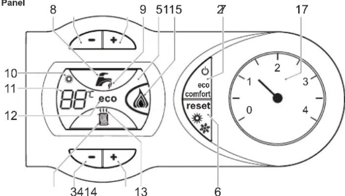
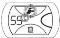
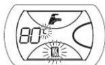
DHW temperature adjustment
Use the DHW buttons (details 1 and 2 - fig. 1) to adjust the temperature from a min. of 40^ to a max. of 55^ .
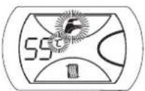
fig.5
Room temperature adjustment (with optional room thermostat)
Using the room thermostat, set the temperature required in the rooms. If the room thermostat is not installed, the boiler will keep the system at the set system delivery setpoint temperature.
Room temperature adjustment (with optional remote timer control)
Using the remote timer control, set the required temperature in the rooms. The boiler will adjust the system water according to the required room temperature. For operation with remote timer control, please refer to the relevant instruction manual.
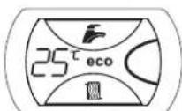
ECO/COMFORT selection
The unit has a function that ensures a high domestic hot water delivery speed and maximum comfort for the user. When the device is activated (COMFORT mode), the water contained in the boiler is kept hot, thereby ensuring immediate availability of hot water on opening the tap, without waiting times.
The user can deactivate the device (ECO mode) by pressing the eco/comfort button (detail 7 - fig. 1). In ECO mode the display activates the ECO symbol (detail 12 - fig. 1). To activate the COMFORT mode, press the eco/comfort button (detail 7 - fig. 1) again.
Adjustments from Remote Timer Control

If the Remote Timer Control (optional) is connected to the boiler, the above adjustments are managed according to that given in table 1.
Table.1
| Heating temperature setting | Adjustment can be made from the Remote Timer Control menu and the boiler control panel. |
| Hot water temperature adjustment | Adjustment can be made from the Remote Timer Control menu and the boiler control panel. |
| Summer/Winter Swithover | Summer mode has priority over a possible Remote Timer Control heating demand. |
| Eco/Comfort selection | Adjustment can only be made from the boiler control panel. |
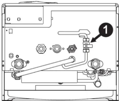
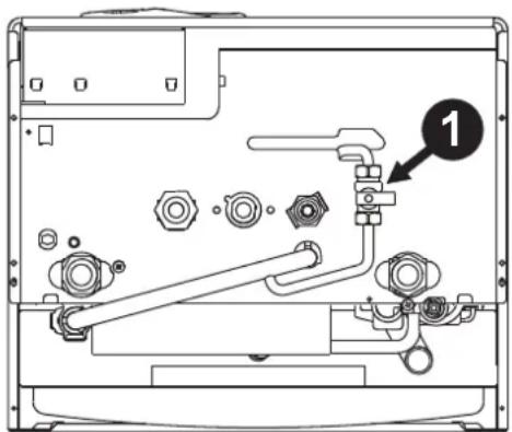
System water pressure adjustment
The filling pressure with system cold, read on boiler water gauge (detail 17 - fig. 1), must be approx. 1.0 bar. If the system pressure falls to values below minimum, the boiler stops and the display shows fault F37. Operate the filling cock detail 1 fig. 6 and bring it to the initial value. Always close the filling cock at the end of the operation.
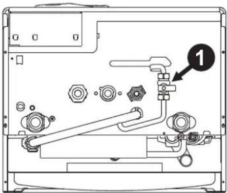
fig.6-Filling cock
3. INSTALLATION
3.1 General Instructions
BOILER INSTALLATION MUST ONLY BE PERFORMED BY QUALIFIED PERSONNEL, IN ACCORDANCE WITH ALL THE INSTRUCTIONS GIVEN IN THIS TECHNICAL MANUAL, THE PROVISIONS OF CURRENT LAW, THE PRESCRIPATIONS OF NATIONAL AND LOCAL STANDARDS AND THE RULES OF PROPER WORKMANSHIP.
3.2 Place of installation
The combustion circuit is sealed with respect to the place of installation, therefore the unit can be installed in any room. The place of installation must be adequately ventilated to avoid the creation of dangerous conditions in case of any gas leaks. This safely standard is required by the EEC Directive no. 2009/142 for all gas units, including those with sealed chamber.
The unit is designed to operate in a partially protected place in accordance with EN 297 pr A6, with minimum temperature of -5^ . It is advisable to install the boiler under a roof slope, inside a balcony or in a protected recess.
In any case, the place of installation must be free of dust, flammable materials or objects or corrosive gases.
The boiler is arranged for wall mounting and comes standard with a hooking bracket. Fix the bracket to the wall according to the measurements given in fig. 17 and hook the boiler onto it. Wall fixing must ensure a stable and effective support for the generator.

If the unit is enclosed in a cabinet or mounted alongside, a space must be provided for removing the casing and for normal maintenance operations
3.3 Plumbing connections
Important
The safety valve outlet must be connected to a funnel or collection pipe to prevent water spurting onto the floor in case of overpressure in the heating circuit. Otherwise, if the discharge valve cuts in and floods the room, the boiler manufacturer cannot be held liable.
Before making the connection, check that the unit is arranged for operation with the type of fuel available and carefully clean all the system pipes.
Carry out the relevant connections according to the diagram in fig. 19 and the symbols on the unit.
Note: The unit is equipped with an internal bypass in the heating circuit.
Water system characteristics
In the presence of water harder than 25^ Fr (1^ = 10ppm CaCO, use suitably treated water in order to avoid possible scaling in the boiler.
Antifreeze system, antifreeze fluids, additives and inhibitors
When necessary, antifreeze fluids, additives and inhibitors can be used only if the manufacturer of such fluids or additives guarantees that they are suitable and do not cause damage to the exchanger or other components and/or materials of the boiler and system. Do not use generic antifreeze fluids, additives or inhibitors that are not specific for use in heating systems and compatible with the materials of the boiler and system.
3.4 Gas connection
The gas must be connected to the relevant connection (see fig. 19) in conformity with the current standards, using a rigid metal pipe or a continuous surface flexible s/steel tube and installing a gas cock between the system and boiler. Make sure all the gas connections are tight.
3.5 Electrical connections
Important
The unit must be connected to an efficient earthing system in conformity with current safety regulations. Have the efficiency and suitability of the earthing system checked by professionally qualified personnel; the Manufacturer declines any liability for damage caused by failure to earth the system.
The boiler is prewired and provided with a "Y" type cable (without plug) for connection to the electric line. The connections to the power supply must be permanent and equipped with a double-pole switch with contact opening distance of at least 3mm , installing fuses of max. 3A between the boiler and the line. Make sure to respect the polarities (LINE: brown wire / NEUTRAL: blue wire / EARTH: yellow/green wire) in connections to the electric line.
The unit's power cable must not be replaced by the user; if damaged, switch the unit off and have the cable replaced by professionally qualified personnel. If replacing the power cable, only use "HAR H05 VV-F" 3x0.75 mm2 cable with max. ext. diameter of 8 mm.
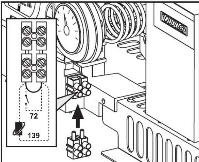
Room thermostat (optional)

IMPORTANT: THE ROOM THERMOSTAT MUST HAVE VOLTAGE-FREE CONTACTS. CONNECTING 230 V TO THE ROOM THERMOSTAT TERMINALS WILL PERMANENTLY DAMAGE THE ELECTRONIC BOARD.
When connecting time controls or a timer, do not take the power supply for these devices from their breaking contacts. Their power supply must be by means of direct connection from the mains or with batteries, depending on the kind of device.
Accessing the electrical terminal block
The electrical terminal block can be accessed after removing the casing. The arrangement of the terminals for the various connections is also given in the wiring diagram in fig. 24.
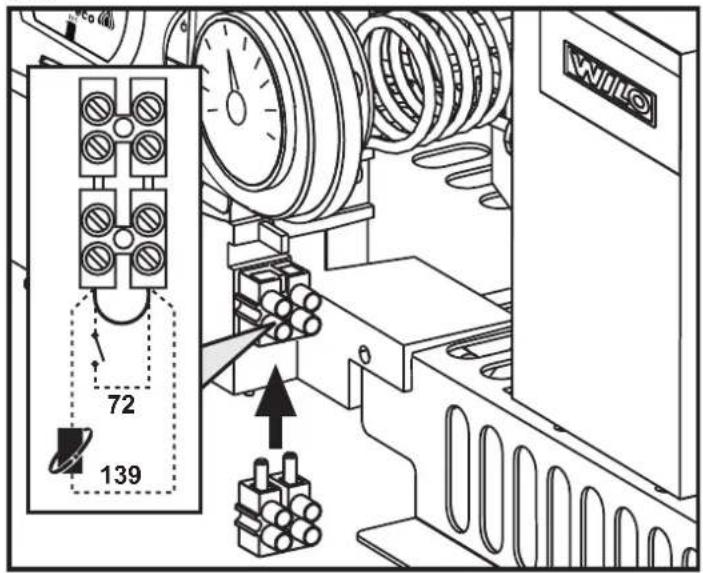
fig. 7 - Accessing the terminal block
3.6 Fume ducts
Important
The unit is a "C type" with sealed chamber and forced draught, the air inlet and fume outlet must be connected to one of the following extraction/suction systems. The unit is approved for operation with all the Cny flue configurations given on the dataplate. Some configurations may be expressly limited or not permitted by law, standards or local regulations. Before installation, check and carefully follow the instructions. Also, comply with the instructions on the positioning of wall and/or roof terminals and the minimum distances from windows, walls, ventilation openings, etc.
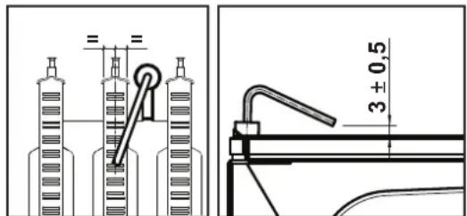
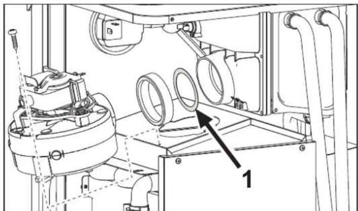
Baffles
Boiler operation requires fitting the baffles supplied with the unit, according to the following tables.
Before inserting the fume outlet pipe, it is therefore necessary to check there is the right diaphragm (when it is to be used) and that it is correctly positioned.
To replace the baffle (rif. 1 - fig. 8), proceed as indicated in fig. 8.

fig. 8

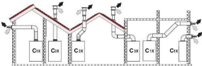
Connection with coaxial pipes
fig. 9 - Examples of connection with coaxial pipes ( = Air / = Fuses)
Table.2 - Typology
| Type Description | |
| C1X | Wall horizontal exhaust and inlet |
| C3X | Roof vertical exhaust and inlet |
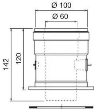
For coaxial connection, fit the unit with one of the following starting accessories. For the wall hole dimensions, refer to the figure on the cover. Any horizontal sections of the fume exhaust must be kept sloping slightly towards the boiler, to prevent possible condensate from flowing back towards the outside and causing dripping.


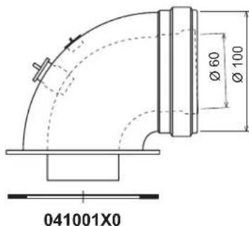
fig. 10 - Starting accessory for coaxial ducts
Table. 3 - Baffles for coaxial ducts
| DIVAcondens F24 | Coaxial 60/100 Coaxial | 80/125 | ||
| Max. permissible length 6 m 12 m | ||||
| Reduction factor 90° bend 1 m 0.5 m | ||||
| Reduction factor 45° bend 0.5 m 0.25 m | ||||
| Baffle to use | 0÷2 m Ø | 450÷6 m Ø 45 | ||
| 2÷4 m Ø | 50 | 6÷12 m | no baffle | |
| 4÷6 m | no baffle | |||
| DIVAcondens F28 | Coaxial 60/100 Coaxial | 80/125 | ||
| Max. permissible length | 4 m | 12 m | ||
| Reduction factor 90° bend 1 m 0.5 m | ||||
| Reduction factor 45° bend 0.5 m 0.25 m | ||||
| Baffle to use | 0 ÷ 2 m | Ø 50 | 0 ÷ 6 m Ø $0 | |
| 2 ÷ 4 m | no baffle | 6 ÷ 12 m | no baffle | |
Connection with separate pipes


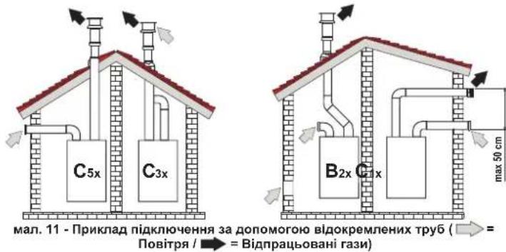
fig. 11 - Examples of connection with separate pipes ( = Air / = Fumes)
Table. 4 - Typology
| Type Description | |
| C1X | Wall horizontal exhaust and intake. The inlet/outlet terminals must be concentric or close enough to be undergo similar wind conditions (within 50 cm) |
| C3X | Roof vertical exhaust and intake. Inlet/outlet terminals like for C12 |
| C5X | Wall or roof exhaust and intake separate or in any case in areas with different pressures. The exhaust and intake must not be positioned on opposite walls. |
| C6X | Intake and exhaust with separately certified pipes (EN 1856/1) |
| B2X | Intake from installation room and wall or roof exhaustIMPORTANT - THE ROOM MUST BE PROVIDED WITH APPROPRIATE VENTILATION |
For connection of the separate ducts, fit the unit with the following starting accessory:
041039x0
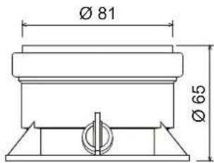
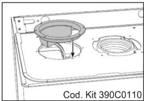
fig. 12 - Starting accessory for separate ducts
Before proceeding with installation make sure the maximum permissible length has not been exceeded, by means of a simple calculation:
- Completely establish the layout of the system of split flues, including accessories and outlet terminals.
- Consult the table 6 and identify the losses in meq (equivalent metres) of every component, according to the installation position.
- Check that the sum total of losses is less than or equal to the maximum permissible length in table 5.
Table. 5 - Baffles for separate ducts
| Separate ducts | ||
| Max. permissible length | 55 m_eq | |
| Baffle to use | 0 ÷ 15 m_12 | Ø 45 |
| 15 ÷ 35 m_22 | Ø 50 | |
| 35 ÷ 55 m_32 | No baffle | |
Table. 6 - Accessories
| Losses in \(m_{eq}\) | |||||
| Air inlet | Fume exhaust | ||||
| Vertical Horizontal | |||||
| ∅ 80 | PIPE | 1 m M/F 1KWMA83W 1.0 1.6 | 2.0 | ||
| BEND | 45° M/F 1KWMA85W 1.2 1.8 | ||||
| 90° M/F 1KWMA01W 1.5 2.0 | |||||
| PIPE SECTION | with test point 1KWMA70W 0.3 | 0.3 | |||
| TERMINAL | air, wall | 1KWMA85A 2.0 | - | ||
| fumes, wall with antiwind | 1KWMA86A | - | 5.0 | ||
| FLUE | Split air/fumes 80/80 | 010027X0 | - | 12.0 | |
| Fume outlet only Ø80 010026 | x0 + 1KWMA86U | - | 4.0 | ||
| ∅ 60 | PIPE | 1 m M/F 1KWMA89W | 6.0 | ||
| BEND | 90° M/F 1KWMA88W | 4.5 | |||
| REDUCTION | 80/60 | 041050X0 | 5.0 | ||
| TERMINAL | fumes, wall with antiwind | 1KWMA90A | 7.0 | ||
| ! | ATTENTION: CONSIDER THE HIGH PRESSURE LOSSES OF Ø60 ACCESSORIES;USE THEM ONLY IF NECESSARY AND AT THE LAST FUME EXHAUST SECTION. | ||||
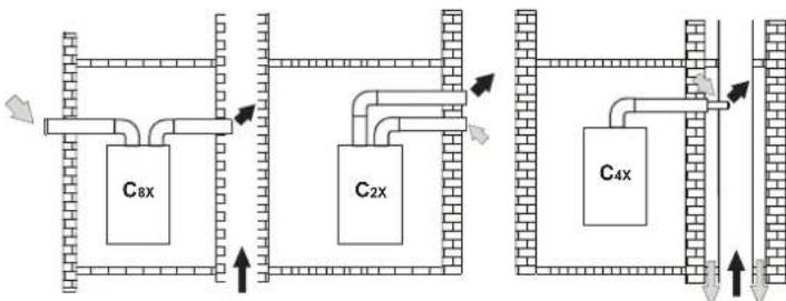
Connection to collective flues
fig. 13 - Examples of connection to flues ( = Air / = Fieses)
Table. 7 - Typology
| Type | Description |
| C2X | Intake and exhaust in common flue (intake and exhaust in same flue) |
| C4X | Intake and exhaust in common and separate flues , but undergoing similar wind conditions |
| C8X | Exhaust in single or common flue and wall intake |
| B3X | Intake from installation room by means of concentric duct (that encloses the exhaust) and exhaust in common flue with natural draught IMPORTANT - THE ROOM MUST BE PROVIDED WITH APPROPRIATE VENTILATION |
If the boiler is to be connected DIVAcondens F24/F28 to a collective flue or a single flue with natural draught, the flue or chimney must be expressly designed by professionally qualified technical personnel in conformity with the current regulations and be suitable for sealed chamber units equipped with fan.
4. SERVICE AND MAINTENANCE
4.1 Adjustments
Gas conversion
The unit can work on natural gas or LPG and is factory-set for use with one of these two gases, as clearly shown on the packing and data plate. Whenever a different gas to that for which the unit is arranged has to be used, the special conversion kit will be required, proceeding as follows:
- Disconnect the power supply ahead of the boiler and close the gas cock;
- Replace the nozzles at the main burner and pilot burner, fitting the nozzles indicated in the technical data table in cap. 5, depending on the type of gas used
- Connect the power supply ahead of the boiler and open the gas cock;
4.Modify the parameter for the type of gas:
-put the boiler in standby mode
press the DHW buttons details 1 and 2 - fig. = 1 for 10 seconds: the display shows "b01" flashing.
- press the DHW buttons details 1 and 2 - fig. 1) to set parameter 00 (for operation with natural gas) or 01 (for operation with LPG).
-press the DHW buttons details 1 and 2 - fig. = 1 for 10 seconds.
the boiler will return to standby mode
- Adjust the minimum and maximum pressures at the burner (ref. relevant paragraph), setting the values given in the technical data table for the type of gas used
- Apply the sticker, contained in the conversion kit, near the data plate as proof of the conversion.
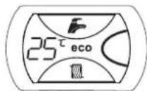
TEST mode activation
Press the heating buttons (detail 3 - fig. 1) together for 5 seconds to activate the TEST mode. The boiler lights at the maximum heating power set as described in the following section.
The heating and DHW symbols (fig.14) flash on the display; the heating power will appear alongside.

fig. 14 - TEST mode (heating power = 100%)
Press the heating buttons (details 3 and 4 - fig. = 1) to increase or decrease the power (Min. = 0%, Max. = 100%).
If the TEST mode is activated and enough hot water is drawn to activate the DHW mode, the boiler remains in TEST mode but the 3-way valve goes to DHW.
To deactivate the TEST mode, press the heating buttons (details 3 and 4 - fig=1) together for 5 seconds.
The TEST mode is automatically deactivated in any case after 15 minutes or on stopping of hot water drawing (if enough hot water has been drawn to activate the DHW mode).
Adjustment of pressure at the burner
Since this unit has flame modulation, there are two fixed pressure values: the minimum and maximum, which must be those given in the technical data table according to the type of gas.
Connect a suitable pressure gauge to pressure point "B" located downstream of the gas valve
- Remove the protection cap "D" undoing screw "A".
Operate the boiler in TEST mode.
-Adjust the power to the max. value.
- Adjust the max. pressure with screw "G", clockwise to increase the pressure and anticlockwise to decrease it
- Disconnect one of the two Faston connectors from the modureg "C" on the gas valve.
- Adjust the min. pressure with screw "E", clockwise to decrease the pressure and anticlockwise to increase it.
· = Reconnect the Faston connector detached from the modureg on the gas valve.
= Check that the maximum pressure has not changed.
Refit protection cap "D".
To end the TEST mode repeat the activation sequence or wait 15 minutes.

After checking or adjusting the pressure, make sure to seal the adjustment screw with paint or a specific seal.

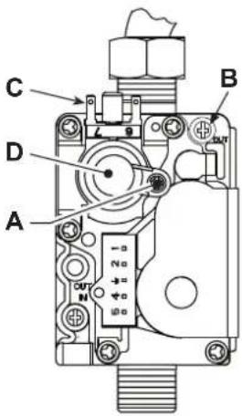
fig. 15 - Gas valve
A - Protection cap screw
B - Pressure point downstream
C - Modureg cable
D - Protection cap
E - Min. pressure adjustment
G-Max. pressure adjustment
Heating power adjustment
To adjust the heating power, switch the boiler to TEST mode (see sec. =4.1). Press the heating buttons detail 3 - fig. =1 to increase or decrease the power (min. = 00 - max. = 100). Press the reset button within 5 seconds and the max. power will remain that just set. Exit TEST mode (see sec. =4.1).
Lighting power adjustment
To adjust the lighting power, switch the boiler to TEST mode (see sec. =4.1). Press the DHW buttons (detail 1 - fig. =1) to increase or decrease the power (min. =00 - max. =60). Press the reset button within 5 seconds and the lighting power will remain that just set. Exit TEST mode (see sec. =4.1).
4.2 Startup
Before lighting the boiler
-Check the seal of the gas system.
-Check correct prefilling of the expansion tank.
Fill the water system and make sure all air contained in the boiler and the system has been vented.
= Make sure there are no water leaks in the system, DHW circuits, connections or boiler.
= Check correct connection of the electrical system and efficiency of the earthing system.
= Make sure the gas pressure for heating is that required.
= Make sure there are no flammable liquids or materials in the immediate vicinity of the boiler
Checks during operation
Switch the unit on.
= Check the tightness of the fuel circuit and water systems.
- Check the efficiency of the flue and air/fume ducts while the boiler is working.
= Make sure the water is circulating properly between the boiler and the systems.
Make sure the gas valve modulates correctly in the heating and domestic hot water production stages.
Check correct boiler lighting by performing various tests, turning it on and off with the room thermostat or remote control.
Make sure the fuel consumption indicated on the meter matches that given in the technical data table in cap. 5.
= Make sure that with no demand for heating, the burner lights correctly on opening a hot water tap. Check that in heating mode, on opening a hot water tap, the heating circulating pump stops and there is regular production of hot water.
Make sure the parameters are programmed correctly and carry out any required customisation (compensation curve, power, temperatures, etc.).
4.3 Maintenance
Periodical inspection
To ensure proper operation of the unit over time, have qualified personnel carry out a yearly inspection, providing for the following checks:
- The control and safety devices (gas valve, flow switch, thermostats, etc.) must function correctly.
The fume exhaust circuit must be perfectly efficient.
(Sealed chamber boiler: fan, pressure switch, etc. - The sealed chamber must be tight: seals, cable glands, etc.)
(Open chamber boiler: anti-backflow device, fume thermostat, etc.)
The air/fume terminal and ducts must be free of obstructions and leaks
- The burner and exchanger must be clean and free of deposits. Do not use chemical products or wire brushes to clean.
The electrode must be properly positioned and free of deposits.

fig. 16 - Electrode positioning
The gas and water systems must be tight.
The pressure of the water in the system when cold must be approx. 1 bar; otherwise, bring it to that value.
The circulating pump must not be blocked.
The expansion tank must be filled.
The gas flow and pressure must match that given in the respective tables.
4.4 Troubleshooting
Diagnostics
The boiler is equipped with an advanced self-diagnosis system. In case of a boiler fault, the display will flash together with the fault symbol (detail 11 - fig. 1) indicating the fault code.
There are faults that cause permanent shutdown (marked with the letter "A"): to restore operation, press the RESET button (detail 6 - fig. 1) for 1 second or RESET on the optional remote timer control if installed; if the boiler fails to start, it is necessary to eliminate the fault.
Faults marked with the letter "F" cause temporary shutdowns that are automatically reset as soon as the value returns within the boiler's normal working range.
Table of faults
Table. 8 - List of faults
| Fault code | Faults Possible cause Cure | ||
| A01 | No burner ignition | No gas | Check the regular gas flow to the boiler and that the air has been eliminated from the pipes |
| Ignition/detection electrode fault | Check the wiring of the electrode and that it is correctly positioned and free of any deposits | ||
| Faulty gas valve | Check the gas valve and replace it if necessary | ||
| Ignition power too low Adjust the ignition power | |||
| Excessive condensate level | Empty / clean the trap | ||
| A02 | Flame present signal with burner off | Electrode fault | Check the ionisation electrode wiring |
| Card fault Check the card | |||
| A03 | Overtemperature protection intervention | Heating sensor damaged | Check the correct positioning and operation of the heating sensor |
| No water circulation in the system | Check the circulating pump | ||
| Air in the system Vent the system | |||
| Safety thermostat interven- tion | Check safety thermostat operation | ||
| F04 | Card parameter fault | Wrong card parameter setting | Check the card parameter and modify it if necessary |
| Fault code | Faults | Possible cause Cure | |
| F05 | Air pressure switch (fails to close contacts within 20 sec. of fan activation) | Air pressure switch contact open | Check the pressure switch / Fan / Fan socket |
| Faulty air pressure switch wiring | Check the wiring | ||
| Wrong baffle Make sure the baffle is correct | |||
| Flue obstructed or not correctly sized | Check the length of the flues / Clean the flues | ||
| Air pressure switch (fails to close contacts within 20 sec. of fan activation) due to activation of the fume thermostat | Exchangers dirty (clogged on water side) | Clean the exchangers | |
| Faulty water circulation | |||
| A06 | No flame after the ignition phase | Low pressure in the gas system | Check the gas pressure |
| Burner minimum pressure setting | Check the gas pressures | ||
| F07 | Air pressure switch (contacts closed on activation of fan) | Air pressure switch contact open | Check the pressure switch / Fan / Fan socket |
| Faulty air pressure switch wiring | Check the wiring | ||
| Wrong baffle Make sure the baffle is correct | |||
| Flue obstructed or not correctly sized | Check the length of the flues / Clean the flues | ||
| A09 | Gas valve fault | Wiring disconnected Check the wiring | |
| Faulty gas valve | Check the gas valve and replace it if necessary | ||
| F10 | Delivery sensor fault | Sensor damaged | Check the wiring or replace the sensor |
| Wiring shorted | |||
| Wiring disconnected | |||
| F11 | DHW sensor fault | Sensor damaged | Check the wiring or replace the sensor |
| Wiring shorted | |||
| Wiring disconnected | |||
| A15 | Air pressure switch (fails to close contacts within 20 sec. of fan activation) | Fault F05 generated 5 times in the last 24 hours | See fault F05 |
| A16 | Gas valve fault | Wiring disconnected Check the wiring | |
| Faulty gas valve | Check the gas valve and replace it if necessary | ||
| A23 | Card parameter fault | Wrong card parameter setting | Check the card parameter and modify it if necessary |
| A24 | Card parameter fault | Wrong card parameter setting | Check the card parameter and modify it if necessary |
| F34 | Supply voltage under 140VAC | Electric mains trouble | Check the electrical system |
| F35 | Faulty mains frequency | Electric mains trouble | Check the electrical system |
| F37 | Incorrect system water pressure | Pressure too low | Fill the system |
| Water pressure switch damaged or not connected | Check the sensor | ||
| F43 | Exchanger protection intervention | No system H2O circulation | Check the circulating pump |
| Air in the system | Vent the system | ||
| F50 | Controller DBM32 fault | Controller DBM32 internal error | Check the earth connection and replace the controller if necessary. |
| F51 | Controller DBM32 fault | Controller DBM32 internal error | Check the earth connection and replace the controller if necessary. |
5. TECHNICAL DATA AND CHARACTERISTICS
Table. 9 - Key fig. 19, fig. 21, fig. 22 and fig. 23
| 5 | Sealed chamber | 37 | Cold water inlet filter |
| 7 | Gas inlet Ø 1/2" | 38 | Flow switch |
| 8 | Domestic hot water outlet Ø 1/2" | 39 | Water flow limiter |
| 9 | Cold water inlet Ø 1/2" | 40 | DHW temperature sensor |
| 10 | System delivery Ø 3/4" | 41 | Air pressure switch |
| 11 | System return Ø 3/4" | 42 | Gas valve |
| 14 | Safety valve | 43 | Air pressure switch |
| 16 | Fan | 44 | Gas valve |
| 19 | Combustion chamber | 45 | Expansion tank |
| 22 | Bumer | 46 | System filling cock |
| 27 | Copper exchanger for heating and hot water | 47 | Ignition and detection electrode |
| 28 | Fume manifold | 48 | Divertor valve |
| 29 | Fume outlet manifold | 49 | Water pressure switch |
| 32 | Heating circulating pump | 50 | Fume baffle |
| 34 | Heating temperature sensor | 51 | DHW exchanger |
| 36 | Automatic air vent | 52 | Automatic bypass |
| 53 | Condensate union |
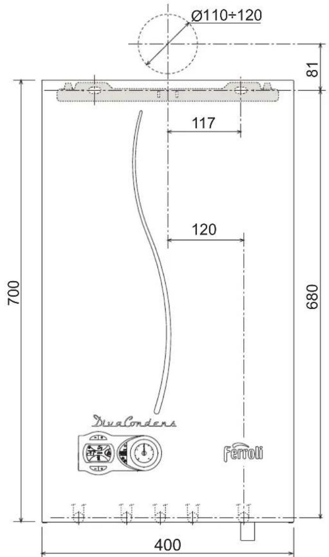
5.1 Dimensions and connections
fig.17-Front view
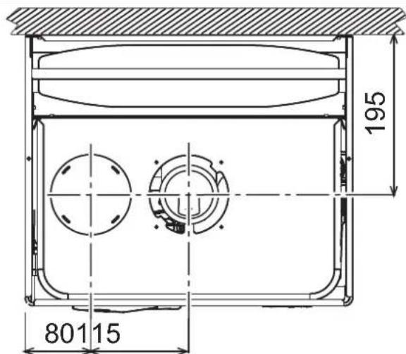
fig.18 - Top view
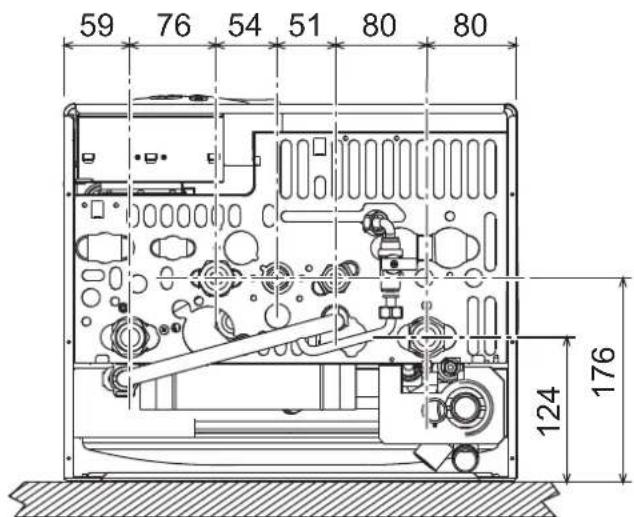
fig. 19 - Bottom view
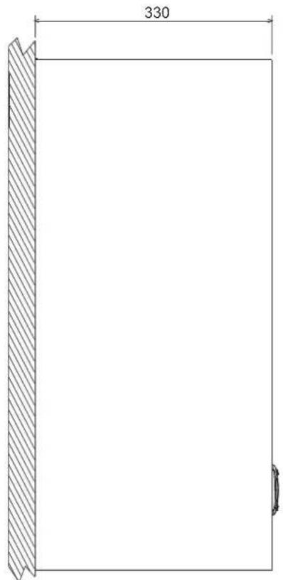
fig.20-Side view
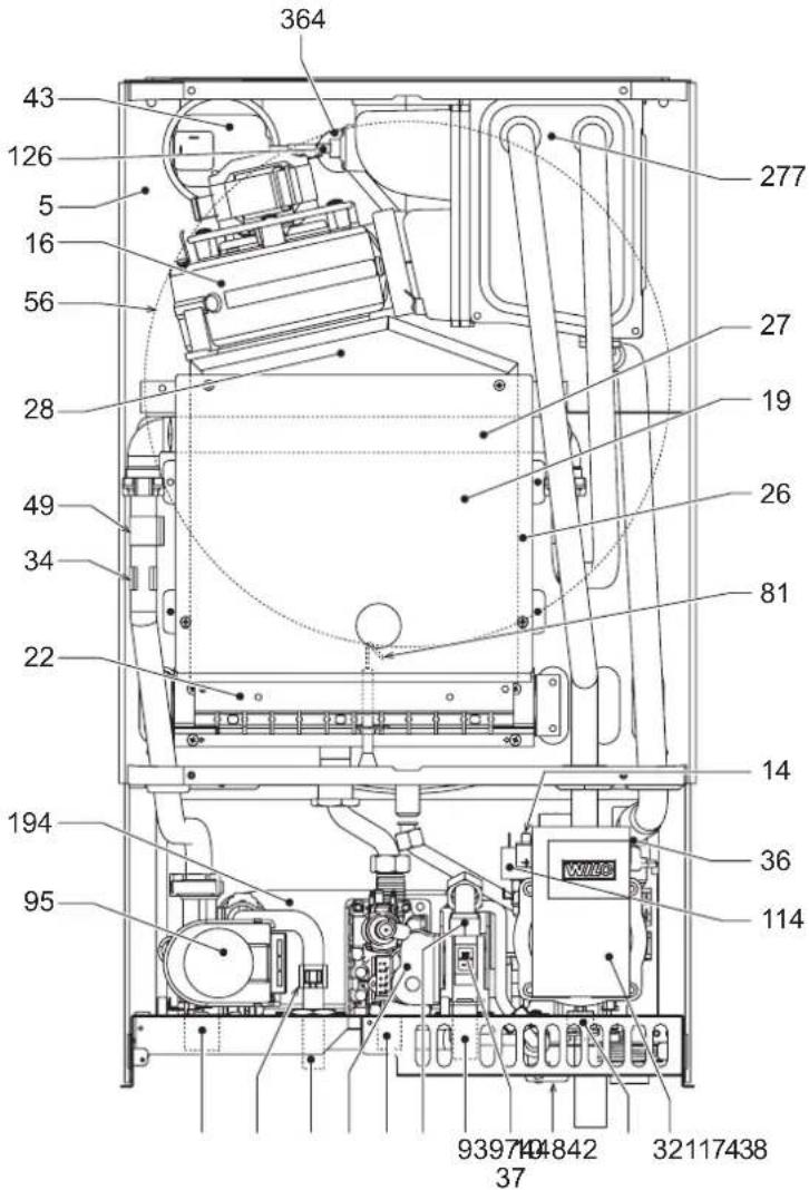
5.2 General view and main components
fig.21 - General view

5.3 Hydraulic circuit
fig.22- Heating circuit
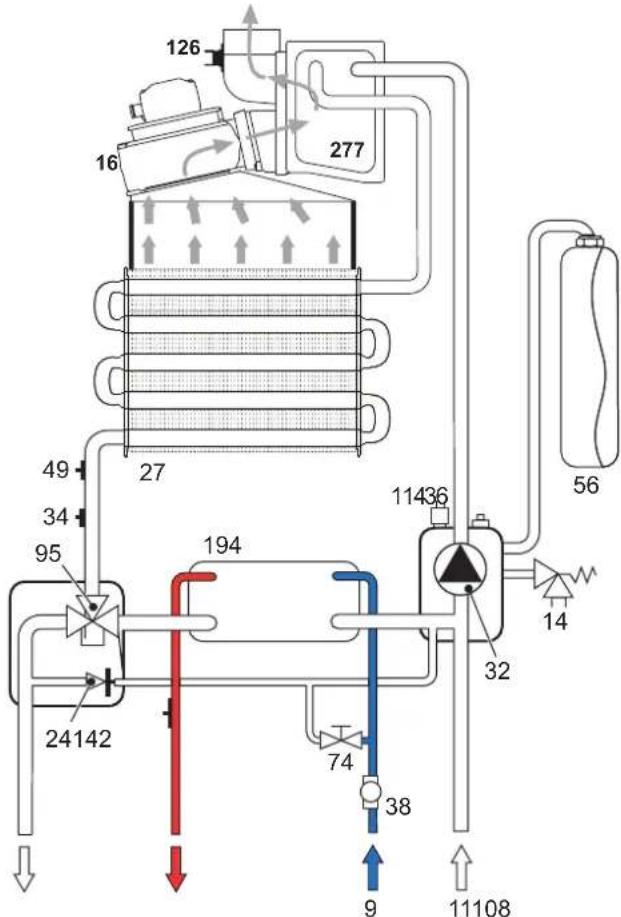
fig.23-DHW circuit
5.4 Technical Data Table 5.5 Diagrams
| Date Unit DIAcondens F24 DIAcondens F28 | ||||
| Max. heating capacity kW 25.0 28.0 (Q) | ||||
| Min. heating capacity kW 10.0 10.0 (Q) | ||||
| Max. Heat Output in heating (80/60°C) kW 24.1 | 27 | (P) | ||
| Min. Heat Output in heating (80/60°C) | kW | 9.2 | 9.2 | (P) |
| Max. Heat Output in heating (50/30°C) kW 25.9 | 29 | |||
| Min. Heat Output in heating (50/30°C) | kW | 9.6 | 9.6 | |
| Efficiency Pmax (80-60°C) | % | 96.5 96.5 | ||
| Efficiency Pmin (80-60°C) | % | 92.0 92.0 | ||
| Efficiency Pmax (50-30°C) | % | 103.5 | 103.5 | |
| Efficiency Pmin (50-30°C) | % | 96.0 | 96.0 | |
| Efficiency 30% | % | 101.6 | 101.6 | |
| Burner nozzles G20 | no. x ∅ | 11 x 1.35 | 11 x 1.35 | |
| Gas feed pressure G20 | mbar | 20 | 20 | |
| Max. pressure at burner G20 | mbar | 11 | 13.5 | |
| Min. pressure at burner G20 | mbar | 2 | 2 | |
| Max. gas flow G20 | \( m^3/h \) | 2.65 | 2.96 | |
| Min. gas flow G20 | \( m^3/h \) | 1.06 1.06 | ||
| Burner nozzles G31 | no. x ∅ | 11 x 0.82 | 11 x 0.82 | |
| Gas feed pressure G31 | mbar | 37 | 37 | |
| Max. pressure at burner G31 | mbar | 29 | 35 | |
| Min. pressure at burner G31 | mbar | 5 | 5 | |
| Max. gas flow G31 | kg/h | 1.94 | 2.18 | |
| Portata gas min G31 kg/h 0.78 0.78 | ||||
| Efficiency class Directive 92/42 EEC | - | ★★★★★ | ||
| NOx emissions class | - | 3 | 3 | (NOx) |
| Max. working pressure in heating | bar | 3 | 3 | (PMS) |
| Min. working pressure in heating | bar | 0.8 | 0.8 | |
| Max. heating temperature | °C | 90 | 90 | (tmax) |
| Heating water content | litres | 1.5 | 1.5 | |
| Heating expansion tank capacity | litres | 8 | 8 | |
| Heating expansion tank prefilling pressure | bar | 1 | 1 | |
| Max. working pressure in DHW | bar | 9 | 9 | (PMW) |
| Min. working pressure in DHW | bar | 0.3 | 0.3 | |
| DHW flow rate Dt 25°C | l/min | 13.9 | 15.6 | |
| DHW flow rate Dt 30°C | l/min | 11.6 | 13.0 | |
| Protection rating | IP | X5D X5D | ||
| Power supply voltage | V/Hz | 230V/50Hz | 230V/50Hz | |
| Electrical power input | W | 99 | 123 | |
| Empty weight | kg | 35 | 35 | |
| Type of unit | \( C_{12}-C_{22}-C_{32}-C_{42}-C_{52}-C_{62}-C_{72}-C_{82} \)\( B_{22}-B_{32} \) | |||
| PIN CE | 0461CP1030 | |||
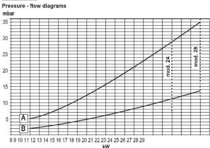
A = LPG - B = NATURAL GAS Circulating pump head / pressure losses

A = Boiler pressure losses - B = Circulating pump speed
rprodufhe
24
| brdembrk:### | |||
| brdembrk:### | |||
| brdembrk:### | |||
| brdembrk:### | |||
| brdembrk:### | |||
| brdembrk:### | |||
| brdembrk:### | |||
| brdembrk:### | |||
| brdembrk:### | |||
| brdambrk:### | |||
| brdembrk:### | |||
| brdembrk:### | |||
| brdembrk:### | |||
| brdembrk:### | |||
| brdembrk:### | |||
| brdembrk:### | |||
| brdembrk:### | |||
| brdembrk:### | brdembrk:### | brdembrk:### | brdembrk:### |
| brdembrk:### | brdembrk:### | brdembrk:### | brdembrk:### |
| brdembrk:### | brdembrk:### | brdembrk:### | brdembrk:### |
| brdembrk:### | brdembrk:### | brdembrk:### | brdembrk:### |
| brdembrk:### | |||
| brdembrk:### | |||
| brdembrk:### | |||
| brdembrk:### | |||
| brdembrk:### | |||
| brdembrk:### | |||
| brdembrk:### | |||
| brdembrk:### | |||
| brdembrk:### | |||
| BRD | brdembrk:### | brdembrk:### | brdembrk:### |
| BRD | brdembrk:### | brdembrk:### | brdembrk:### |
| BRD | brdembrk:### | brdembrk:### | brdembrk:### |
| BRD | brdembrk:### | brdembrk:### | brdembrk:### |
| BRD | brdembrk:### | brdembrk:### | brdB |
| BRD | brdembrk:### | brdembrk:### | brdB |
| BRD | brdembrk:### | brdembrk:### | brdB |
| BRD | brdembrk:### | brdembrk:### | brdB |
| BRD | brdembrk:### | brdembrk:### | brdB |
| BRD | brdembrk: ### | brdB | 19 |
()原-10p#nurtdr# 60°reunr#p#r#r#r#r#r#r#80°
(1)2w0p3nur 10s2e0000000000000000000000000000000000000000000000000000000000000
rprodufhe
28
| br#dem#rk:### | ||||
| ### | ||||
| ### | ||||
| ### | ||||
| ### | ||||
| ### | ||||
| ### | ||||
| ### | ||||
| ### | ||||
| ### | ||||
| ### | ||||
| ### | ||||
| ### | ||||
| ### | ||||
| ### | ||||
| ### | ### | ### | ### | |
| ### | ### | ### | ### | |
| ### | ### | ### | ### | |
| ### | ### | ### | ### | |
| ### | ### | ### | ### | |
| ### | ### | ### | ### | |
| ### | ### | ### | ### | |
| ### | ### | ### | ### | |
| ### | ### | ### | ### | |
| ### | ### | ### | ### | |
| ### | ### | ### | ### ### | |
| ### | ### | ### | ### | |
| ### | ### | ### | ### | |
| ### | ### | ### | ### | |
| ### | ### | ### | ### | |
| ### | ### | ### | ### | |
| ### | ### | ### | ### | |
| ### | ### | ### | ### | |
| ### | ### | ### | ### | |
| ### | ### | ### | ### | |
| ### | ### | ### | ||
| ### | ### | ### | ||
| ### | ### | ### | ||
| ### | ### | ### | ||
| ### | ### | ### | ||
| ### | ### | ### | ||
| ### | ### | ### | ||
| ### | ### | ### | ||
| ### | ### | ### | ||
| ### | ### | ### | ||
| ### | ### | ### | ||
| ### | ### | ### | ||
| ### | ### | ### | ||
| ### | ### | ### | ||
| ### | ### | ### | ||
| ### | ### | ### | ||
| ### | ### | ### | ||
| ### | ### | ### | ||
| ### | ### | ### | ||
| ### | ### | ### | ||
| ### | ### | ### | ||
| ### | ### | ### | ### | |
| ### | ### | ### | 20 | |
()原-10p#nurtdr# 60°recunrpu#r#r#r#r#r#80°
(1)W-turw-pnrur 102srrnrs30°B,dtw-turpnrur318rs37°B,drur50°rur50tur
5.6 Wiring diagram

fig. 24 - Wiring diagram

Attention: Remove the jumper on the terminal block before connecting the room thermostat or remote timer control.
16 Fan
32 Heating circulating pump
34 C.H. flow temperature sensor
38 Flowswitch
42 DHW temperature sensor
43 Air pressure switch
44 Gas valve
47 Modureg
49 Overheat cut-off thermoslat
72 Room thermostat (not fitted)
81 Ignition and detection electrode
95 Diverting valve
114 Water pressure switch
126 Contact fume thermostat
139 Remote timer control (not fitted)
193 Trap
FR
1. DISPOSITIONS GENÉRALES
Selection Eco/Comfort
Haxmte KhoKy BKn/BbKn (no3.7-pnc.1)B TeueHe 5 ckyHd
pnc.2-BbiknoueHneKOTna
Korda KOten BbIKHOaETcra, 3NEKTPNeCKoe NITAHHe BCE eue NoCTyNaet Ha 3NtPOHNYI npHTy. He paOToAOT CNCTEMA TBC nOTOnNEHHo. OCTaTeCAkTNBOH CNTEMA pONTIB ONeHEHn. YTO6b CHOBA BKNIOHTB KOtEN, HAKMITE NOBTOPHo HA KONKO BYK/ByIK (no3.7 PNC.1) B TeHeHne S cekHyd.
pnc.3
3TMM ObecneHbAeCTa HEMeNHeHAR TOBHOCTb KOtaOte KaJdbIpa3 npn NotpehEnm RopHe BODb INN pNp 3anPoce Ha OTOnHeMe (Bb3bAeMbIM KOMaTHbIM TepMOCTATOM ININ DNTAHUONHbIM TepMOCTATOM C TaIImePOM).

PnO tKIOUHcHm KOTn oT cNCTeMbI 3NEKTPoNTaHn H/INn Ra30BOB MARITCPaHn FyHKnIPOTN B ONEDEHHeH NKTIOVAETcB. BO BpEma DINTIEbHO HEMCNLOB3OBAHn KOTNa B 3MIMN NEPMOD, BO n6ExaHHe YUepeBa OT Bo3MOKHO TzAMep3AHn PEKOMEHdyTeC CNTb BCIO BOYu nKOTNa, kAK IN KOHTypA TBC; IJN Jx e CNTb ToNko BOY u KOTypa TBC uO6abUT bANTFPnB B CNTcEMy OTONneHn, B COOTBeCTBm C yka3AHmM, pnpBeDeHHBMn B SEZ.3.3
2.4 PervynipOBKu
IpeeknHueHne pexmOB "JTeo"/"3Ma"
HaxMMTe KhoNkY "IeTo"/"3nMa"(no3.6-pnc.1)Ha 2 cekyHdbi.
Ha dncnnee BbcBntucr CmBON "Neto" (no3. 10 - pnc. 1): Pnp 3tOM KOten 6ydet Bbpaabibatb TOnbKO BOy DnA TBC. Octaetc AKTNBHO CNTema aHTN3aMeP3AHNA.
Дя Вькюуну рекима "ПeTo" BHOБь HαхмITE KнОКу "ЛeTo"/"3nma" (no3.6 - pUC.1)Ha 2 cekyHdI
PerynpobkA TeMnepaTpybI BOdbI B CnCTeMe OToJIeHn
C NOMOJIbKHOHONOK CNTEMbI OTONNEHnA (No3.3u4-pnc.1) TEmpePaTyP MoXHo peYIMPOBaTbOT MHNHMaNbHOH 30°C Do MAKcHMaNbHOH 80°C.

pnc.4
PerynpobKa tempepatbI B cnteMe ropyeoBoDocha6xhenra (TBC)
C NOMOJIbIO KHOIOK CnCTeMbI TBC (no3.1 n 2 - pnc.1) TEMNepaTyPOMOHOPeryNIOBAtb OT MHHMAnbHO40°C Do MAKcMAmbHO55°C.
pnc.5
PerynpobKa TemnepaTpyb Bo3dya B NOMeHNN (C NOMOuBIO ONUHOHHOR TepmoCTATA TEMpePApyb B NOMeHNN)
3aaiTe C NOMOsbTO TepMoCTaTATEmpaTpybBOzdyxaB NOMEeHnHyxHyTO TEmnpatpy BHTpynomeueHHN. PpN OTCyTcTBNN TepmoCTATA TmepaTpyb BOzdyxa B NOMEeHHN KOTEN ObecneYBaET NOdEprKaHHe B CNTeMe OTOnnEHn 3aDaHHo TEmnpatpy BoDly.
PerynnpOBKa Temnepatypb BO3dyxa B nomeeHNN (C nOmoBIO onuOHHO yctpoiCTBa Dc TaHMePOM)
3aaiTe C NOMOJIbO yCTPOINCTBa DY C TAIpeMOp HxHHyo TEMNepaTyP BHTPN NOMeHIna. KToEN 6yET NOdEpxKINbT B TMEpAtpy BOIb B CNTMe, HE05XODmYIO DnB OepeHEnaB NOMeHInaHHO TMEnpAtpy Bo3Dyxa. B TOM, CTOKACAETcra pAObTI KAOTa c YCTPOINCTBOM DY C TAImePOM, CM COOTBECTByUOuY INCHPTyKUMO HA 3TO yCTPOINCTBO.
Bb60ppeKMOB ECO/COMFORT
KoTeIobopyoBaan CneuaHbNoi OyHKuue, ObecneuBaOue BbICOKyo CKOpocTb NOaHBOBt B CNTeME IBC N MaKcImaHbHbN KOMpOPT dNnONb3OBaTeN. Korda 30 yCTPOINCTBO3AedCTBOaHO (peXIM COMFORT), OHO NOdepKHaET TEMnepatypy HaxoJauEeB KOTNe BOBt, ObecneuBaT Ecm CambH HeMeDnHHeo NoctynnHee ropae BoBn pOn OTkpbITn KpaHa N YcTaPraHr Heo6xOIdMOCTb XDaTb 3TOrO HEKOTOPoe Bpem.
DaHHeO yctpoIcTBO MOKet 6bIb OTKnIOUeHO NOIb3OBaTeIem (peXHM ECO), Haxkab KnaBnIyEco/comfort (no3.7 - pnc.1).PmP pa60te B peXMME ECO HA cnsnee BBcIEBBAeTc COOTBeTCTByKOUI CNBOMN (no3.12 - pnc.1).DJIa BKIOUeHry peXUMA "KOMΦOPT"CHOBa HxMITE KOHNQ "3KoHOMuHbI"KOMΦopt" (no3.7 - pnc.1).
PerynpoBaHne c dntaHnOHHO npbTa ynpabHeHc TaMepor
Ecn K OTN N OKnKIOHcOeYcTO PocTBO DnCTaHcHOnHO TnpaBHeHc TaIIMepoM (OuH) BbIeONCAHHbE peryiINpOBkpnON3BOrTaB COOTBETCBN C Yka3AHHMm, PNBEDEHHBMn BA7Jlnca 1.
Ta6nua.1
| Peyunipobka temepatrybdo b v cncteme otponenhy | Peyunipobky mojno ocyuieactanty kak chepez meho Tynba D y c TaHmepom, tak i C naehi npaBnHnien KOTna. |
| Peyunipobka temepatryb b cncteme ropanefo bocchabokhenia (TBC) | Peyunipobky mojno ocyuieactanty kak chepez meho Tynba D y c TaHmepom, tak i C naehi npaBnHnien KOTna. |
| Ipekenuoyenne pekHMOB "JeTo"/ "3nma" | PekHM "JeTo" obndaet prkopmtetrom Hnd KOMaHdN ha Bklnouyenne otponenhy, KOTpora MOKet noctynntb ot npbTa D y c TaHmepom. |
| Bb6op pekmohm "3KOHOMHHy" "/ "KOMΦOPT" | Bb6op XbaAemoro pekmahm okaet ocyuiectbnrta Ctonbko c naehi npaBnHnien KOTna. |
Perynpobka daBneHn BODbI CnCTeMe
DabneHHe Hanopa np3aONHeHH XOJOnHO KOHTypa, CunTaHHe rnpometpOM KOTHa (no3.17 - pmc.1), DOJIHKoCCTABnTb np6nHnENTbHo 1,06ap. EcnBo BPemr paBotsI daJIbeHHe BObl B CISTepe ynaTeD To BeMNHN HIXKe MNHMAnbHO dOnyctmHoi, KOTen 6byET OCTaHOBJEH N Ha DCtNCEE BbCeBTTCs OUnbKa F37. CNOMOuBO Kpana DnA 3aNNBKn BObl (no3.1 Pmc.6) DoBeCTNs daJIbeHHe do nepBOHaauhBO HorO 3aueHn. No OKOHaHHn Oepaunn BCerda 3akpbBaIne KpaH 3aNNBKn BObl.
Pnc.6-Kpaan 3aonHHeHHKoTna
- MOHTAX
3.1 Yukazamaо obseero xaapaktepa
YCTAHOBKA H ACTPOKIA TOPEKNI DOJNKHA OCUJECTBJIATbCR TOLbKO CNEUAMIN3HPOBAHNbIM NEPCOHANIOM IMEIOUIM NPOBEPEHNVIO KBALNFOKALNIO, PNI COBLODEHMN IPNBEDEHbIX B HACTOJEM TEXHNUECKOM PYKOBODCTBE YKA3AHIN, PNEIINCAHIN DECTBYIOUE 3AKOHODATEJBCTBA, NOJOKEHN MECTHBIX HOPM INPABIN, IN COOTBETCTBNI CPNHRTbIMN TEXHNUECKIMTNPEBOAHNRMI.
3.2 MecTo yCTaHOBKM
Kamepa cropahna arperata repmetnHIO hOJINPOBAHa OTHOCITeBHO NOMEUHNA NO3OTMY OH MOXET INOIb3OBaTcB B JIO6OM NOMEUHNN. TEM He MeHee NOMEUHNE, B KOTOPM YCTAHANBaTEcR KOTeN, DIOJNXIO IMeTb DOCTAOHY BOHTNIAUO DnA npEDOTBPAEHN ONaCHbC uTyauN C BuCyae XOTb 6bl MaNbEyYteK ra3a. 3Ta HopMa 6e3oNaChOCTN npEDCMTOpe HINpKTIBNOCEE No 2009/142 nnBCEx pa6Otaouix Ha r3e arperatOB, B TOM UNCNE IN DnTAK HA3bIaEBMx arperatoB C 3akpbToN KAMEPOI.
Annapat MoXeT pAbToB b YAcTHHIO 3auHHeHOM MeCTe, cOrNaCHO CTaHapTy EN 297 pr A6, npi TemnepaType-5C. PeKMeHdyTec yTaHOBHTb KOteN pOd cKaTOM KpbIu, BHyTpB 6anKoHa Hnn 3auHHeHoi HnHi.
B IIO6OM CNYuae, B MecTe yCTaHOBKn He DoJIKNHb HAXOINTBcR Nblb, OrHeONaChIe npEIMTeblnMATEpMaIbnbln eKne r3bl.
Koten npedha3HaueH dno nOBeckn Ha CTehy n NOCTabnEeTcB KOMNNEKe C noDBeCHbHM KPOHHTeHOM. PnpkpenITE KPOHHTeH K cTeHE B COOTBETCBMN c pa3MePAMn, npBedeHNBMn B pnc. 17, nNOBecbte H a Hero Koten KpennHe M cTeHe dONxoHObecneuBaTb CTaBnBOCTb NPOHOCTb NPOJOxEHN KOTNA.

Ecni arperat yctahabnmbaetc cpei Me6eHN HIN 50KOM KCTHE, CneDyET npdycmptb CbooHoe IpocTpaTHCtO, Heo6xOJIMoe DnA demOHTaKa KOKXy H BnIOJIHeHNE OBHyhX paB0T no TEO6CNYKBAHINO.
3.3InpaBnueckne coeHHeHna
PpeDynpeKdEHHa
CnBHOe OTBepCTne npedoxpanHTbHoro KNanana DOJINHO 6bIb CoeHHeo CBOPOHKN IIN CO CNBHO Tpybo BO N36BXAHNE HANHNA BOI HA NOB CNYae NOBbEHNH DAJIENHRA BOTONNTbHOM KOHTYPE. B nOPTBNHOM CUYae N3TOBOTEnb KOTNa HE HeCET HAKKOt OBETCTBEHHOCTHa 3aTOnnHEH NOMEUHNN PnPcpaBtBaHnnnpDexpAnHTenHoro KNANA
Ipeed BInIOHHeHM NOKINCHEN CHNEyET NPOBEPHTb, Yo annapat rTOB dny paOtoBc HmEOUUMC M TINOM rasa, noCe Yero BInONHHTb TuaTeBHyOH ONUCTKY BCEx TpyOBpOBoD OTONHTbeHbONCTeMbI.
BbINOHNHTe NOkKnIOUeHnK COOTBetCTByOuCmM WTyuepam corlacho YeTeKxHa pnc.19 IN B COOTBetCTBN C CNMBONAMN, IMEKOUMNCs Ha cAmOM arperate.
PnmuueHne: arperat Ochaen BHytpHHIM 6aINaChbIM KlaanahOM B CNTeMe OTOpJIeHn.
XapakTeepnKu BOBdIIN CHCTeMbOTONHeH
B cnyuae, ecnn jeeKTObT BOdu npBeBlaaet 25° Fr (1°F = 10 nmm CaCO₃), HcnoIb3yemar BODa DOnJHka6 bbl TaNdeNekaaM opa3oM noDrotOBnHeA, TOb6b npedOTpauaTb Opa3OBAHne HAKIN B KOTNE.
CnCTema 3aunbIOT 3amep3aHn,KnKne aHTnΦp3bl,do6aBkn HnRn6ntOpbl
IcnoIb3oBaHHe JnKINx AHTNcPn3OB, D06aBOK IN HnHnOHTOpOB pa3pe7aTeCBA Cyueae Heo6XoIMOCNT TONKBO IN NCKIOHHTeBHO, ECNI IN 3FOTOBtNE BdAET RAPAHTMO, NOITBepKdaOnyU, YTO erpoNDyKuIN OTEBueaET DAHNOMBY DHy NCNo1b3OBAHIN He pInuHINBT BpDA TENNOOOMEHHNK KOTNA IN DpyfMM KOMNNEKTYOUMM INHm MATEpNaANAM, NCNoIb3oBaHHbIM B KOHCTPyKUn KOTNA IN CnCTEmbl. 3AnpeuaETCA NCNo1b3OBAbT XJDKHE AHTNcPm3Bb, D06BaKbIM IN HnRbNtOpBl, HE npeHa3aHuEHnle CneauNaHbNO I Na PImEHeHnB B TEINIOBbIX YCTAHOBkX IN HecOBMeCTMbIE C MATEpNaANAM, NCNoIb3oBaHHbIM B KOHCTPyKUn KOTNA IN CnCTEmbl OTONNEHnE.
3.4 RaObIe COeHNHeHn
r3 noDKHIOAETcK COOTBcTcByOuIeMy nATpy6ky (cm. pnc. 19) c co5nIOHeHem
dEChTBouHX HOpM, C nCnONb3oBAHMe JXeCTKO METaIINueCKO Tpy6bl IIN mR6KORO
WnHaRn 33 HepxABeHOUe CTAnn Co CnNOuHOI ONNeTKO.Mekdy raoNpOBOM IN
KOTJOM DOJIKeH 6bIbYcTAHOBJERAOBKn PkaH. IpOBePbTe repMetTuHOCtB CeX
ra3OBbIX COeMHENH.
3.5 3NeKTPnueckne CoeunHeHHa
PpeDynpexdHn
Annapat donJxhen 6bIb noKIOHcH K HaeXHO CnCTeMe 3aEMHeHHB, BINOHNHO B COBTBECTBUN C DeINCTBYOUIMN HopmAMn TEXHNK6eONACHOCTN.3oOFeKtIBMBOCTb KOHTpya 3aEMHeHHN Iero COOTBeTCTBNE HopmAMdoJXHHb 6bITnPOBepHeB KBALINPHIOPOBaHHM NepcoHaIOM.13rOToBNTEn He Hecet HIKAKOYOBTEBHOCHCTa yUeP6, MoryuNN 6bITb npnuHHeHHbIM OTCyTCTBmE 3aEMHeHHa annapata.
BHytpenhne 3nEeTpHecKne coeHHeNn B KOTne yKe BbINONHeHb, OH ChA6xekn TAKKE CTeBbIM WHPOM Tnna "Y" 6e3 BUNKn. POKIOHcHHe N 3nEeTpueckO CETn DOnkHO 6bTb BbINONHeO B BnDE PmKcPOBaHOrO CoeHNHeNn, OobpyoBaHOrO DByXIOIOChbIM BbIKIOuOaTeIeM C pacCToAHmEm MEXdy KOHTaTAMn He MeHee 3 MM. Ha yactke MekJy KOTJNO m I nctOuyHKOM 3nEeTpueckoro NITaTHn DOxKHe b 6bTb yCTaHOBNeHb PnABKHe npDeoxpaHntenn Ha cnny ToKa He 60nee 3 A. PnBnIOHHe H 3nEeTpuecknx CoeHNHeNn OChb BaxHo CO6IOctn NoJIaPHOCTb (PA3A: KopuHeBn npoBd / HEITPAJIb: cnHn npoBd / 3EMNJa: XeNTo-3eENbH npoBd.
I NpIb3OBaTeIIO 3anpeuaeTcA moCToTEnbHO npOn3BODnITb 3aMeHy Ka6eI IITAHN. B cnyae nobpeXeHINK Ka6eI BbIKNoHTe annapat n O6paauTecb K KBaIIKnFmPPOBaHbIM nePCOHaON M nE rO 3aMeHb.I B cnyae 3aMeHb 3NeKTPueCkOrO Ka6eI, NcIOnb3yTe NcKlNOHTeHb NO Ka6eI b TnIa "HAR H05VV-F" 3x0,75 MM2 C hapyKbIM dAmetpOM He 60nee 8 MM.
Tepmoctat KOMHATHOH TemnepaTypb(onu)

BHIMAHHE:TEPMOCTATKOMHATHOHTEMNEPATybldoJIXEHbItb VCTPOICTBOMC KOHTAKTAMNHE NOI HANPRAJEHMEM.PINIODAHAPRAXEHH230BAKNEMMbTEPMOCTATA KOMHATHOH TEMPEPATyPBIOBNEUET3A COBNOENIOJEXAAEE PEOMTY IOBPEXDEHHE 3NEKTPOHHOIIATbl.
Pn noKIOHueHH peryIaTOPOB KOMHaTHOH TemnepaTyb C NOBpeMHHO nporpAMMOY npVaBHeHH NIN TaMepa, He cNeyET 3aNBtBbATb IN Ycepe3 pa3MbkaOuIe KOHTAKbT. B 3aBcHmocCTOn Tnna YcTpoJcTBa NITAHNE DOONK NOBODNTCB HANPMyO OT cTeN INOT batapeek.
OcTyn K3eKtpuecko KJIeMMHO naHEn
CHB8OBUNKOTNMOXHO NORYHTb DOCTYN K 3NEKTPUeCKOHN KEMMMHON PAHNN. PaCnONQEHKeN KEMM DnA pa3NNUHbIX NOKNIOHEN INPNBOIDTC RAKKHe H 3NEKTPUeCKOHN CXEMe HA PNC.24.

PNC.7-DocTyKKNEMMHOH naHenn
3.6bIMOXOaB1
PpeDynpexdHn
DaHHb annapat OTHOCITcK TINy "C"T.E.K KOTnam C repMeTHHOI KAMepoI cOpaHnI npHHyDntBhoTTOI B03dyXO3aOpB IN bVIOxIDbIMOBbIX rAOB 108
npHcoeHNHrOCTc COBTBCTCEHBO KCNCTEMAM ACNHPaUM N bIMoyDAeHnI, KOTOpBIE DOHNKbY YODBNETOPBt PnPBDEHNHM HKe Tpe6OBaHmN. AHBnI annapat ceTPHnIPOBAH dIg pImHeHnCO BCEMN KOHPhrypauMn BO3dyXOBoB Ocy, YkaaAHHbIMn HA TabNHKe TECHUHcckMx DAnBHx. TEM He MeHee, BO3MOXHO, YTO npImHeHne HEKOTopBX KOHPhrypauMn ORPAHmHBAeTCR INI 3anPeMaTeC MEChTBHMn 3aOKHAM, HOPMAm INI npABnIMN. IpeJxde HmPcTynaTb K MOHTaKBy, BHMATeLbHO O3HaKOMbTECb C COOTBCTCYOuMM INpeDIncaHMRn M oEbcNeYbTe IX CTporoe Co6IoJeHne. KpOME TORO, Heo6xoDMIO Co6NDoTaB npABnIA, KACAIOueCePacONOKeHn ORONOBKOB BO3dyXOBoBOH Na CTHe IN IN KpbIe IN MNIHMAbHBx PACCTOHN OT OKOH, CTH, DpyTNX BO3dyXOBoBOH nT.D.
Jaaparmbl
IaOBcneHEnpaBnHbON pa60t bKOTna Heo6xOdMMN HcONlb3OBatb NOCTABnEMbBE B KOMnNEKe C annapatom dNaΦparmb, co6hJoua PnBeEHbE B NHexeCNeDyUOxuX Tabnucx yKa3AHH
IpeepyctahOBKOn ty6bblbIMoxOJa Heo6xOJIMO np0epeBt HaHnue HAdnEaee dAaDpaarmBc (ecnn OHa DnPKHb 6bTb NcNn30BaHa), a taKke npabInhBocTh ee yCTAHKn. Dnna3ameHb DaaparmBb (no3.1 - pnc.8) BbInonHte DeiCTBn, yka3AHHe B pnc.8.

PNC.8
PoiocoeHHeHc nOmoBIO KoakcnabHbIX Tpy6
pnc.9- pnpmepbipnncoeiHHeHc nmoOuBIO KoakcnaihBbIX Tpy6 (Bo3dyx/ = DblMOBblra3bi)
Ta6nua.2-BapnaHTbI nCnoHHeHHa
Ta6nua.4-BapnAHTbI HcNoHHeHH
Ta6nua.7-BapnaHTbI NCONHeHH
| Tin | Hаименоване |
| C2X | 3a60 prinorHHORO BOZdyaи уdaneHne DBMOBbIX razOB chepez obuizn DBIMOXoJ. |
| C4X | 3a60 prinorHHORO BOZdyaи уdaneHne DBMOBbIX razOB chepez OTdJIbHbIe obuizn DBIMOXoJ, Ho ПОДЕРRAUQUHCS OduHAKOBIM BetePBOIM BOZdEHTBIM. |
| C8X | YdaneHne DBMOBbIX razOB chepez OTdJIbHbIe kINObuizn DOmIOXoJ, 3a60 prinorHHORO BOZdya Xepez OTBepCTHe B CTNIE. |
| B3X | 3a60 prinorHHORO BOZdyaи n3 NOMESEHnY yCTaHOBKn Atnapata chepez KoakCMaJIbHbIy TpybONpOBoD, (BKNIOHcHOnN DlMOOTBOJDAUYU TpyBu) u YdaneHne DBMOBbIX razOB chepez obuizn DBIMOXoJ c ECTCTBEHNHO TReOJ. |
| A BHIMAHINE - B POMEUZHIM IDOJIXHA BbITb IPEDYCMOTPEHA 3ФФEKTHIBHA CNTHEMA BEHTUNIPLIIM |
I03TOMy,ecn Bby xotne noCoeHNHb KOten DIVAcondens F24/F28 K KOJIENKTHBOMY DbIMOXOyI INN K OTDeNBHOmy DbIMOXOyC eCTeTBHHoTARIO, HEo6XODHMbIM yCIOBHeM ABnEETcA, TTObI 3TN DbIMOXObl 6BIn CNpOeKTHPOBAHbI KBaINCHPOBAHbIMn CNEUANCTAMN B COOTBETCTBN C DeNTByOUMM HopMaMm N NOxODHMn dIarperaTOB C 3aKpbITOn KaMepOn CropaHn, O6OpyDobAHbIX BEHTUNrTOPOM.
4. YXOD IN TEXHnECKOE OBCJNYKINBAHME
4.1 Perynnopobkn
IpehaTpoKaHa npyro Tnra3a
Arperat paccHTAH npaBt b KaK Ha metaHe, TaK Ha cKHeHOM HeTbHOM r3e. IIOrTOBkA KOTJIa KpOBe THa TmN DpyTOM R3a0BOM TOnnBbe PnONBODITc H 3aBOe, PnINHE COOTBETCYIooee Yka3aHme npBedeHO YAynkoBE, A taKHe TA TabNIuKe TEXNHMeCKIX DAHNbY, yCTaHOBNEHO HA CAMOM arpeBa. B Cnyueae Heo6xOIMOCTH nepeBoDA KOtHa N paBOyC r3aOM, OTNHybM OT r3aa, dNRA KOTOPo RO OH 6bl NaHactpoEH H 3aBOe, Heo6XdIMO npHObPcNTcneUaIIHO npedycMTopeHHbI dN 3ToH CEHN KOMPiNeKT dNrapeOBOpDoyBaHNA N DEiCTBOBATb, KAK YK3aHO HNKHe:
1.OTKIOUHTNE3NEKTPMHeCKOE HNTAHNEOTKOTNAH3AKPOITeTa3OBBBEHTINb
2. 3aMeHHTe fOpcyHKn Ha rnaBHOr ropEnke, ycTaHabINBaBf opCyHKn, peKoMeHDoBAHbHe B TaJIiue C TexHnueckmM DaHHbIMn HA cap.5,B 3aBNCMnOCTNOT NcONb3yEmoTnHa ra3a
3. Podaite nHTAHNE h KOETN o NTOKPORE RAOBOB BEHTINB. 4. NImeHemene napametpa, COOTBCTBkyoUero TYNU rasa?
yCTaHOBNTe KOTEn BpeKm OxuHaHn
HAKMTNE H KONHIN CNTEMBI TBC (no3.1 n 2 - pnc.1 ha 10 cekyhd:Ha dcnneB BBOBDTCA"B01 M BMTAOUOC COCTOHMA.
HAKMITE HA KHONKIN CNTeMbI TBC (no3.1 n2-pnc.1, 706bl 3a4ab npapametp 00 (Dnpa6oBt bHa metahe) nn01 (nna pa6ObTa hCaKXKeHHOM HeTnHOM rae GPL).
HAXMNTE HAKONKNCCTEMbI FBC (no3.1 u 2 -puc.1) B TeueHne 10 cekyHd.
KOTENBEPHETCBPEKIMOKNDAHNA
- Otperynnpyte MNHIMAbHo H MAKCMMaHoe DaBHeHHe Ha ropeKe (cm COOTBCTBTOU nparapap),3aDaBa 3HaENHn H3 TaBnCuIbTexHmecKnx DAnHHxDn INONBlyEYMORO TINaRa3a
- Hakneite 3TKeKky, coepkaayoc B KOMnKeTne no nepeBODy Ha pyro TIN Ra3a, BO3ne Ta5nK C TeXHnueckm DAnHHbIMY, YTO6bI NOITBepNTb COCTOBuMnCe peBOD.
AKTINBAUN TECTOBOROPexnma TEST
OHOBpEMHNO HAXMNTHE KAONKCNCTEMBI OTONNEHM (no3. 3 - pnc. 1) HA 5 ckyHy, OTOb6 BKNHOHTB TECTOBH KEXUM TEST. KOten BKNHOHTC HAMKCMALBOH MOUHOCTN, 3aADHOH TAK, KAK YKA3AHO B CNEyKOEM NaparpaPe.
Ha dncnnee Mrraiot CmBOnbl otOnnnenHn I BC (pnc. 14); pROM oTo6paXaetcMouHOCbT OToNNHeHn.

PNC.14-PexKIM TEST (MOUHOCb CnCTeMbI OTONNEHNA = 100%
HaKMMte Ha KHONK CINCTeMbI OTONNEHnna (no3. 3 n 4 - pnc. 1) dnnyBENHnna HnnyEMbSeHHN MOUHOCTHn (MHNHMaJIbHa MOnHOCt b = 00% - MaKCMMaJIbHa MOnHOCt b = 100%).
B cnyae aktnbaunm pexma TEST n 3abopa bodblg TBC,doctatoyHoro dna kntbuae npexma TBC, KOteJ octaetcB pexme TEST, H0 3-xoobon knanah nepeknoaetcB pekm TBC.
IpyOTKIOHcHINPEXIMATESTOHOBpEmHoHaKMITEHaKHONKnOTONJIeHHN(no3.3 4-puc.1)BTeyHeHNE5ckyHd.
Pekm TEST B nio6om cnuyae ABOTAMuueckn OTKIOUHTcpe3 15 MMHT no 3abepehen 3a6opa BObl TBC (B cnuyae eCN BENHUNHa 3a6opa DoCTaTOHnA dna AKTNauin peXkma IBC).
Perynpobka daBneHnHa ropeIky
3T0T aperat, OHcAunicnK TnTH C MoDyNpyEmbIM nNameHEM, IMeET DBA fKnCPOBaAHBbX 3aHcEHHa DABeHHa MHMNAbMbHO MAKCMAbHbOE. 3TN 3aHcEHHa CneDeYet 3BHTb Nt ABmHbTe XHNHeCKNX DAHNbIX HAOCHBE NcONbYEMyrO TnHa r3a.
IodknIOHTeMaHometpKpa3bemydnaZamepa daBneHn“B”,pacnoIOKeHHOMy Ha BixOde n3 ra3oBOrO knanaHa.
CHIMMTE3aHTbIKoJINaOHOK“D”,OTKpyTINBBNHT“A”.
3anyctnte koteB TectOBom pexkme TEST.
- OtperynpyTe MaKcMaJIbHyIO MOnHocTb Ha MaKcMaJIbHOe 3HaueHHe.
- Otperynpyte MaksimmaHoe Dabene Hne BuHTOM "G", nobopauwbaer ero no yacoboi cTePkn dny yBeneHHn npOTB uCaboN CTpeKN - nny yMeHBseHHa daBHeHH.
- OTOcoeHNHTOE ODNH N3 DBXV coeONHTENeON kATyUKN peYrNUPOBAHIN Modureg "C" Ha razOBOM KNAHAE.
Otperynpy MHHMnBHOE daBHeHNE BHTOM "E", nobopauBaER eo no caboBcTpeKN drr yBEnueHn INpOTNB caboBcTpeKN - drr yEmhSeHn daBHeN.
PocoeDnHtce coeHHnten,paHee CHrTbK c KATyUKN peryuropoAHM Modureg, Ha raOobN kIaanA.
Y6eDNTecb,TO MaKcMnAbHoe DaBHeHHe H3MeHnIOCb
BepHTe Ha MeCTo 3aHTbI KOJINaHcK "D",
Дязавершени TeTcBOrO peKIMa TEST noBToPte npoueDpy AKTBAuIN nIIN noJOKnTe 15 MInHyT.

Pocne npOBepKn daBnHnn Hnn erO peryNpOBKn Heo6xOaMo 3aneYatab Kpacko Hnn cneuaNbHo neaTbO peryNpOBOuHb BNT.

pnc.15-Γa30bBknahan
A-BnHT3aunTHbIKoJNaayok
B-Pa3bem dnn 3amepa daBneHnHa BbIXOe n3 KnaHa
C-PpoBOK katyukn perynipobAHna Modureg
D-3aunTHbIn KOONnauK
E-PerynpobKa MHHMaJIbHOrO daJIeHn
G-PerynpobkamaKmacmambHoro daBneHn
PerynpobkMAOuHcTNOPTONHeH
Дя руларов К мошонг OTОнненя yctahOBITE KOТEN B pexIM TEST (CM. 4.1). HAKIMAJTE KONK3aDAHNA TEmpeATpyb BOBd B CNTME OTOHNEHRA (NO3. 3 - pnc. 1)ДЯ COOTBETCTBEHORO YBENHCHN INI YMEHBSEHMA MOUHOCTN (MHINMABHAR = 00 / MAKMAMNBHA = 100).Пи HAXATIN B TeCHHE 5 cekyH NOCNE 3TORO KONK "CSPOC"COXPAHNTC TOIko TOTaDAHAR MAKCMAMBAH RA MOUHOCTB. BbIInTe n3 peKIMa TEST (CM. sez. 4.1).
PerynpobkAMoHocnpo3knra
Дяperулровки мошости розкira устаньte котen B pexm TEST (cm. sez. 4.1). 高хмerte Ha konikn CNTeMb TBC (no3. 1 - pnc. 1), YTO6bI yBENHHTb IINy yMeHBWHTb MOUHOCTb (MHIMMaJIbHa = 00 - MaKcIMaJIbHa = 60). Haxmerte Ha KhoNky c6poca He no3dHee5 6ceKHy, moUHOCTb po3xKira octaHETca HA yOBoHE ToIbKO qTO yCTAHOBHeHoi. Bblnte n3 tectoBOrO pexmHa TEST (cm. sez. 4.1).
4.2 BbD B 3KcnnyatauH0
IpepeBknIOeHnEMKOTna
PpOBepeTepeMeTHuHOCTbCNCTEmbIOBDAra3a.
PpOBeBpTe npabINbHocTb npeBaPteNbHO co3daHHoro B paCunPteNBHom COCyDe daBnHnA.
3aONNHTE CNTeMY BOIOI NNONHOCTbIO CNyCTte BO3dyX IN KOTNA IN CNTeMBI OTONHHN.
UdoTBeBbTeB OTCyTBCTBnYteHEK BoD bI N3 CNTeMbI OTOPHeH, KOtpya IBC, KOTNBAuPA3NIbXoEOJIHHNEHX.
IpOeBtepe npABINbHOBCT BInONHHeN3 3eKTPnuecknx COeDnHeH N 3eFekTmHBOCHT 3a3EMLHeHNA.
- YdoCTOBepTecb, YTO BENINHA DaBnEHHa r3a COOTBETCTBYOT Tpe6yEMomy 3HauHEnIO.
PpOBepeTe,TOB HENOCpeDCTBEHHOH 6Hn30CTN OT KOTNa HE HAXoJrTCr OHeONaChIbe XuDKoCTN MATEpHaJIb.
KoHTpObnHbIe onepaunn, BbINONHReMbIe BO BpeMa pa60TbI
BknquHte annapat.
PpOBeBte repMeTnHOCtToNNMBHOKHTypaNBOOnpOBOoB.
Pn pa50taoouem KOTne npOBepbte, HopMaIbHO nI pa5OtaHOT dbIMoxoN BO3dyXOBoBbl IIN pInTOKA BO3dyxa H ydaNEHn BIOMBbIX rA3OB.
- PnOpeBte, npaBnIbHO nIuPknIpyeT BOa MEXy KOTNOM IN CNTEMOJ OTONNEHIO.
YDOCTOBepbTEcb, YTO ra3OBbI KJIanaH npaBnHbO o6cneHbAeT MOyIaHIO MOUHOCTN, KAK B pexKIMe OToNNHeH, TAK N B pexKIMe IBC.
IpoBbTe pabot cyTcEmbl po3Krra KOTnA. Jnra 3rO HeckoBko pa3 BkIOHHTe n BbIKHOHTe KOET nyTEM peylnpOBKn KOMHaTHOro TepMOCTa HnCnybTa nCTAHUHNOHORO YnpABNeHry.
YDOCTOBepbTecb NO NOKa3AHnM CHTyNkA, TTO paCXoJ Ra3a COOTBeTcByET BENHmHe, yKa3aHHoB I TaBmIe TEXHMuecknx DaHHbx B cap. 5.
PpOBeBte, TTO npn OTCyTCTBNm CnHana HA BkIOHeHne OTONNeHnra, RopEnka 3aXnAeTc Pnp OTKpbTnN JIOBOrO KpaHa CnCTEmb IBC. YOocToBepTeCb, TTO BO BpempaobtBpeKIMNEOTONNEHn npn OTKpbTnN KpaHa rOpJeHn BObl octAHABnBaTcN UpKpyLNHOHb HAcOC CnCTEmb OTONNEHn n pOn3BOuNTcB BIPA60Ka BoIbI BC.
IpoBepbTe npABINbHOCTb 3anpOgPAMMPOBAHbHbIX npaMeTPOB n, eCNI Heo6xOIMO, BHEcTe Heo6xOIMble N3MeHENH (KpyBaN rnoOdo3aBNCUMOR perynnpOBAHry, MOUHOCTb, TEmpehpaty n.T.D.).
4.3 Texnueckoe 06cnykubHne
IepnoDnueckn KOHTpOJIb
YTo6bI ObecneuHbNcnpaBHy pa6Oty arperata C TeueHem BpeMeHH, Heo6xoJIMOp a3 B rOda pnrIraaTb KBaHnDnupOBaHbN nepcoHaI dna CneJeUux npOBepok:
- Ynpabnlooine n npedoxpahntenbHbte yctpoictBa (ra30bbi knaan, pacxodomepbI, tepmoCTaBtI np.)doJXhblncpabHO pa6OtaB.
KoHTyp OToBaDA bMaI dOAnKeH 6bTb 6e3yOpN3EHHO 3ΦeKTHBbIM. (KoTeJ c 3aKpBtIO KAMEPOI: BEHTNITROP, pene DaBHeHn I np. - 3aKpbTAR KAMEPA DOAnXHa 6bTb RepMeTNUHO: POKNAkDN, PnXnMnI da Ka6BeNe I np.) (KoTeJ c OToKpbTIO KAMEPOI: aHTNHARHTATEIb, TepMOCTAT dMa I np.)
Tpy6oPBOObIy nOr0fOBnIy 4a60paB0zdu yOBdaMbHa He dOJIKNbI bIbTe 3aFOPMODeHbN H e OJNOKbI NMeBTYteeK - Tepenka n TeNnOo6MeHHNK DoJXHbI 6bITb YcHbIMN 6e3 OTNOxKeHNI. DnA IN OCHCTKn HE NcNtOB3yTe XmMHeCckNeInpOyKTb IIN CTaJIbHbIe UeTKn.
3NeKtpoH He DOnJKeH HMeTb Harapa N DoJKeH npabunbHo paCnonaratbcra.
pnc.16-NoJoxKeHne 3NeKtpoDa
Bce ra30bIe n rnpabnueckne coeHHeHn DOnKhbl 6bItb repMeTuHbIM
- DabHe BObb B XOnOHNOM OTONITbHOM KOHTpe DoNHO COCTABnTb OKoNo 1 6apa;B npOTNBOM Cnyae CneJeT HAcTpntb 3To 3HaHeHne.
LnpkynnoHHbHacoc He donKeH 6bItb 3a6IOKpOBAHHbIM
PacunpntbHb6akdoJxhen6bTb3anJHeH
Pacxod n daBneHn e r3a doJNkHb COOTBetCTBOBaTb 3HaueHnM n3 COOTBetCTByOuNX Ta6nU.
4.4 YcTpaHHe HeNCpPaBHOCTeI
DnarHocTNka
Koten Ochaen CoupemehHO CNCTMOI CAMOHaHIOCTHKI. B cnyae Bo3HNKHOBeHHN KAKOHJIHO HcncnpbHOCTM CMBON HcncpbaHOCT (no3.11 - pnc.1) I COOTBETCHBOUOKI KOHNAHOHT MOrBaH JaDCNnEE.
HeKOTOpbIe HeNCnPaBHOCTN (o603HaayEmbIe 6yKBoI "A") npINBoaT K NOCTOHHoB 6bnKIOpOBKe KOITNA: B 30m cIyuae CneJyET npOM3BeCTn pyHOn C6poc 6nOKuPobKN, HAKAB KHONKY RESET (no3.6 - pnc.1) B TeeyHne I CEkyHbI INN KHONKY RESET Ha nyIbTe DY c TaImePoM (onUJI), ecNI TakoB O yTaHOBNe; ecNI KOTe H E BkLNIOHTC, To HEo6XoIMNO YcTaPAHtB HeNCnPaBHOCTb.
DpynHeHcnpaBHOCTN (0603haueHHbIe 6yKBoN "F") Bb3bBAIOT BpeMHHyO 6bnKPOBky KOTna. DaHHa 6nOKpOBKa CHIMAEcTc ABOMATHECKN, KAK TOnbKO Bb3BaBNI ee Bo3HNKHOBEHe napaMeTp Bo3BpaAaetc B HopMaJIbHbe pa6Ovne npedebl.
Ta6nua HncnpaBnOtei
Ta6Jnua.8-HepeueHb HncnpaBHOCTe
5.XAPAKTEPNCUNI TEXHNUECKNE DAHHbIE
Ta6nua.9-YcnoBhIe 06o3HaueHn pnc.21,pnc.22,pnc.19 npnc.23
5 3akobita kamepa
37ФнБТРHA BXOeXONODHOBd
7.1080nra3a01/2"
38 Pacdoomep
8 BbXoD BoBbIΓBC 1/2"
39OrpaHnHTeJIb paXoDa BOBbl
9 PnBOD BOnB DnI KOnTyPBC01/2"
42 DAnHK TemnepaTyb BoDbl B CHTeMe TBC
10 POnaB BoDb B Cactemy OtonneHn 3/4"
43 Pene daeninna 003yxa
11 06paTHbIpyboPBODCACTeMbOTOnTHeH43/4"
44 Taoboi knanah
14 PpdoxpaHHTBbHbKnTaN
241 ABToMaTuaCheckm O6BOpHcN KnaHn (bypass)
36 ABOTMATHECKM B0CDAyXOOTBOD
364ФmHnTpybKnIpOtnHBKoHaehCata
5.1 Ra6apuTHbIe pa3MepbI n noKJIIOueHn

pnc.17-BnD cnepeDu
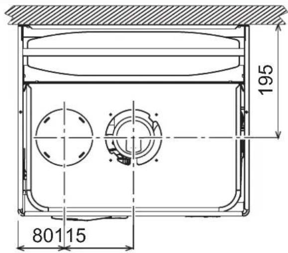
pnc.18-BuicBepxy
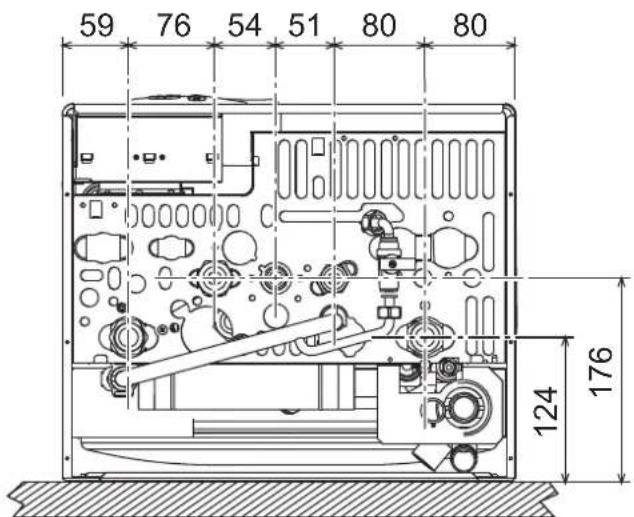
pnc.19-BudcHn3y
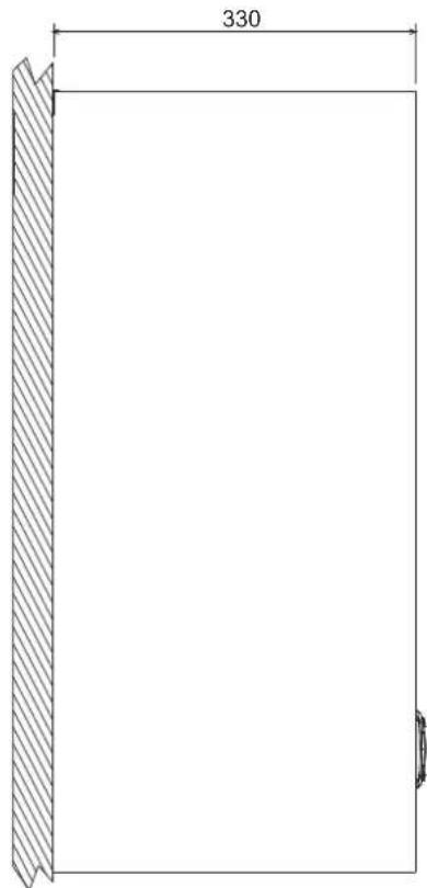
pnc.20-BnDc6oky
5.2 O6wn BnD n oCHOBHbye3bl

pnc.21-06uBn
5.3 Cxema cncTeMbI OTONHeHn IBC
DEKJIAPAUIO IPO BIDNOIBHICTb MOXHA 3ANITATN Y BNPOEHNA.
2. IHCTPYKJi3 EKCIJYATAUJI
2.1PpeDCTaBHeHHa
JIO6'3Hn TOKynu
DIVAcondens F24/F28 - ue KOHdcaiHn Tennobn rehepato 3aKpnto KAMEPO, np3Hauehn dna Oanene Hb6o BpuO6HNTBa rapaoCANTEXHIOBdo, 3 BcOKMM KoepiciHem KOpCHOI Dk, KMK Monpe KaObaTHa n PnpOHOmy a60 cKpAneHOMy raai ochauehn mikponpoecOHO CTcEMHO KepyBaHH.
UEI PNIAD IDEAJIbHO IINXODHTB DIA NOEHNHRA 3 TPAIDNCHIM
BUCOKOTEMIPATYPHIMN CNTTEMAMN I HE MOXKE IOEJNYBATNCRA ABO BCTAHOBNIIBBATNCN PPARMOI NODAEHO HA CNTTEMAX 3 HN3bKOTEMIPATYPHIMN BINPOMIHIOHOUMN PAHEJIIMN.
2.2 NaHEnb ynpabJIHHa
PanheIb

MAN.1-PaHEnb KoHTpOIO
Ha dncnnei (no3.11 - man. 1) 3'ABNCTbC noTOH a TmnpaTy pNOaI oANeHH, nID Yac OkyBaHH a onaneHH 3'ABNCTbC hAnIC "d2".
CaTExHiUHa BODa
3aHHT HcTExHHy BDOY (A KINBHKNKAeTbC CNOKNaHHM rapHOI cHtexHHIO BDO) CynPOBdKyctcb 6nMaHHM HA dncnnei rapHOI BOO nonid kpaHOM BDOONCTAHHA.
Ha dncnei (no3. 11 - Man. 1) 3'ABnBcBc noToH aTemnepaTy a H bNxoI rapyoi BODi, nii cac oukyBaHH Ha TBII 3'ABnBcBc HAnic "d1".
Comfort (KoMΦopT)
3aHTHaComfort (peKHM KompOpy) (BiDHOBNEHH BHYTpHbSOI TEMNepATpyn KOTNa), cynpoBDXyctbc 6JIIMAHNNo3HaNN BOIN iN kpaHOM Ha DCNnei. Ha DCNnei (no3.11-Man. 1) AHNCTBC NOTOVA TMENPATpyo BOIN yKOTNI.
Henonakka
Ypasi HENONADKn (cap. 4.4DVB.) Ha DCNNEi3'ABNCTbC KoD HENONADKn 11-Man. 1niD Yac OUYBAAHNA (RkE BmnaTcBc6e3nekoIO) 3'ABNIObTCbHANNC "d3".
2.3 YbIMKHeHHI BIMnKaHH
HaTnCHiB KHONky on/off (no3.7 - Man. 1) Ha 5cekyHd.

MAN.2-BuMKHeHHKOTnA
Habitb y BIMKHEHOMY KOTNI eJNEKTPMHe JKBNEHHe HA eJNEKTPOHHy nnty. PekmOnaJIeHnra Ta rapHO BOJONCTAuaHHB BIMKHEO. PekmP o60Tn CNTEM npTOI 3aMeP3AHnHa 3aIIuMaTeCB aKTHOBaHM. INr NOPTOPHO BBIMKHEHn KOTJIa 3HOBY HATNCHTb KHONky on/off (No3-7.Ma1.1) Ha 5 cekyHd.
man.3
Koten 6yde heraHRO rotobn do p6oBtKoXHorO pa3y, KOJIN BiD6yBaCTbC nOKKaHnHra np40i BoDn a6o noctynae 3anit Ha onaneHHra (BID KIMHATHORo TepMOCTa A60 duTachuHOrO xpoHOCTa).

PnB BIDKIOUeHHI eNEKTPuHOrO KINBNeHHra Ta/a6o Ra3y BiD KOtNa CnCTema npOTn 3aMepeAHHa He npauOBaHmE. RaIO Bu He KOpNCTyBaTImEtCeK OTiOMBPOBDK TpBAnO Ro cacy B3MkY, ToDi, 0o6 3ano6birn Horo yUkoJKeHHO uepe3 aMeepaHHa, peKoMeHNyEcTBc 3NTN BCO Body 3 KOtNa -Rk 3 OnaIIHOBbHorO KOHTpy, taK i 3 KOtPyr FB1, a60 yBeCTn aHTnpn3 B onaIIBOaBHNI KOHTyp BiNDIO HO Do BkazibIO 3 sez. 3.3.
2.4 PerynIOBaan
IpeemnkaHria Estate/Inverno (JIto/3ma)
HaTnCHITb KhoNky Estate/Inverno (Jiro/3ma) (DVB.6-MaI.N.1) Ha 2 cekyHd.
Ha dncnnei cnanaxye no3haoka Estate (Ito) (10 - Man. 1): Kote npaiobaTHME NIIIE HA BUPBNEHcAHTEHIOHO BODN. Pekm po60TN CNTEMN pOITN 3amep3AHN 3aJIINIAEbCtARKINBOBAHIM.
IrackacyBaHHpeKIMyEstate(PiTo)3HOByHaTmCHITbKHONkyEstate/Inverno(PiTo/ 3Ma)6-Ma.1)Ha2cekyHd.
PeryIIOBaHHa TempepatypOnaJIeHHa
HaTCHITb KHONIK OANeHHRA (no3. 314 Man. 1) DnA 3MIHN TEMNepaTyPi BID MIHIMAbHOI 30°C Do MaKCMAmBHOI 80°C.
man.4
PerynobAHn Temnepatyp B cnctemi
HaTNCHTb KHONKn CNTeMn FBn (noa. 1 i 2 - Man. 1), uo6 3mHOBaTN Tempeatpy BID, MIMAlbHOI (40^) do MAkCMmaHbHOI (55^)

PerynoBaHHKimHathiOi Temnepatypn (3a DonomorIO KIMHATHORo TepmoCTATA, knn Noctaactcbc 3a OKpeMM 3aMOBNEHHM)
3a DonOMORO KIMHaTOro TepMOCTATA BCTAHOBITb 6aKaHy TEMnepatpy y npMiuieHHI. Y pasi BiCyTOHcKO KimHaTHOro TepMOCTAY Temnepatypy kOtNI dyntpymyBatncn ha 3aAanhOMHY 3HAeHHI cyTabKn.
PerynoBaHHa KimhaHTo TemepaTytn (3a DonomoroO DnctaHuiHoro xpoHOCTata, knn NoCTaAcTbC3 3a OKpeMm 3amOBHeHHm)
3a DonomoroIO DnctahuiHoro xpoHOCTATA BCTaHOITb 6aKaHy Temnepatypy y npimiuHEn. TmepeIpya y npimiuHHI perynIOBaTImeTbCn no 6kaHHo. 3a IHopmaueio zoao po60tn DnCTAHUIHoro xpoHOCTATy 3BepHtbcn Do BIDNOIBHOKepINHTBA KOpNCTYbaA.
Bn6ip ECO/COMFORT (EKOHOMI/KOMΦOPT)
Koten mac cneuaibn npncptpi, kyn 3a6e3neyec ndbuenceHy wbnkictb Bnpo6nehna rapaoycaHTexHIO BOI Ta KACMnabHNI KOMFOPTJNA KOPNCTYBAU. KonnpntpE aKTBNHM (peXmKOMFOPTY-COMFORT), BOA, IO MicNTbc y Kotni, niTprmycBpnpn BiDNOBIDH TEmnPepatyi, Oo DO3BOBNE HERaHO OTPMaTNr rapaybOyBaHa bHXODi 3 KOITNa npn BiDKPbNAHHKpaHy.
Kopnctybau moke BmKHytn npncpti (ekOHOMHHnn pexkM ECO),HaTnCHyBn Ha KHONKY eco/comfort(no3.7 - Man.1).Bpexkmi EKOHOMII - ECO Ha dncnnei 3'ABnEeTcB CnBbON ECO (no3.12 -Man.1).ДЯ yBIMKHeHn peXkMy COMFORT (Kompopt) 3HOBy HATNCHTb KONky eco/comfort (ekOHOMIA/Kompopt)(no3.7 - Man.1).
PerynHOBAHH3 dIcTahuiHoro xpoHOCTaTy

Ppi niEHaHHI do KOTna DnCTaHuiHoro xpoHOCTaTy (RkN e onuicO) peryIOBAAH, ONCAHI BIne, 3dINCHIOHTbC 3rIdHO do Ta6nmu 1.
Tabnue.1
| PeryuobAHnRA TEmpeAtpyr ohaneHnRA | PeryuobAHnRA MOXHA 3dJIChmTI RIK 3 MEHIO dIcTAHIIHO rXPOHOCTATy, TAK I 3 naHEnI KOMAnD KOITNA. |
| PeryuobAHnRA TEmpeAtpyr rapaOoi cANTexHniHOI BOi | PeryuobAHnRA MOXHA 3dJIChmTI RIK 3 MEHIO dIcTAHIIHO rXPOHOCTATy, TAK I 3 naHEnI KOMAnD KOITNA. |
| IpeMHKnAHnRA IIITO/3HMa (Estate/ Inverno) | PereMHnI IIITO (Estate) e pIpiOpIeTnHnI ⅢJQDo MOxNIMBIX 3aIHTIB naOHAnEHnI 3bOxy dIcTAHIIHO rXPOHOCTATy. |
| Bn6ip peKmMy ECO/COMFORT (EKOHOMIA/KOMΦOPT ) | Takmi Bn6ip MOXHa 3pOBeHn IINIe 3 naHEnI KOMAnD KOITNA. |
PeryIOBaHHr iipabNlHOro TnCKy y KOHTpyi onaJIeHHH
Tnck 3anpabneHH npx xnoDHomO kyoHpyi, knn 3'ABtBcHa nippoMeTI KOtna (no3. 17 - man. 1), mac ctaHOBtN 6bn3bKO 1,06ap. KkTO TnCK y cncTeMI ONyCTMI HNKHe 3a MIIHMAbHe 3HAeHHK, KOten 3ynHHbCBA, a HA DnCnNeI 3'ABtBcK KOd HENOnaIK F37. 3a DonomoroIO kpaH dna 3anpabneHH (no3. 1 Man. 6) nobepHb TnCK do nochatkoBOrO 3aueHH, HanpiKHi ci onepaui 3abXdn 3akPbaTe Kpan dny 3anpabneHH.
MaN.6-KpaHdIa3npabHeHHa
3. MOHTAX
3.1 3aralbi nooxehn
BCTAHOBNIOBATN KOTENIOBHHI NIIIEFAXIBLI BIDNOIBHOI KBANIOKALU 3DOTPIMAHHRM YCIX BKA3IBOK LIEI TEXHINHOI HCTPYKLI, BIMOF IIIOYTO 3AKOHOOABCTBAHALIOJIHNIX I MCIJEBHX HOPM, A TAKOX 3A PABANAMI FAPHOI TEXHINHOI PPAKTIKN.
3.2 Micue dnia MOHTAKY
KoHTyp 3ropHnArperaty repMeTHNO 109IOBOBAHNI BIDHOCHO npMIueHHN, DE BII BCTAOHNEHnI, I TOMO KOTEN MOKE BMKOPNCTOBYAATCnB 6Bdy-RAKOM pIMiueHHI. Ipote npMIUEHHN, B KOMY BCTAOHOBTOBc KOTEN, NOBHIHE MATIN DOCTATHO BEHTNIAIOI dI 3anOIBARHHN He63neuHHN CNTyaIyI y pasi HABITb HE3HaHORO BHTOKY rasy. U HopMA 6e3NeKN BM3HauHEn DApeKTHBOO CEE Ne 2009/142 dIra BCIX npaIOUHX na raI arperatIB, B TOMO YCNI I dIra TAK 3BaHNx arperatIB i 3akpntIO kamepoIO.
Kotem Moke npiaoBAty u YactkoBo 3axHHeomy Mici, 3riHO 3i cTahdaptom EN 297 np A6, npn MiHaJIbHI Tempepaty -5°C. PeKomeHcyetbc BCTaHOBTN Kotem nid CXHNO daxy, Ha BankOHIO a60 b 3axHHeiny Hiui.
YMiCiIyCTaHOBKnTAKOXHe NOBHHO 6yTN NINy,JeKo3aMMnCTnxpeey Ta MATEpianiB a60 arpecuBnHx ra3iB.
Koten npn3haeHm dna hactinho yctahOBKn Ta noCTaaybcra i3 ck6oO dnniNbduyBAHH. 3akpinitb cko6y do CTHH, 3riDHO BIDMTkAM, BK3aAHMM y Man.17, Ta nidiBcte KOTen. KpinneHHHa CTHI mac rapaHTyBatn CTIke i Hadiye TpymuYBaHH KOTNA.

KIIIO KOtEN B6yDoyBcYe M6Nl a60 MOHTyBcR 6OKOM, Tpe6a nepe6aunH npocTip d3HRTA zaxHCORO KOxyi HOpMaIbHOr BOHKONHnpoBt 3 TeHXHOrO 06CNYROBYAHn.
3.3IipotexhiHi niknueHHa
3ayBaXeHHa

306 3anobirn CTikahno Bodn Ha 3emnlo B pasi npebnueHH TCKy y KOHTpyo onaneHH, 3nB 3anobixHoro KNAnaHny TpeBa 3'EDnATn 3 NiKBHO 40 tybKO 36npanbHOi NocdyHH. Ihakwe, RkUO cnpaioBaHH 3nHBHO rKtanaHny npribedes do 3aJIbBAHH npimiuehHH, BpuObHK KOTNa He HcTeHMe BiDnOBiDaNbHoCTi.

Nepu Hk BIKOHyBaTH NIDKIIIOHENHNEpeKOHaIeCeY BiNobIdHOCTI aperaTa Ta nana, a Toak Bo KINoHaIe PeTeBHe ONUeHNH BCIX TpybONpOBoIB onAnIOBnBHoH CNTeMn.
BnKoHaTe nIDKnIOeHHN Do BiINOBiDHX WtUeepIB 3rIHO ManIOHky Man.19 Ta no3HaKam Ha camOMy KOTJI.
3aybaxenha: onanIOBaIbHn KOHTyp OCHaeeHn BHyTpIHIM nepenyckHM KnaHOM.
XapakTepeNCTKIN BODIN KOHTpyi onaJIeHHr
JIOO JOKCTKICb BOIN NpeBmUy 25° Fr (1°F = 10 ActHn Ha Minioh CaCO3),TOJI, 306 3ano6irny T yBoepHHo HAKNY y KOTNI, Heo6xIDHO BnKOpNCTOBaHTn CneuaIbHO 60bp6NeHY BoDy.
CnCTema npotn 3amep3aHHaHTnFpnn3Pi pinn, npcaadkn i cnoBInbHOBaqui Kopo3ii
B pasi Heo6xHnOCTI Do3B0eHb BxHBaN aHTnDp3nHi pINHN, npnaCdki i cnobJIbHbOaHi Kopo3ii, ane IJne 3a YMOBn HADAAHHraPahTII 3 60kix IbNOBmHb IA BinODJIHcTb JcE IpNDyKuIa Dn 6e3NeuHO rOpKtCYBaHn Ta HbCdYtCHb P3NkY ykuokHeh dIy TENNoo6MIHnka KOTNa a60 IhuXn KomNoHEHIT b/a60 MATEpiAIB KOTNa TA BCBoR OYCTaKYBaHHa. 3a6OpOHCTbCBA NKOpCTAHn AHTnDPnIHx pINH, npcaDok i cnobJIbHbOaH BKO3I 3aarbHoII di, he npdaTHnx dI BvBnHaB y TENOBHX CTmExMaT X CYMHc3 MATEpiAANM, BKNOPCTAHmY KOITNa TYCTATKYBaHHi.
3.4Пдкнουeyнra3y
Пдкlioченя raу Mae 3diiChIOBaTnCЯ Do BiIDnoBIDHoro WtUcyepy (INB. Man. 19) 3 dOPTIMAHNBMOR YIHHBO3AkoHOBADaCTBA, metaneBOH KOKpTOKHO TpybKOHO a60 rHuKYKIM UJAHROM i CUYJIbHOO CTIKHOO CTIJI, BCTaHOBIOHIOr Ra3OBY BBeHTNJI MIX KOTyPOM Ta KOTNI. PepeKOHaTeCya yIJIbHOCTI Ra3OBNX nDHaNb.
3.5 EnektpnHi ndknoeHHa
3ayBaKeHHa

ArperaT Maic nIcDnHyBaTncb Do epeKTHBHOI CnCTeMn 3a3eMeHHra, BIKOHaHOI 3doPMHAAHm npabn 6e3neKn. EpeKTUBHICTb Ta BiJNOBIDHCt b CnCTeMn 3a3eMeHHra Mae nepeBipatncnue faoxibum, BpuoBHK BIXnIae 6yIbky BiNooBlaNbHCTb 3a MoKNB1 36NIk BNACNIOK BIDcyTHOci T CnCTeMn 3a3eMeHHra.
Дяпідкінчehнdo enektprvyhoМepeksi KOTEN OCHaшени Кабелem Tmny "Y"63 weTcncel.ПлкінчehнdoMepeksi NOBnHMI MAtiФКСOBaHe 3'eHdN Ta DBOJONIOCHNI nepeMmKau 3 BIDCTAHNO MIX KOHTAKTAMU Μонаймehu 3 MM,pOtaTuOByIOCh 3anO6bKNHKn Ha 3A MIX KOTnOM Ta NlHiCn. BaxhoDToPIMyBatNCa nonpHOCTI (JIHIA:KOPVHBeBn Dpi/T HEHTPAJIb:CnHIpIT/3EMJIr:KoBTn-3eEHnDpi)B nID'eHaHHxdo eNETkrpvHoi liHII.

B KOMnTeHJIO KOpNCTyBaHa He BXoDnTb 3aMiHa Ka6eIIO XKINBHeHH. Y pa3i yUkoKdXeHHa Ka6eIIO BmKHTb arperaT, NotIM 3BepHTscra No DOnomory Do kBanlkiKobAHorO qaxibua. IInr 3aMIHN BHKOPNCTOBYtBe BKNIOHO Ka6eIb "HAR H05VV-F" 3x0,75 MM2, MaKcImaJIbHn DiAMetp RaKO He nepeBmUye 8 MM.
KimhaTHNI TepMoCTaT (onzi)

YBFA: KIMHATHNI TEPMOCTAT NOBUHE MATN BIIBHI KOHTAKTIN. NIKJIOHYOCH 230 B KOJEM KIMHATHAGO TEPMOCTATY, BN BE3NOBOPOTHO 3AUKOJNTE EJEKTOPOHYI NATY.
Pn niknIOeHHxpoHOCTaB abo TaMepy He bepitb XNBAHENHn DnX npNCPTOIB 3 ix pO3MKNAOHUX KOHTAKIB. 3a6E3neueHHn iX XNBNEHnAM NOBnHNO npOBODINcHpee36be3nocepeHn NiEcdHnro MepeXi abo 3a donOMHO BatapeB, B 3aneKHOcti BiD tiny arperata.
DocyndoKleMHOi naHeni
P1IcN3HITnpeDhBoi nAHeni 3a6e3neUyEbC8 Doctyn Do KEMHOI nAHeni. Po3aTuBbHH 3aTNCB Dn p3Hnx NiKIIIOHe HabeDeHe TAKO HA eNEKTpWHi cxEM Ha Man.24.
man.7-DocyndoKnemHOi naHeni
3.6 DnMoBi Tpy6oNpOBoAn
3ayBaKeHHa
ArperatHanexnTbDoTinyC"3repeMTHNOKamepoi npmmycoBOI TROIO, noaayo NobITp i BvBEDEHnBIDnpaBObAHx Ra3IB Ma0tbi ByTNiDkNHOeHI DoOthie 3 CTTEM BvBEDeHH /BCMOKTyBAHH, BKA3AHNX HNHE. Arperat CTanaptIOBaHO an poBOTNI 3 Dnaparmn Cny 6ydb-RAKX KOHfirpaui,OnncAHnx HA TabnHui 3 TeXHHMM xapakTePNCHTKAMn. Ppi UcbOMy MoKe 6Bytn, 10 DeRei KOHfirpaui 6Bydyb O5MeKeHH AHBNO, ABO He BiNDobATn 3aKaOHAM, Hopmam ABO MicueBMn npabuHaM. 9e do yCTAHOBKn YCTaKBYANHe nepeBipte I peteJIbHO dOtpmYntcB TaKHX pO3npAIXeHN. Kpim TorO, DtoPMYntecB npAky Po3aUyBAHH terPiinAHn BA CTII I aO b cTeni i MHInMbHO BICTAHTBI BIKOH, CTIN, BEHTNauJINHX OTBOPB, TOIO.
Iiaoparmu
IpaobTn KOTNa Heo6xINO BCTAHOBHTniaqpaarmu, 10 NOCTABNHOb3 HMMB KOMNTKl, 3rIOH BkazIBOK, npBedeHNX B TaBnXnXnXe.
DIO nIKIOHn Hpy6n IIN BIBeEHn BIDnpaobAHnx ra3iHEo6xHNO nepeBipHTn npabunlsHcTB BIKOPNCOYBAHOI iAiparmn (npn II BOKOPCTAHHI) Ta II npabunlhy yctahOBky. 3AmHa diaipparmn (no3.1 - Man.8) MaepnpoBDNTNcR3iHNO Do BKA3IBOKy man.8.
man.8

PiKIOeHHa 3a DonomoroIO cnibichx Tpy6
MaN.9-PnKnai nd KIOHHeHHa donomoro cnibichnx (koacianbHnx) Tpy6 ()=Piobitrpa/ BIDnpaubobani ra3n
Tabnua.2-Tunonorir
| Tin | Опсс. |
| C1X | 3abip noBIPr i BmYCK dmMIB roPn3OHTaJIbHn piNCTIHHN |
| C3X | 3abip noBIPr i BmYCK dmMIB veRtKanbHn daxoAHn |
Dnncibichoro npncdHaHn BCTaHOBt Ha arperati OIN 3 TaKnx NoaTkoBnx
enemTei. P03mpn dNn HACTHHX CBepeNHeb HadaHI Ha MaIOHKy HA o6KnAinuI. Dnna
3anooirHHo MOnkNBO 3BOpTOHn CTaKHn KOHNcHcAty 3OBI Hi KaPAnHH
Heo6PiHO, 06 MoKNI RopnOHTaBlHi YaCTAHN Tpy6onpoBodn DIn BIDBeEHn
BIDnpauBOHn Ra3IB BCTaHOHOBaHnC3 NekmHAXnOM B6ik KOTna
041002X0

041006X0

041001X0
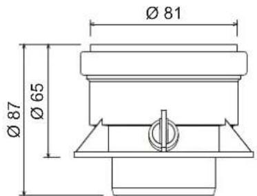
MAN.10-NoatkoBie enemeHTn Ia KoakciaIbHux Tpy6onpoBODIB
Ta6nua.3-DiaqparMn dna cnbicnXtpy6onpoBod
| DIVAcondens F24 | CnibicnH 60/100 | CnibicnH 80/125 | ||
| Мakcmaьна дзворета довхинa | 6 M | 12 M | ||
| Кофцient 3мншеник КСПИЗ 90° | 1 M | 0,5 M | ||
| Кофцient 3мншенин КСПИЗ 45° | 0,5 M | 0,25 M | ||
| Дiaфраима, як Нeoбхidно Викорисовати | 0ч 2 M | Ø45 | 0ч 6 M | Ø45 |
| 2ч 4 M | Ø50 | 6ч 12 M | Hemac diaparmm | |
| 4ч 6 M | Hemac diaparmm | |||
| DIVAcondens F28 | Cnibicn 60/100 | Cnibicn 80/125 | ||
| Мakcimamba на дзворета довхина | 4 M | 12 M | ||
| КофICIENT 3мEHненя кОПио 90° | 1 M | 0,5 M | ||
| КофICIENT 3мEHненя кОПио 45° | 0,5 M | 0,25 M | ||
| Дia酚aramа, як Нбхдно ВИKKONICSTOBYВATN | 0ч 2 M | ∅50 | 0ч 6 M | ∅50 |
| 2ч 4 M | Hemac diaparma | 6ч 12 M | Hemac diaparma | |
IiiknIOeHHa 3a DonomOrHO BIDOKpeMHeHx Tpy6
Ta6nua.4-Tunonorir
| Tin | Опис |
| C1X | Тубоврадд дзабусяр NOБРЯВI BIDDEDEHнBIDPAPCUBOAHN XRABIB ROPMOTANTBHy PMICTHHNN. |
| Терманни Na bIXOДYAMXMDAМOTB 6yIM bAOKHOENTPHHMM aBO TANMMI, zuO HbIMXKYOTc DO BIMNAYB | |
| СхIDHNYMOB BIRPY (He BILBELE 50 cm) | |
| C3X | Тубоврадд дзабуsid NOБРЯВI bIDPAPCUBOAHN RAIB AERITKHANBHN DAXOBH. TeRMHANI Na bIXOДYAMXODI,якдзC12 |
| C5X | 3a6ip NOБРЯВI BIDOKPMEHnH BIDBIDDEHнBIDPAPCUBOAHN RAIB PIPCTIHORO aBO daxOBTO TmPy i, y |
| 6yDy-bxOMY pAsi, B OTHAK 3 pI3HMN 3HNEHNM TMCK.Тубоврадд дзIDБDEHнBIDPAPCUBOAHN RAIB I AZSBYPO NOBPIE H NOBHNI POSTAIOBVAATNCRA H pOITINHEHNX CTIHAX | |
| C6X | 3a6ip NOБРЯВI I BIDDEHнBIDPAPCUBOAHN RAIB aZdoNOMOgK TpyB, capTAFIKOBAHNX OKPEmEN (EN 1856/1) |
| B2X | 3a6ip NOБРЯВI 3 PRIMIIeHHN 3 YCTAHOBeHm IM arperatom i BIDDEHнBIDPAPCUBOAHN RAIB pIPCTIHORO aBO daxOBTo Tmny |
| A BAKJIMBO - Y PIPMIUEHHI MAE 3A6E3IeYBYATNC HALEKHE BEHTIKOBAHHR |
IINI INIKIOHHe BIDOKPemJIeHX Tpy6oNpOBoDIB BCTHOBt Ha arperati TAKNI OHTKOBn enEMeH:
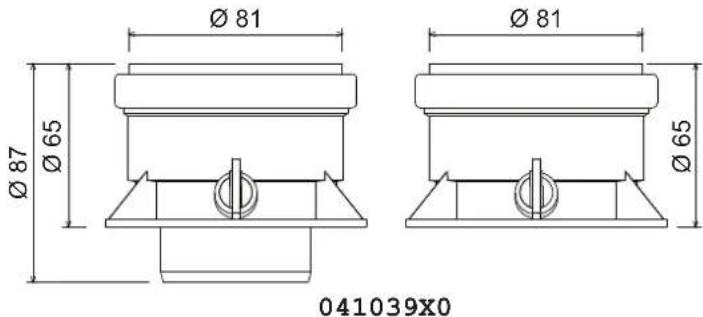
MAN.12 POnaTKOBn enemEn TnB BIDOKpEmneHx Tpy6onpoBodIB

IpeJyCTaHOBko nepeBiTe, 06 He nepeBnUyBaNacMaKcMmAbHo Do3BoneHa DOBXH;3pObit ce 3a DonOMorIO npocTOro pO3paxHyK:
- IIO BHICTIO Bn3HaTe CXemy CnCTeMn PO3DBoEHX NIMOXOIB, BKJIOaIOnH NOATKOBI ENEMEH i KIncEBi PnCTpOI (O6mExyBaui) HbNxoDi.
- 3eepHtbcra do Ta6nua 6i Bn3HaHTb BtpaB EKB. (ekBiaeneTHnx Metpax) dna KOxHoro KOMHOENTA, 3aJIeXHO BI nNOXeHHn Dn BCTaHOBHeHH.
- Npepeipte, no6 nobha cyma Btpat 6yna Hxkyo 3a MaKcMaIbHy DoBxHy a60 pIBHO i,do3BOeHII B Ta6nua 5.
Ta6nua.5-Diaaparmn nnBiodokpemenehTxpybopobod
NepuHix yBIMKHyTN KOTen
- YneBHHTbca y uinbHOCTI raoBOrO KOHTpy.
- IpeBipTe nDnip y po3wnpHOBaHbHOMy 6ky.
3anobHtB ripabnHm KOHTyp, 3a6e3neMbHn NobHm Bnpyck nobITpa 3 KOTna Ta 3 KOHTpy.
Pepbeipte, 606 He 6yno BtOkB OBDn B KOHTpyo anOHn, y KOHTpyax FBI, Ha 3EduHHx A60 y KOTNI.
IpepeBte npabnHbCtb niknoeHHra eKtpOCTaKyBaHHra ta pO6Oy cIcTeM33aMeHHH - PpeBipre, 06 3aHcHn TnCKy r3y dnn CnCTeMn onaneHH 6yIO TaKIM, k notpi6He.
Ipeepiepe, 656 y 6e3nocepeneHn 6n3bKocti Bid KOTna He 6yNo JERKOaMMCTNX piHN a60 MaTePianB
Ipebeipkn nid qac po6oTu
- YbimkhHt b arperat.
- YneBHItbcy uijbHocI KOHTpy roPiHH I BOaHnx CnCTem.
- Pnpe BIPrIe efeKTHBHCb DmMOxOy i nobITpRAHO-DmMOBux Tpy6oPBOBID niD ac po60TN KOTna.
PpokoHTponHoe npabunbHicb cnpkyraB Bodn MIX KOTlOM i CNTeMaMn.
YneBHITbca y ToM, 0r Ra3OBn Klanah npabInbHO npaOc k y pa3i onaneHH, Taki p3i npiroTyBaHHraP4HO caHTexHIO BOH.
IpeBiePte, nO6pe KOTen pO3nAIOE7cB, BmKOBAHn DEkINbKa npO6hNpO3nAIOBaH bIMNKaHb 3a DonOMORo KimHaTHOro TepMOCTara a60 dmCTAHUHOrO KEpyBaHH. - Ipebeipte BNTpaTn NAMBa 3a NINbHbNKOM Ta nopIBHnIe IX i3 3HAeHHnM y T6bnJIeTexHIHnx DAHN cap.5.
- PepeKoHaTeCRA, 50 63 3aNHTy Ha onaEnHn H aIbHn KopeKTHo po3aNHOeTcR np BIDKpTTI KpAHy 3 rapAHO BOHO. PepeKoHaTeCRA, 50 nDac pOBoTn Ha onaENHe, np BIDKpTTI KpAHy 3 rapAHO BOHO, 3ynHrEcR cUkpYlucHn HAcOC ONaENHH Ta BIKOHcyTcR npriOTyBaHH CaHTExHIO BoDn.
- PpeBipre npabnblHictb nporpamybaHHnapaMeTpib BkOhaHe Heo6xdne HanaTuBaHHA (KOMNEHCauHoi KPNBOI, NOTyXHOCT, TEmNepaTpyn, ToO).
4.3 Texhiye o6cnyrobyBaHHa
PepioHnn KOnTpOnlb
Ioo3a6e3neuHTn HanexHy n doBrotpbany po6Oty kOTna, pa3 Ha pik faxibui MaHOt bNkoHcyBaTu Taki nepeBipKn:
- Pnucptoi ynpabniHnI 6e3neKn (ra3OBn Klanah, Bntpatomip, Tepmoctatn, Too) nobHHnHyHKJIOHyBAtn npabNbHo.
KoHTypBbEeHnB BiDnpaBObaHnxra3IB NOBHeH MaTb 63dOrAHy eEeKtNBHICTb. (KOTen 3 aKpNTOHO KamepoHO:BENTNATOp,pene TCHky N0iTPRto,TOIO-3akPNTA kamepaMa6byTN repMeTHHO:uyinbHeHHa3aTNCaHi dIraKa6enib,TOIO).
(KoTeN 3 BIDKpTuO kAmepoIO: nepePbNAu Tarn, TePMocTa DmMOBnX ra3IB, ToO). - Nobitprno-HdNMOBI TpyBonpoBODNI orOIOBOKI (06MexyBaU) He noOBHHI MaTH nepeHKOJD BYTOKIB.
PnabHnK iTeIIOoMHHNK MAOTb 6yTN UcTmMn I 63 HAKNpy a60 Harapy. DnOuHcHnry y pa3i Heo6xioHocti He BkOpncToBouyTe ximKaTu a60 cTaneBi icITKn.
EneKtpoMa6 6ytN 6e3 Harpay i npabunbHO BCTaHOBnEM.
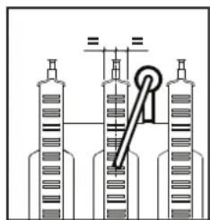

Ma1. 16 - Po3aWyBaHHe enekTpoDy
- Ra3OBI I BO4Hl CNTEMM MAOTb 6yTN UINbHMN.
TCK BOyu xOIOHm CnCTeMI Mae CTaHOBUN npN6n3Ho 16ap; kUo ue He TaK, NOBepHtB NOrO Do UbOro 3HaueHHA.
LupkyraHnHaocHe noBHe 6yT3a6nKOBAHM.
P03uipioBaIbHn6akMa6yTn3anpaBneHm
B n T prazyenoBHHI BIDnoBnAOK Bka3AHM y BiDNOBIDHNX TaBnucx.
4.4 YcynenHH HeCnPaBHOtei
Iiarhoctnka
Koten 6nbaHAno CuyachOIO CNCTeMO IO ABOTIOJHROCTNI. Y paai npoyweHHB po60ti KOTI DaCINNEE 6NMMATIME pa3OM 3 no3HaQHO HENONADKN (no3.11 - Man.1), BkA3yOHN Ha KOJ HENONADKN.
MaioTbca Taki HecnpabHocti, kci cnpuHHIOb noctHHe 6nkyBHHa (no3haehi nitepoo "A");IaB iINOBENHHPOBOT NOCTAHBO HATNCHNY KONKY RESET (no3.6 - man.1) ha 1 cekyHy afo KHONKY RESET dntanuHoro xpoHOCTaty (kyn e onuicO) b paai BmKOpNCtAHNOCTAHBO; kyo KOte He po3noHnae POboty, tpe6a ycHyTu nlo Henonadky.
HuiH HENONADKJIOK3HAHOTBCNITEPOHOF")CNPWHNHObT NIMACOB 3aBLOKYBAHJI,RAE 3HIMACTCBABOMATNUHO TINBKN-HO 3HAHEHHNnapametpy NOBEPTAeBHcY MEXI HOPMABHIOPO60THOTKOTNA.
Ta6JnHHeNoJaDOK
Ta6nua.8-HepepiK Henonao
5.XAPAKTEPNCNTKNA TEXHI DAHI
Ta6nua.9-ymoBbHn03HaueHHMa1.19,Man.21,Ma1.22i Man.23
5 3akpnta kamepa
7ПдбеннraуФ1/2"
8 BmKjBDn CNTeMn TBn0 1/2"
9 BxjB0n CHTeMn FBN 1/2
10 Ppma nihn (npa) kHTpy onaneH 3/4"
11 3BopOHa nHia KOHTpy onaneHHa 3/4"
14 3an6iKnnKnann
16 BeHTnIaTOp
19 Kamepa 3ropHHH
22 PJIbHnK
27 TennooMHHK 3 Mdi DnIaONaHEHHI npraHOr BOJDOCTAHAHH
28 Konektop bignpaobanx ra3iB
29 KoneKTOpIaBIDBeHnBaDpaauBaAHnxra3iB
32 LpkiyraiHn HaccKoHTpy onaneHH
34 DaTmK TemnepaTOn ananeHH
36 ABOMATIKHNI KIANBHN DRE BNYYCNY NOIBITPR
37 Φπbtp Bxody xonodHoi Bodn
38 Bntparomip
39 06mekyBaBn BHTpTaBn
42 DaTHK TEMNepaTpyB CACTEMFIBP
43 Pene racy nobirpa
44 Taogewknahan
49 3an06nHH TepMOCTAT
56 P03uHIOBaaHbHn6aK
74KpaHJr3aIIOBHeHHBOOIO CxCTEMM OIIaJIeHHH
81 EnektoPDoPAnaIOBAAHn? CNOCTeRbEeNzAaONyMn
95 Buidin nnan
114 Pene Tncky Bdo
187 Iiaepparma nna bijnpaabobahnx rasib
194 Tennoo6minHHK KOHTpy FBN
241 AromatimnnepeynycnHKnanaH (6ainac)
364PhiH npoT yBopEHHH KOHNCHcAY
5.1 Ra6apuTHi pO3mipn i nikloueHHa

man.17-Bnrrndcpepy