HR3530 - Drill MAKITA - Free user manual and instructions
Find the device manual for free HR3530 MAKITA in PDF.

Frequently Asked Questions - HR3530 MAKITA
User questions about HR3530 MAKITA
0 question about this device. Answer the ones you know or ask your own.
Ask a new question about this device
Download the instructions for your Drill in PDF format for free! Find your manual HR3530 - MAKITA and take your electronic device back in hand. On this page are published all the documents necessary for the use of your device. HR3530 by MAKITA.
USER MANUAL HR3530 MAKITA
GB Rotary Hammer Instruction manual
natural_image
Technical line drawing of a mechanical drill press with a tool and base (no text or symbols)
natural_image
Technical line drawing of a mechanical device with no visible text or symbols1
text_image
22
text_image
33
text_image
Technical diagram of a mechanical assembly with numbered parts labeled 4 and 54
natural_image
Line drawing of a drill bit with a spoke, shown in perspective view (no text or symbols)5
text_image
66
natural_image
Technical line drawing of a hand operating a welding torch with sparks flying (no text or symbols)7
text_image
7 88
text_image
99
natural_image
Line drawing of a precision drill bit with a pointed tool, shown in 3D perspective (no text or symbols)10
text_image
1011
ENGLISH
Explanation of general view
| 1. Switch trigger | 5. Depth gauge | 9. Center bit |
| 2. Side grip | 6. Blow-out bulb | 10. Rod |
| 3. Tool retainer | 7. Core bit | |
| 4. Clamp screw | 8. Adapter |
SPECIFICATIONS
| Model HR3530 | ||
| Capacities | Concrete 35 mm | |
| Core bit 105 mm | ||
| No load speed (min ^-1 ) | 760 | |
| Blows per minute 3,100 | ||
| Overall length | 374 mm | |
| Net weight | 5.3 kg | |
| Safety class | ☐/II | |
- Due to our continuing program of research and development, the specifications herein are subject to change without notice.
• Note: Specifications may differ from country to country.
Symbols
END201-3
The following show the symbols used for the equipment. Be sure that you understand their meaning before use.

..... Read instruction manual.

...... DOUBLE INSULATION
Intended use
ENE044-1
The tool is intended for hammer drilling in brick, concrete and stone as well as for chiselling work.
Power supply
ENF002-1
The tool should be connected only to a power supply of the same voltage as indicated on the nameplate, and can only be operated on single-phase AC supply. They are double-insulated in accordance with European Standard and can, therefore, also be used from sockets without earth wire.
SPECIFIC SAFETY RULES GEB007-2
DO NOT let comfort or familiarity with product (gained from repeated use) replace strict adherence to rotary hammer safety rules. If you use this tool unsafely or incorrectly, you can suffer serious personal injury.
- Wear ear protectors. Exposure to noise can cause hearing loss.
- Use auxiliary handles supplied with the tool. Loss of control can cause personal injury.
- Hold power tools by insulated gripping surfaces when performing an operation where the cutting tool may contact hidden wiring or its own cord. Contact with a "live" wire will make exposed metal parts of the tool "live" and shock the operator.
- Wear a hard hat (safety helmet), safety glasses and/or face shield. Ordinary eye or sun glasses are NOT safety glasses. It is also highly recommended that you wear a dust mask and thickly padded gloves.
- Be sure the bit is secured in place before operation.
- Under normal operation, the tool is designed to produce vibration. The screws can come loose easily, causing a breakdown or accident. Check tightness of screws carefully before operation.
- In cold weather or when the tool has not been used for a long time, let the tool warm up for a while by operating it under no load. This will loosen up the lubrication. Without proper warm-up, hammering operation is difficult.
- Always be sure you have a firm footing. Be sure no one is below when using the tool in high locations.
- Hold the tool firmly with both hands.
- Keep hands away from moving parts.
-
Do not leave the tool running. Operate the tool only when hand-held.
-
Do not point the tool at any one in the area when operating. The bit could fly out and injure someone seriously.
- Do not touch the bit or parts close to the bit immediately after operation; they may be extremely hot and could burn your skin.
- Some material contains chemicals which may be toxic. Take caution to prevent dust inhalation and skin contact. Follow material supplier safety data.
SAVE THESE INSTRUCTIONS.
WARNING:
MISUSE or failure to follow the safety rules stated in this instruction manual may cause serious personal injury.
FUNCTIONAL DESCRIPTION
CAUTION:
• Always be sure that the tool is switched off and unplugged before adjusting or checking function on the tool.
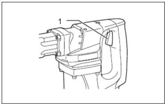
Switch action (Fig. 1)
CAUTION:
- Before plugging in the tool, always check to see that the switch trigger actuates properly and returns to the "OFF" position when released.
- Do not tape, tie or otherwise secure the trigger in the "ON" position.
To start the tool, simply pull the switch trigger. Release the switch trigger to stop.
ASSEMBLY
CAUTION:
• Always be sure that the tool is switched off and unplugged before carrying out any work on the tool.
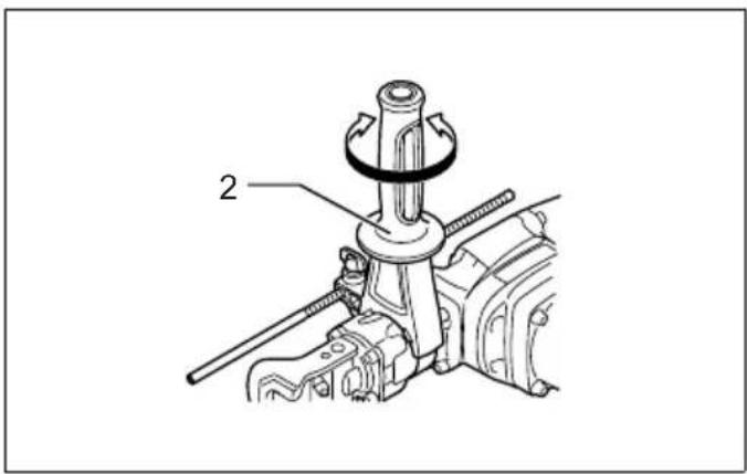
Side grip (auxiliary handle) (Fig. 2)
For maximum control and safer operation, always use the side grip with this tool. The side grip can be locked at four positions, horizontally and perpendicularly when the protrusion on the side grip base fits in the notch in the barrel (tool). Loosen the side grip by turning it counterclockwise, swing it to the desired position and then tighten it by turning clockwise.
Bit grease (optional accessory)
Coat the bit shank head beforehand with a small amount of bit grease (about 0.5 -1 g; 0.02 - 0.04 oz.). This chuck lubrication assures smooth action and longer service life.
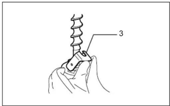
Installing or removing the bit (Fig. 3)
Pivot the tool retainer to the side. (If it is difficult to move the tool retainer with your thumbs, tap it with a hammer.) Insert the bit into the tool barrel as far as it will go.
Return the tool retainer to its original position to secure the bit.
To remove the bit, follow the installation procedure in reverse.
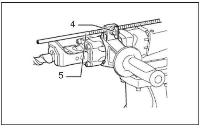
Depth gauge (Fig. 4)
The depth gauge is convenient for drilling holes of uniform depth. Loosen the clamp screw and adjust the depth gauge to the desired depth. After adjusting, tighten the clamp screw.
NOTE:
- The depth gauge cannot be used at the position where the depth gauge strikes against the gear housing.
OPERATION
CAUTION:
Always use the side grip (auxiliary handle) and firmly hold the tool by both side grip and switch handle during operations.
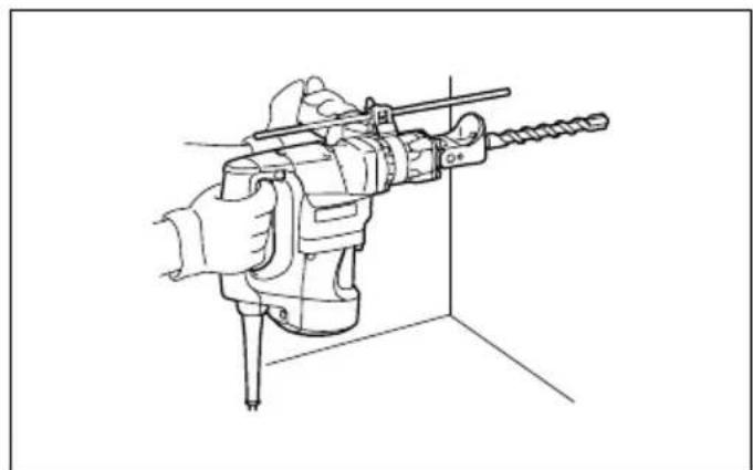
Hammer drilling operation (Fig. 5)
Position the bit at the desired location for the hole, then pull the switch trigger. Do not force the tool. Light pressure gives best results. Keep the tool in position and prevent it from slipping away from the hole. Do not apply more pressure when the hole becomes clogged with chips or particles. Instead, run the tool at an idle, then remove the bit partially from the hole. By repeating this several times, the hole will be cleaned out and normal drilling may be resumed.
CAUTION:
- When the bit begins to break through concrete or if the bit strikes reinforcing rods embedded in concrete, the tool may react dangerously. Maintain good balance and safe footing while holding the tool firmly with both hands to prevent dangerous reaction.
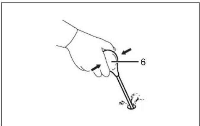
Blow-out bulb (optional accessory) (Fig. 6)
After drilling the hole, use the blow-out bulb to clean the dust out of the hole.
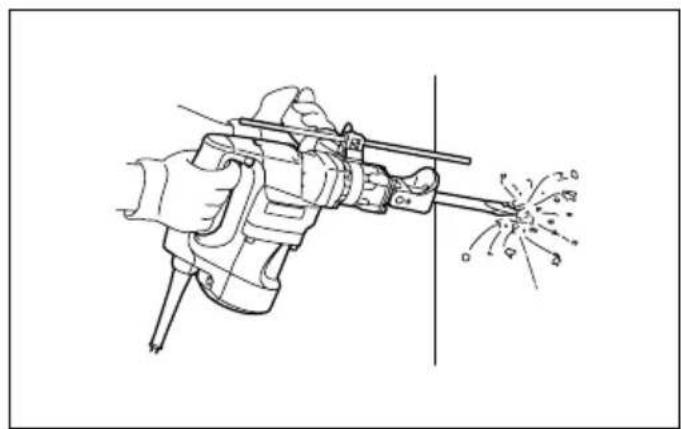
Chipping/Scaling/Demolition (Fig. 7)
Hold the tool firmly with both hands. Turn the tool on and apply slight pressure on the tool so that the tool will not bounce around, uncontrolled. Pressing very hard on the tool will not increase the efficiency.
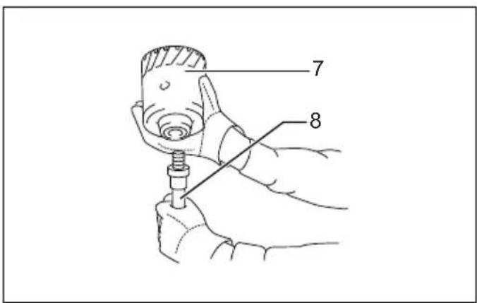
Core bit (optional accessory)
Screw the core bit on the adapter. Install the adapter with the core bit in the tool in the same manner as a drill bit.
(Fig. 8)
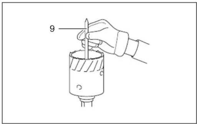
Install the center bit. (Fig. 9)
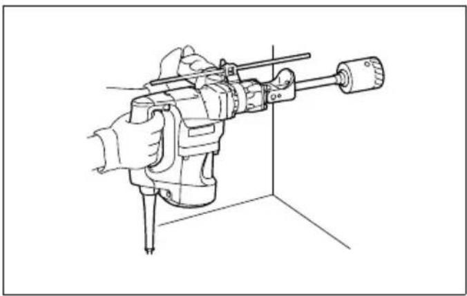
Rest the core bit on the concrete and turn the tool on.
Once the core bit has cut a shallow groove into the concrete, remove the center bit. Then resume drilling. (Fig. 10)
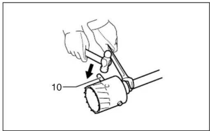
To remove the core bit, hold the adapter with the wrench, insert the rod (optional accessory) into the hole in the core bit and tap with a hammer to unscrew. (Fig. 11)
MAINTENANCE
CAUTION:
• Always be sure that the tool is switched off and unplugged before attempting to perform inspection or maintenance.
Lubrication
CAUTION:
- This servicing should be performed by Makita Authorized Service Centers only.
This tool requires no hourly or daily lubrication because it has a grease-packed lubrication system. It should be relubricated regularly. Send the complete tool to Makita Authorized Service Center for this lubrication service. To maintain product SAFETY and RELIABILITY, repairs, carbon brush inspection and replacement, any other maintenance or adjustment should be performed by Makita Authorized Service Centers, always using Makita replacement parts.
ACCESSORIES
CAUTION:
• These accessories or attachments are recommended for use with your Makita tool specified in this manual. The use of any other accessories or attachments might present a risk of injury to persons. Only use accessory or attachment for its stated purpose.
If you need any assistance for more details regarding these accessories, ask your local Makita Service Center.
• Tungsten carbide-tipped bit (Hexagonal)
• Tungsten carbide-tipped (hammer) bit
- Bull point
- Cold chisel
- Scaling chisel
- Clay spade
- Grooving chisel
- Rammer
- Bushing tool
• Hexagonal shank to various-Taper adapters
- Core bit
- Center bit
- Rod
- Core bit adapter
- Cotter (Drift key)
- Hammer grease
- Ground rod adapter
- Bit grease
FRANÇAIS
Descriptif
EC-DECLARATION OF CONFORMITY
Model; HR3530
ENH101-7
We declare under our sole responsibility that this product is in compliance with the following standards of standardized documents;
EN60745, EN55014, EN61000 in accordance with Council Directives, 2004/108/EC, 98/37/EC.
FRANÇAIS
DÉCLARATION DE CONFORMITÉ CE
Modèle ; HR3530
ENH101-7
Michigan Drive, Tongwell, Milton Keynes,
PORTUGUÊS
EN60745, EN55014, EN61000 de acordo com as
Directivas do Conselho, 2004/108/EC, 98/37/EC.
DANSK
EU-ERKLÆRING VEDR∅RENDE OVERHOLDELSE AF STANDARDER
Model: HR3530
ENH101-7
Michigan Drive, Tongwell, Milton Keynes,
Bucks MK15 8JD, ENGLAND
ENGLISH
For European countries only ENG102-1
Noise
The typical A-weighted noise level determined according to 60745-2-6:
Sound pressure level (LpA): 91 dB (A)
Sound power level ( L_WA ): 102 dB (A)
Uncertainty (K): 3 dB (A)
Wear ear protection
FRANÇAIS
Michigan Drive, Tongwell, Milton Keynes,
PORTUGUÊS
Apenas para os países europeus ENG102-1
Ruído
Michigan Drive, Tongwell, Milton Keynes,
Bucks MK15 8JD, ENGLAND
ENGLISH
Vibration ENG215-1
The vibration total value (tri-axial vector sum) determined according to EN60745-2-6:
Work mode: chiseling function
Vibration emission (ah, CHeq): 12.5 m/s²
Uncertainty (K): 1.5 m/s ^2
ENG303-1
Work mode: hammer drilling into concrete, 20 mm
diameter and 180 mm depth
Vibration emission (ah,HD): 19.5 m/s²
Uncertainty (K): 1.5 m/s²
FRANÇAIS
Vibration ENG215-1
Michigan Drive, Tongwell, Milton Keynes,
PORTUGUÊS
Vibração ENG215-1
Michigan Drive, Tongwell, Milton Keynes, Bucks MK15 8JD, ENGLAND
Makita Corporation
Anjo, Aichi, Japan
884739-998