6236D - Screwdriver MAKITA - Free user manual and instructions
Find the device manual for free 6236D MAKITA in PDF.

Frequently Asked Questions - 6236D MAKITA
User questions about 6236D MAKITA
0 question about this device. Answer the ones you know or ask your own.
Ask a new question about this device
Download the instructions for your Screwdriver in PDF format for free! Find your manual 6236D - MAKITA and take your electronic device back in hand. On this page are published all the documents necessary for the use of your device. 6236D by MAKITA.
USER MANUAL 6236D MAKITA
GB Cordless Driver Drill Instruction Manual
natural_image
Line drawing of a handheld electric drill (no text or symbols)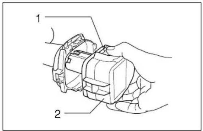
text_image
Technical diagram of a mechanical device with labeled parts 1 and 2, showing hands operating the component.1
text_image
2 3 42
text_image
5 6 7 83
text_image
5 94
text_image
105
text_image
11 12 13 14 156
text_image
16 17 187

text_image
19 20 21 228
natural_image
Line drawing of a mechanical tool tip inserted into a liquid, with no text or symbols present.9
text_image
2310
text_image
24 2511
ENGLISH
| Explanation of general view | ||
| 1 B u t t o n | 10 Switch trigger | 18 Speed change lever |
| 2 Battery cartridge | 11 Reversing switch lever | 19 Adjusting ring |
| 3 Charging light | 12 A side | 20 Graduations |
| 4 Battery charger | 13 B side | 21 Drill marking |
| 5 B i t | 14 Clockwise | 22 Pointer |
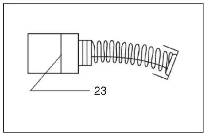
| 6 Tighten | 15 Counterclockwise | 23 Limit mark |
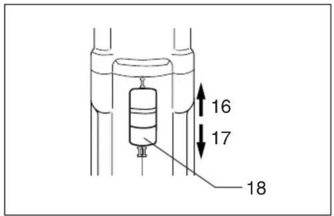
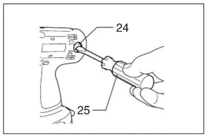
| 7 S l e e v e | 16 Low speed | 24 Brush holder cap |
| 8 Ring | 17 High speed | 25 Screwdriver |
| 9 Bit holder | ||
SPECIFICATIONS
Model 6216D 6236D 6316D 6336D
| Capacities | ||||
| Steel | 10 mm | 10 mm | 13 mm | 13 mm |
| Wood | 30 mm | 36 mm | 30 mm | 36 mm |
| Wood screw | 6 x 75 mm | 6 x 75 mm | 6 x 75 mm | 6 x 75 mm |
| Machine screw | 6 mm | 6 mm | 6 mm | 6 mm |
| No load speed (min ^-1 ) | ||||
| High | 0 – 1,300 | 0 – 1,300 | 0 – 1,300 | 0 – 1,300 |
| Low | 0 – 400 | 0 – 400 | 0 – 400 | 0 – 400 |
| Overall length | 243 mm | 243 mm | 255 mm | 255 mm |
| Net weight | 2.1 kg | 2.2 kg | 2.2 kg | 2.3 kg |
| Rated voltage | D.C. 12 V | D.C. 14.4 V | D.C. 12 V | D.C. 14.4 V |
- Due to our continuing program of research and development, the specifications herein are subject to change without notice.
- Note: Specifications may differ from country to country.
Safety hints
For your own safety, please refer to enclosed safety instructions.
IMPORTANT SAFETY INSTRUCTIONS FOR CHARGER & BATTERY CARTRIDGE
ENC001-3
- SAVE THESE INSTRUCTIONS — This manual contains important safety and operating instructions for battery charger.
- Before using battery charger, read all instructions and cautionary markings on (1) battery charger, (2) battery, and (3) product using battery.
- CAUTION — To reduce risk of injury, charge only MAKITA type rechargeable batteries. Other types of batteries may burst causing personal injury and damage.
- Do not expose charger to rain or snow.
- Use of an attachment not recommended or sold by the battery charger manufacturer may result in a risk of fire, electric shock, or injury to persons.
- To reduce risk of damage to electric plug and cord, pull by plug rather than cord when disconnecting charger.
- Make sure cord is located so that it will not be stepped on, tripped over, or otherwise subjected to damage or stress.
-
Do not operate charger with damaged cord or plug — replace them immediately.
-
Do not operate charger if it has received a sharp blow, been dropped, or otherwise damaged in any way; take it to a qualified serviceman.
- Do not disassemble charger or battery cartridge; take it to a qualified serviceman when service or repair is required. Incorrect reassembly may result in a risk of electric shock or fire.
- To reduce risk of electric shock, unplug charger from outlet before attempting any maintenance or cleaning. Turning off controls will not reduce this risk.
- The battery charger is not intended for use by young children or infirm persons without supervision.
- Young children should be supervised to ensure that they do not play with the battery charger.
- If operating time has become excessively shorter, stop operating immediately. It may result in a risk of overheating, possible burns and even an explosion.
- If electrolyte gets into your eyes, rinse them out with clear water and seek medical attention right away. It may result in loss of your eyesight.
ADDITIONAL SAFETY RULES FOR CHARGER & BATTERY CARTRIDGE
- Do not charge Battery Cartridge when temperature is BELOW 10^ C ( 50^ F) or ABOVE 40^ C ( 104^ F).
- Do not attempt to use a step-up transformer, an engine generator or DC power receptacle.
- Do not allow anything to cover or clog the charger vents.
-
Always cover the battery terminals with the battery cover when the battery cartridge is not used.
-
Do not short the battery cartridge:
(1) Do not touch the terminals with any conductive material.
(2) Avoid storing battery cartridge in a container with other metal objects such as nails, coins, etc.
(3) Do not expose battery cartridge to water or rain.
A battery short can cause a large current flow, overheating, possible burns and even a breakdown.
- Do not store the tool and battery cartridge in locations where the temperature may reach or exceed 50^ C ( 122^ F).
- Do not incinerate the battery cartridge even if it is severely damaged or is completely worn out. The battery cartridge can explode in a fire.
- Be careful not to drop, shake or strike battery.
- Do not charge inside a box or container of any kind. The battery must be placed in a well ventilated area during charging.
ADDITIONAL SAFETY RULES FOR TOOL
ENB022-1
- Be aware that this tool is always in an operating condition, because it does not have to be plugged into an electrical outlet.
- Hold tool by insulated gripping surfaces when performing an operation where the cutting tool may contact hidden wiring. Contact with a "live" wire will also make exposed metal parts of the tool "live" and shock the operator.
Charging (Fig. 2)
Plug the battery charger into the proper A/C voltage source. The charging light will flash in green color. Insert the battery cartridge so that the plus and minus terminals on the battery cartridge are on the same sides as their respective markings on the battery charger. Insert the cartridge fully into the port so that it rests on the charger port floor. When the battery cartridge is inserted, the charging light color will change from green to red and charging will begin. The charging light will remain lit steadily during charging. When the charging light color changes from red to green, the charging cycle is complete. If you leave the battery cartridge in the charger after the charging cycle is complete, the charger will switch into its “trickle charge (maintenance charge)” mode. After charging, unplug the charger from the power source.
Refer to the table below for the charging time.
| Battery type Capacity (Ah) Number of cells Charging time | ||||
| 1222 | (Ni-cd) | 2.0 | 10 | Approx.45 |
| 1233 | (Ni-MH) | 2.2 | 10 | Approx. |
| 1234 | (Ni-MH) | 2.6 | 10 | Approx.60 |
| 1235 | (Ni-MH) | 3.0 | 10 | Approx. |
| 1422 | (Ni-cd) | 2.0 | 12 | Approx.45 |
| 1433 | (Ni-MH) | 2.2 | 12 | Approx. |
| 1434 | (Ni-MH) | 2.6 | 12 | Approx.60 |
| 1435 | (Ni-MH) | 3.0 | 12 | Approx. |
CAUTION:
- The battery charger is for charging Makita battery cartridge. Never use it for other purposes or for other manufacturer's batteries.
-
When you charge a new battery cartridge or a battery cartridge which has not been used for a long period of time, it may not accept a full charge. This is a normal condition and does not indicate a problem. You can recharge the battery cartridge fully after discharging it completely and recharging a couple of times.
-
Always be sure you have a firm footing.
- Be sure no one is below when using the tool in high locations.
- Hole the tool firmly.
- Keep hands away from rotating parts.
- Do not leave the tool running. Operate the tool only when hand-held.
- Do not touch the drill bit or the workpiece immediately after operation; they may be extremely hot and could burn your skin.
SAVE THESE INSTRUCTIONS.
OPERATING INSTRUCTIONS
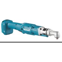
Installing or removing battery cartridge (Fig. 1)
- Always switch off the tool before insertion or removal of the battery cartridge.
- To remove the battery cartridge, withdraw it from the tool while pressing the buttons on both sides of the cartridge.
- To insert the battery cartridge, align the tongue on the battery cartridge with the groove in the housing and slip it into place. Always insert it all the way until it locks in place with a little click. If not, it may accidentally fall out of the tool, causing injury to you or someone around you.
-
Do not use force when inserting the battery cartridge. If the cartridge does not slide in easily, it is not being inserted correctly.
-
If you charge a battery cartridge from a just-operated tool or a battery cartridge which has been left in a location exposed to direct sunlight or heat for a long time, the charging light may flash in red color. If this occurs, wait for a while. Charging will begin after the battery cartridge cools. The battery cartridge will cool faster if you remove the battery cartridge from the battery charger.
- If the charging light flashes alternately in green and red color, a problem exists and charging is not possible. The terminals on the charger or battery cartridge are clogged with dust or the battery cartridge is worn out or damaged.
Trickle charge (Maintenance charge)
If you leave the battery cartridge in the charger to prevent spontaneous discharging after full charge, the charger will switch into its “trickle charge (maintenance charge)” mode and keep the battery cartridge fresh and fully charged.
Tips for maintaining maximum battery life
-
Charge the battery cartridge before completely discharged.
Always stop tool operation and charge the battery cartridge when you notice less tool power. -
Never recharge a fully charged battery cartridge.
Overcharging shortens the battery service life.
- Charge the battery cartridge with room temperature at 10^ C – 40^ C ( 50^ F – 104^ F).
Let a hot battery cartridge cool down before charging it.
- Charge the Nickel Metal Hydride battery cartridge when you do not use it for more than six months.
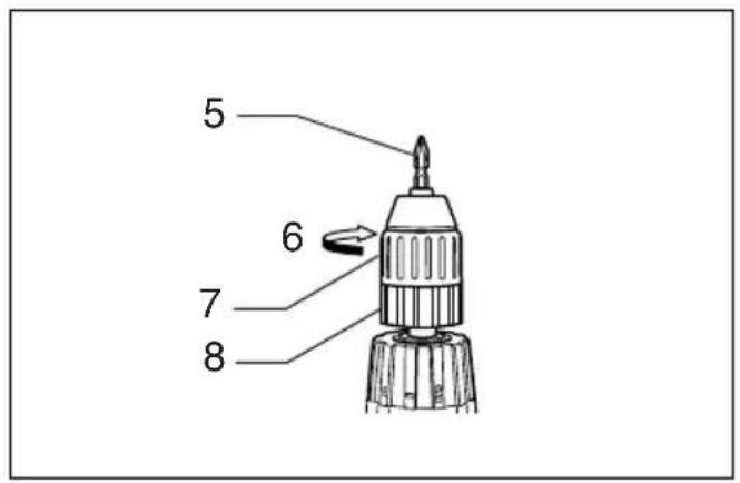
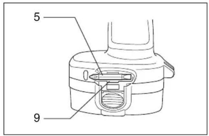
Installing or removing driver bit or drill bit (Fig. 3 & 4)
Important:
Always be sure that the tool is switched off and the battery cartridge is removed before installing or removing the bit.
Hold the ring and turn the sleeve counterclockwise to open the chuck jaws. Place the bit in the chuck as far as it will go. Hold the ring firmly and turn the sleeve clockwise to tighten the chuck.
To remove the bit, hold the ring and turn the sleeve counterclockwise. When not using the driver bit, keep it in the bit holders. Bits 45 mm long can be kept there.
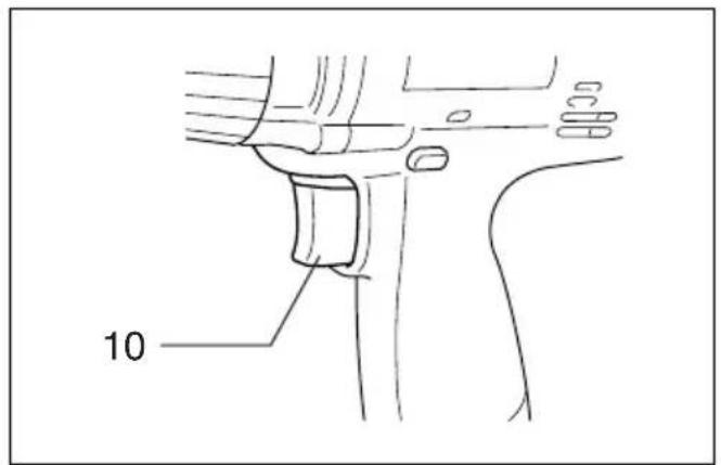
Switch action (Fig. 5)
CAUTION:
Before inserting the battery cartridge into the tool, always check to see that the switch trigger actuates properly and returns to the "OFF" position when released.
To start the tool, simply pull the trigger. Tool speed is increased by increasing pressure on the trigger. Release the trigger to stop.
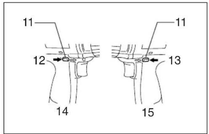
Reversing switch action (Fig. 6)
CAUTION:
- Always check the direction of rotation before operation.
- Use the reversing switch only after the tool comes to a complete stop. Changing the direction of rotation before the tool stops may damage the tool.
- When not operating the tool, always set the reversing switch lever to the neutral position.
This tool has a reversing switch to change the direction of rotation. Depress the reversing switch lever from the A side for clockwise rotation or from the B side for counterclockwise rotation. When the switch lever is in the neutral position, the switch trigger cannot be pulled.
Speed change (Fig. 7)
To change the speed, first switch off the tool and then slide the speed change lever to the "II" side for high speed or "I" side for low speed. Be sure that the speed change lever is set to the correct position before operation. Use the right speed for your job.
CAUTION:
- Always set the speed change lever fully to the correct position. If you operate the tool with the speed change lever positioned half-way between the “I” side and “II” side, the tool may be damaged.
- Do not use the speed change lever while the tool is running. The tool may be damaged.
Adjusting the fastening torque (Fig. 8)
The fastening torque can be adjusted in 17 steps by turning the adjusting ring so that its graduations are aligned with the pointer on the tool body. The fastening torque is minimum when the number 1 is aligned with the pointer, and maximum when the ⏻ marking is aligned with the pointer.
The clutch will slip at various torque levels when set at the number 1 to 16. The clutch is designed not to slip at the marking.
Before actual operation, drive a trial screw into your material or a piece of duplicate material to determine which torque level is required for a particular application.
NOTE:
- The adjusting ring does not lock when the pointer is positioned only half-way between the graduations.
- Do not operate the tool with the adjusting ring set between the number 16 and the ⏻ marking. The tool may be damaged.
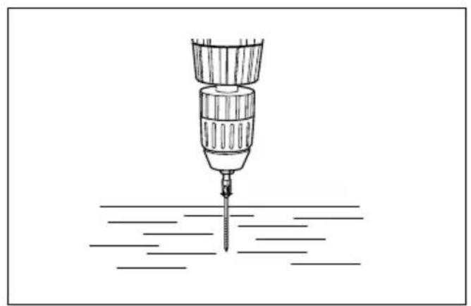
Screwdriving operation (Fig. 9)
Place the point of the driver bit in the screw head and apply pressure to the tool. Start the tool slowly and then increase the speed gradually. Release the trigger as soon as the clutch cuts in.
NOTE:
- Make sure that the driver bit is inserted straight in the screw head, or the screw and/or bit may be damaged.
- When driving wood screws, predrill pilot holes to make driving easier and to prevent splitting of the workpiece. See the chart below.
| Nominal diameter of wood screw (mm) | Recommended size of pilot hole (mm) |
| 3.1 2.0–2.2 | |
| 3.5 2.2–2.5 | |
| 3.8 2.5–2.8 | |
| 4.5 2.9–3.2 | |
| 4.8 3.1–3.4 | |
| 5.1 3.3–3.6 | |
| 5.5 3.7–3.9 | |
| 5.8 4.0–4.2 | |
| 6.1 4.2–4.4 |
- If the tool is operated continuously until the battery cartridge has discharged, allow the tool to rest for 15 minutes before proceeding with a fresh battery.
Drilling operation
First, turn the adjusting ring so that the pointer on the tool body points to the ⏻ marking. Then proceed as follows.
- Drilling in wood
When drilling in wood, best results are obtained with wood drills equipped with a guide screw. The guide screw makes drilling easier by pulling the bit into the workpiece.
- Drilling in metal
To prevent the bit from slipping when starting a hole, make an indentation with a centerpunch and hammer at the point to be drilled. Place the point of the bit in the indentation and start drilling. Use a cutting lubricant when drilling metals. The exceptions are iron and brass which should be drilled dry.
CAUTION:
- Pressing excessively on the tool will not speed up the drilling. In fact, this excessive pressure will only serve to damage the tip of your bit, decrease the tool performance and shorten the service life of the tool.
- There is a tremendous force exerted on the tool/bit at the time of hole breakthrough. Hold the tool firmly and exert care when the bit begins to break through the workpiece.
- A stuck bit can be removed simply by setting the reversing switch to reverse rotation in order to back out. However, the tool may back out abruptly if you do not hold it firmly.
- Always secure small workpieces in a vise or similar hold-down device.
- If the tool is operated continuously until the battery cartridge has discharged, allow the tool to rest for 15 minutes before proceeding with a fresh battery.
MAINTENANCE
CAUTION:
Always be sure that the tool is switched off and the battery cartridge is removed before carrying out any work on the tool.
Replacement of carbon brushes (Fig. 10 & 11)
Replace carbon brushes when they are worn down to the limit mark. Both identical carbon brushes should be replaced at the same time.
To maintain product safety and reliability, repairs, maintenance or adjustment should be carried out by a Makita Authorized Service Center.
ACCESSORIES
CAUTION:
- These accessories or attachments are recommended for use with your Makita tool specified in this manual. The use of any other accessories or attachments might present a risk of injury to persons. Only use accessory or attachment for its stated purpose.
If you need any assistance for more details regarding these accessories, ask your local Makita service center.
- Screw bits
- Grip assembly
- Rubber pad assembly
- Foam polishing pad
- Depth gauge
- Wool bonnet
- Various type of Makita genuine batteries and chargers
- Plastic carrying case
Descriptif
- Plastic draagkoffer
ESPAÑOL
EC-DECLARATION OF CONFORMITY
We declare under our sole responsibility that this product is in compliance with the following standards of standardized documents,
EN50260, EN55014
in accordance with Council Directives, 89/336/EEC and 98/37/EC.
FRANÇAISE
DÉCLARATION DE CONFORMITÉ CE
EU-DEKLARATION OM KONFORMITET
Michigan Drive, Tongwell, Milton Keynes,
Bucks MK15 8JD, ENGLAND
ENGLISH
EC-DECLARATION OF CONFORMITY
We declare under our sole responsibility that this product is in compliance with the following standards of standardized documents, EN60335, EN55014, EN61000
in accordance with Council Directives, 73/23/EEC and 89/336/EEC.
FRANÇAISE
DÉCLARATION DE CONFORMITÉ CE
EU-DEKLARATION OM KONFORMITET
Michigan Drive, Tongwell, Milton Keynes,
Bucks MK15 8JD, ENGLAND
ENGLISH
Noise and Vibration
The typical A-weighted sound pressure level is 71 dB (A).
The noise level under working may exceed 85 dB (A).
- Wear ear protection. -
The typical weighted root mean square acceleration value is not more than 2.5 m/s^2 .