
6841R - Screwdriver MAKITA - Free user manual and instructions
Find the device manual for free 6841R MAKITA in PDF.

| Product Type | Screwdriver |
| Brand | Makita |
| Model | 6841R |
| Power Source | Corded electric |
| Input Voltage | 230 V AC |
| Power Consumption | 650 W |
| No Load Speed | 0 - 600 rpm |
| Chuck Type | Hexagonal (1/4 inch / 6.35 mm) |
| Max Fastening Torque | 40 Nm |
| Reversible Rotation | Yes |
| Variable Speed Trigger | Yes |
| Depth Adjustment | Yes, with depth stop |
| Overall Dimensions (L x W x H) | 270 mm x 65 mm x 210 mm |
| Weight | 1.5 kg |
| Power Cord Length | 2.5 m |
| Protection Class | Class II (double insulation) |
| Maintenance | Clean with dry cloth; check carbon brushes periodically |
| Safety Features | Lock-on button, thermal overload protection |
| Repairability | Spare parts available; user-replaceable brushes and switch |
Frequently Asked Questions - 6841R MAKITA
User questions about 6841R MAKITA
0 question about this device. Answer the ones you know or ask your own.
Ask a new question about this device
Download the instructions for your Screwdriver in PDF format for free! Find your manual 6841R - MAKITA and take your electronic device back in hand. On this page are published all the documents necessary for the use of your device. 6841R by MAKITA.
USER MANUAL 6841R MAKITA
GB Auto Feed Screwdriver INSTRUCTION MANUAL
| UA | Шуруповерт із автоматичним подаванням | ІНСТРУКЦІЯ З ЕКСПЛУАТАЦІЇ |
| PL | Wkrętarka z magazynkiem | INSTRUKCJA OBSŁUGI |
| RO | Maşină de înşurubat cu alimentare automată | MANUAL DE INSTRUCTIUNI |
| DE | Magazin-Schnellbauschrauber | BEDIENUNGSANLEITUNG |
| HU | Önetető csavarbehajtó | HASZNÁLATI KÉZIKÖNYV |
| SK | Skrutkovač s automatickým podávaním | NÁVOD NA OBSLUHU |
| CZ | Šroubovák se zásobníkem NÁVOD K OBSLUZE | |
6841R
natural_image
Technical line drawing of a mounted optical instrument with visible components and no text or symbols
1
2
3
4
5
6
7
8
9
1 0
1 1
1 2
1 3
natural_image
Mechanical assembly diagram showing internal components and motion direction (no text or labels)1 4
1 5
natural_image
Illustration of a hand using a tool to adjust or install a mechanical component (no text or symbols visible)1 6
natural_image
Technical line drawing of a mechanical device with labeled component (no text or symbols)17
natural_image
Technical line drawing of a mechanical device with hands operating it (no text or symbols present)18
natural_image
Pure mechanical diagram showing a spring-loaded component with no text or symbols1 9
20
009828
ENGLISH (Original instructions)
Explanation of general view
| 1-1. Lock button | 6-1. Lever | 11-2. Magazine cap |
| 1-2. Switch trigger | 6-2. Stopper base | 12-1. Portion A |
| 2-1. Reversing switch lever | 6-3. Plate | 13-1. Screw-driving position |
| 3-1. Hook | 6-4. Casing | 15-1. Reverse lever |
| 3-2. Clamping screw | 8-1. Lock lever | 16-1. Protrusion (A) |
| 4-1. Casing | 8-2. Magazine cap | 17-1. Extension handle |
| 4-2. Thumb screw | 9-1. Screw strip | 19-1. Limit mark |
| 5-1. Plane bearing | 9-2. Magazine | 20-1. Brush holder cap |
| 5-2. Dust cover | 10-1. Slotted passage | 20-2. Screwdriver |
| 5-3. Bit | 11-1. Lock lever |
SPECIFICATIONS
| Model | 6841R |
| Screw strip 4 mm x 25 mm - 41 mm | |
| No load speed (min ^-1 ) | 6,000 |
| Overall length 333 mm | |
| Net weight 2.0 kg | |
| Safety class /II | ☒ |
- Due to our continuing programme of research and development, the specifications herein are subject to change without notice.
- Specifications may differ from country to country.
• Weight according to EPTA-Procedure 01/2003
ENE033-1
Intended use
The tool is intended for screw driving in wood, metal and plastic.
ENF002-2
Power supply
The tool should be connected only to a power supply of the same voltage as indicated on the nameplate, and can only be operated on single-phase AC supply. They are double-insulated and can, therefore, also be used from sockets without earth wire.
ENG905-1
Noise
The typical A-weighted noise level determined according to EN60745:
Sound pressure level ( L_pA ): 83 dB(A)
Sound power level ( L_WA ): 94 dB(A)
Uncertainty (K) : 3 dB(A)
Wear ear protection
ENG900-1
Vibration
The vibration total value (tri-axial vector sum) determined according to EN60745:
Work mode: screwdriving without impact
Vibration emission ( a_h ): 2.5 m/s ^2 or less
Uncertainty (K) : 1.5 m/s ^2
ENG901-1
- The declared vibration emission value has been measured in accordance with the standard test method and may be used for comparing one tool
with another.
- The declared vibration emission value may also be used in a preliminary assessment of exposure.
WARNING:
- The vibration emission during actual use of the power tool can differ from the declared emission value depending on the ways in which the tool is used.
- Be sure to identify safety measures to protect the operator that are based on an estimation of exposure in the actual conditions of use (taking account of all parts of the operating cycle such as the times when the tool is switched off and when it is running idle in addition to the trigger time).
ENH101-15
For European countries only
EC Declaration of Conformity
We Makita Corporation as the responsible manufacturer declare that the following Makita machine(s):
Designation of Machine:
Auto Feed Screwdriver
Model No./ Type: 6841R
are of series production and
Conforms to the following European Directives: 2006/42/EC
And are manufactured in accordance with the following standards or standardised documents: EN60745
The technical documentation is kept by our authorised representative in Europe who is:
Makita International Europe Ltd.
Michigan Drive, Tongwell,
Milton Keynes, Bucks MK15 8JD, England
30.1.2009
000230
Tomoyasu Kato
Director
Makita Corporation
3-11-8, Sumiyoshi-cho,
Anjo, Aichi, 446-8502, JAPAN
GEA010-1
General Power Tool Safety Warnings
⚠ WARNING Read all safety warnings and all instructions. Failure to follow the warnings and instructions may result in electric shock, fire and/or serious injury.
Save all warnings and instructions for future reference.
GEB017-4
SCREWDRIVER SAFETY WARNINGS
- Hold power tool by insulated gripping surfaces, when performing an operation where the fastener may contact hidden wiring or its own cord. Fasteners contacting a "live" wire may make exposed metal parts of the power tool "live" and could give the operator an electric shock.
- Always be sure you have a firm footing. Be sure no one is below when using the tool in high locations.
- Hold the tool firmly.
- Keep hands away from rotating parts.
- Do not touch the bit or the workpiece immediately after operation; they may be extremely hot and could burn your skin.
SAVE THESE INSTRUCTIONS.
⚠ WARNING:
DO NOT let comfort or familiarity with product (gained from repeated use) replace strict adherence to safety rules for the subject product. MISUSE or failure to follow the safety rules stated in this instruction manual may cause serious personal injury.
FUNCTIONAL DESCRIPTION
CAUTION:
- Always be sure that the tool is switched off and unplugged before adjusting or checking function on the tool.
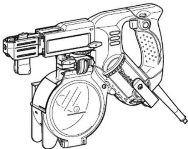
Switch action
Fig.1
CAUTION:
- Before plugging in the tool, always check to see that the switch trigger actuates properly and returns to the "OFF" position when released.
To start the tool, simply pull the switch trigger. Release the switch trigger to stop.
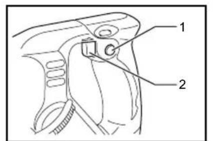
Reversing switch action
Fig.2
This tool has a reversing switch to change the direction of rotation. Depress the reversing switch lever from the A side for clockwise rotation or from the B side for counterclockwise rotation.
CAUTION:
- Always check the direction of rotation before operation.
- Use the reversing switch only after the tool comes to a complete stop. Changing the direction of rotation before the tool stops may damage the tool.
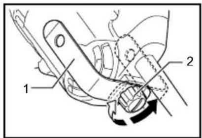
Hook
Fig.3
The hook is convenient for hooking the tool to your belt. It can be installed on either side of the tool.
Changing the installation position of hook allows two-way setting of 10 mm and 20 mm distance from the tool itself. The tool with hook can be hung on the waist belt, a maximum diameter 20 mm pipe etc.
To remove the hook, just remove the clamping screw. Place it on the tool and secure it with the clamping screw to install.
ASSEMBLY
CAUTION:
• Always be sure that the tool is switched off and unplugged before carrying out any work on the tool.
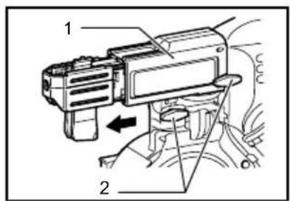
Installing or removing the bit
Loosen the thumb screws which secure the casing. Pull out the casing in the direction of the arrow.
Fig.4
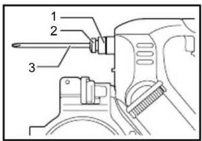
Press the dust cover toward the plane bearing and pull out the bit. If the dust cover cannot be moved as far as the plane bearing, try it again after turning the bit slightly. To install the bit, insert it into the socket while turning it slightly. After installing, always make sure that the bit is securely held in place by trying to pull it out.
Fig.5
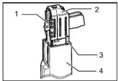
Setting for desired screw length
Fig.6
There are 3 positive-lock screw length settings. To obtain the desired setting, pull out the stopper base while depressing the lever until you see the number of the desired screw length (indicated on the plate) appear to rest on the very top edge of the casing. See the table below for the relation between the number indicated on the plate and the respective screw length ranges.
| Number indicated on the plate | Screw length range |
| 25/28 25 mm - 28 mm | |
| 32 28 mm - 35 mm | |
| 41 35 mm - 41 mm |
009832
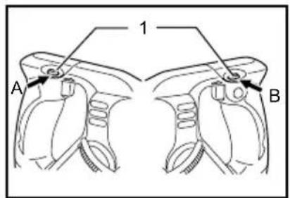
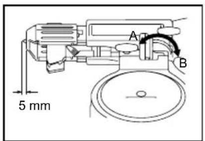
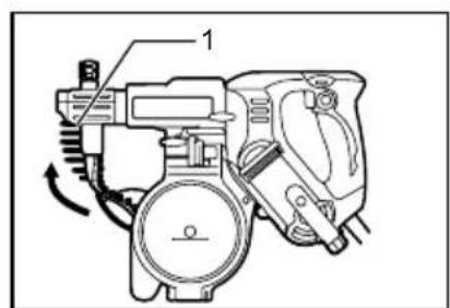
Adjusting the driving depth
Fig.7
Depress the stopper base as far as it will go. While keeping it in this position, turn the adjusting knob until the bit tip projects approx. 5 mm from the stopper base. Drive a trial screw. If the screw head projects above the surface of the workpiece, turn the adjusting knob in the "A" direction; if the screw head is counter-sunk, turn the adjusting knob in the "B" direction.
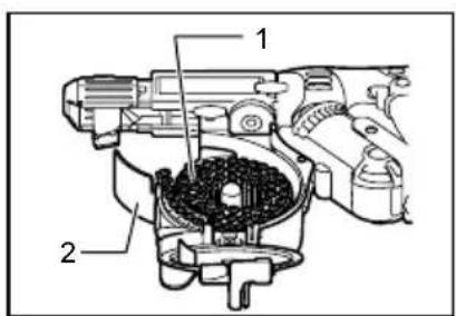
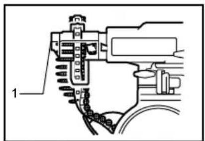
Installing screw strip
- Squeeze the lock lever with fingers and open the magazine cap.
Fig.8
- Roll up the screw strip in a form of coil counterclockwise and place it inside the magazine.
Fig.9
- Run the end of the screw strip on the slotted passage starting from above the magazine.
Fig.10
- Close the magazine cap while squeezing the lock lever with fingers.
Fig.11
- Insert the top end of the screw strip into the portion A of the feeder box and feed it in the direction of the arrow.
Fig.12
- Set the screw strip so that the first screw of the strip seats with a space for one screw left before the screw-driving position.
Fig.13
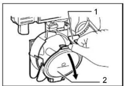
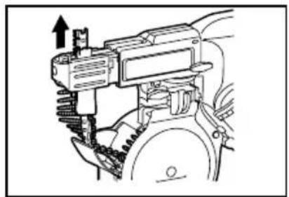
Removing the screw strip
When removing the screw strip at or before using up the screws, pull it out in the direction of the arrow.
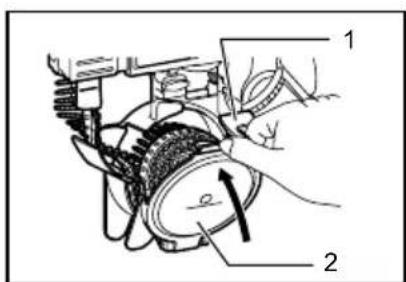
Fig.14
If you set the reverse lever as shown in the figure, you can pull out the screw strip in the reverse direction of the arrow.
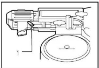
Fig.15
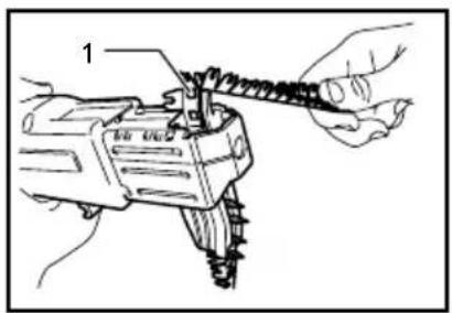
Pulling away the screw strip
Fig.16
While operating the tool with the screw strip, the used strip comes out. as shown in the figure.
Hook a hole in the strip on the protrusion (A) and then pull away the used strip that has come out in the direction of arrow.
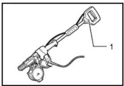
Extension handle (optional accessory)
Fig.17
Use of extension handle allows you to drive screws into floors while standing.
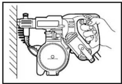
OPERATION
Driving operation
Fig.18
Switch on the tool by pressing the switch trigger and at the same time pushing the lock button. Hold the tool squarely against the workpiece and apply forward pressure to the tool. The screw will be automatically carried to the driving position and driven into the workpiece.
NOTE:
- Do not fire the tool without screws. This will damage the workpiece.
- Do not apply oil or grease on the sliding surface of the feeder box.
MAINTENANCE
CAUTION:
- Always be sure that the tool is switched off and unplugged before attempting to perform inspection or maintenance.
- Never use gasoline, benzine, thinner, alcohol or the like. Discoloration, deformation or cracks may result.
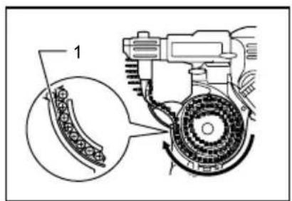
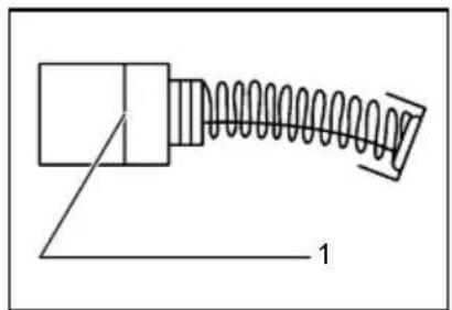
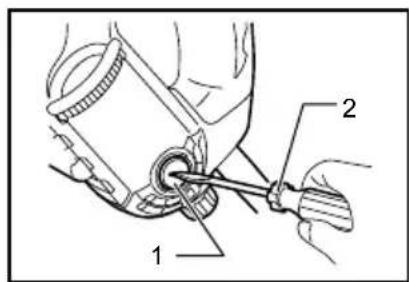
Replacing carbon brushes
Fig.19
Remove and check the carbon brushes regularly. Replace when they wear down to the limit mark. Keep the carbon brushes clean and free to slip in the holders. Both carbon brushes should be replaced at the same time. Use only identical carbon brushes.
Use a screwdriver to remove the brush holder caps. Take out the worn carbon brushes, insert the new ones and secure the brush holder caps.
Fig.20
To maintain product SAFETY and RELIABILITY, repairs, any other maintenance or adjustment should be performed by Makita Authorized Service Centers, always using Makita replacement parts.
OPTIONAL ACCESSORIES
CAUTION:
• These accessories or attachments are recommended for use with your Makita tool specified in this manual. The use of any other accessories or attachments might present a risk of injury to persons. Only use accessory or attachment for its stated purpose.
If you need any assistance for more details regarding these accessories, ask your local Makita Service Center.
- Phillips bit
- Drywall screw strips
- Extension handle
- Plastic carrying case
NOTE:
- Some items in the list may be included in the tool package as standard accessories. They may differ from country to country.
Michigan Drive, Tongwell,
Milton Keynes, Bucks MK15 8JD, Англія
30.1.2009
000230
Tomoyasu Kato
Директор
Makita Corporation
3-11-8, Sumiyoshi-cho,
Anjo, Aichi, 446-8502, ЯПОНІЯ
GEA010-1
Michigan Drive, Tongwell,
Milton Keynes, Bucks MK15 8JD, Anglia
30.1.2009
000230
Tomoyasu Kato
Dyrektor
Makita Corporation
3-11-8, Sumiyoshi-cho,
Anjo, Aichi, 446-8502, JAPONIA
GEA010-1
Michigan Drive, Tongwell,
Milton Keynes, Bucks MK15 8JD, Anglia
30.1.2009

000230
Tomoyasu Kato
Director
Makita Corporation
3-11-8, Sumiyoshi-cho,
Anjo, Aichi, 446-8502, JAPONIA
GEA010-1
Michigan Drive, Tongwell,
Milton Keynes, Bucks MK15 8JD, England
30.1.2009
000230
Tomoyasu Kato
Direktor
Makita Corporation
3-11-8, Sumiyoshi-cho,
Anjo, Aichi, 446-8502, JAPAN
GEA010-1
Michigan Drive, Tongwell,
Milton Keynes, Bucks MK15 8JD, Anglia
30.1.2009
000230
Tomoyasu Kato
Igazgató
Makita Corporation
3-11-8, Sumiyoshi-cho,
Anjo, Aichi, 446-8502, JAPÁN
GEA010-1
Michigan Drive, Tongwell,
Milton Keynes, Bucks MK15 8JD, Anglicko
30.1.2009
000230
Tomoyasu Kato
Riaditel'
Makita Corporation
3-11-8, Sumiyoshi-cho,
Anjo, Aichi, 446-8502, JAPONSKO
GEA010-1
TIETO POKYNY USCHOVAJTE.
⚠️VAROVANIE:
Michigan Drive, Tongwell,
Milton Keynes, Bucks MK15 8JD, England
30.1.2009

000230
Tomoyasu Kato
Ředitel
Makita Corporation
3-11-8, Sumiyoshi-cho,
Anjo, Aichi, 446-8502, JAPAN
GEA010-1
TYTO POKYNY USCHOVEJTE.
⚠️VAROVÁNÍ:
VOLITELNÉ PŘÍSLUŠENSTVÍ
⚠POZOR:
- Intended use
- Power supply
- Noise
- Wear ear protection
- Vibration
- WARNING:
- For European countries only
- EC Declaration of Conformity
- General Power Tool Safety Warnings
- SCREWDRIVER SAFETY WARNINGS
- SAVE THESE INSTRUCTIONS.
- ⚠ WARNING:
- FUNCTIONAL DESCRIPTION
- CAUTION:
- Switch action
- Fig.1
- Reversing switch action
- Fig.2
- Hook
- Fig.3
- ASSEMBLY
- Installing or removing the bit
- Fig.4
- Fig.5
- Setting for desired screw length
- Fig.6
- Adjusting the driving depth
- Fig.7
- Installing screw strip
- Fig.8
- Fig.9
- Fig.10
- Fig.11
- Fig.12
- Fig.13
- Removing the screw strip
- Fig.14
- Fig.15
- Pulling away the screw strip
- Fig.16
- Extension handle (optional accessory)
- Fig.17
- OPERATION
- Driving operation
- Fig.18
- NOTE:
- MAINTENANCE
- Replacing carbon brushes
- Fig.19
- Fig.20
- OPTIONAL ACCESSORIES
- ⚠️VAROVANIE:
- ⚠️VAROVÁNÍ:
- VOLITELNÉ PŘÍSLUŠENSTVÍ
- ⚠POZOR:
Brand : MAKITA
Model : 6841R
Category : Screwdriver