MVHN12AH - Tripod MANFROTTO - Free user manual and instructions
Find the device manual for free MVHN12AH MANFROTTO in PDF.
| Product type | Professional video head |
| Brand | Manfrotto |
| Model | MVHN12AH |
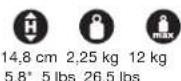
| Weight (with panhandle) | 2.25 kg / 5 lbs |
| Maximum counterbalance load | 12.0 kg / 26.5 lbs (at 55 mm COG) |
| Minimum counterbalance load | 4.0 kg / 8.8 lbs (at 55 mm COG) |
| Center of gravity (COG) offset | 55 mm, 75 mm, 100 mm |
| Operating temperature range | -15°C to +50°C |
| Storage temperature range | -20°C to +60°C |
| Bubble level power supply | CR1220-3V battery |
| Bubble level type | Backlit with low battery indicator |
| Pan movement | 360° with adjustable friction and lock |
| Tilt movement | +90°/-70° with adjustable friction and lock |
| Tripod attachment | 3/8" female thread or 75 mm half-ball adapter (optional) |
| Camera attachment | Sliding quick release plate with interchangeable 1/4" and 3/8" screws |
| Load compensation | Continuously adjustable nitrogen piston system |
| Panhandle | Removable and reversible (left/right handed) with 10° step adjustment |
| Compatible accessories | Manfrotto articulated arm with anti-rotation (3/8" thread) |
| Maintenance | Clean with non-aggressive detergent; PTFE lubrication if necessary |
| Safety | Anti-fall safety button on the plate; do not place hands in the piston area |
| Protection rating | IP5X |
| Warranty | Standard warranty + possible extension to 5 years upon registration |
Frequently Asked Questions - MVHN12AH MANFROTTO
User questions about MVHN12AH MANFROTTO
0 question about this device. Answer the ones you know or ask your own.
Ask a new question about this device
Download the instructions for your Tripod in PDF format for free! Find your manual MVHN12AH - MANFROTTO and take your electronic device back in hand. On this page are published all the documents necessary for the use of your device. MVHN12AH by MANFROTTO.
USER MANUAL MVHN12AH MANFROTTO
natural_image
Technical line drawing of a mechanical device with gears and a lever (no text or symbols)INSTRUCTIONS MVHN12AH
3
natural_image
Technical line drawing of a mechanical surveying instrument with no visible text or symbols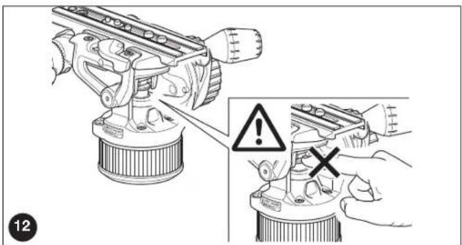
INDEX
GB pag. 8 - 11
I pag. 12 - 15
D pag. 16 - 20
F pag. 21 - 25
E pag. 26 - 29
CN pag. 30 - 32
KO pag. 33 - 36
J pag. 37 - 40
RU pag. 41 - 44
EU DECLARATION OF CONFORMITY.... pag. 45
KOREA CERTIFICATION pag. 46
GB
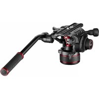
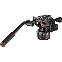
INTRODUCTION
Designed for ENG video cameras and interchangeable lens camcorders or DSLRs from 4 kg (8.8 lbs) to 12 kg (26.5 lbs). Declared at 20°C and 55mm C.o.g.
For any uses other than those intended, in order for proper performance and safety of use to be guaranteed, please contact your reseller or the manufacturer directly via the Contact us section on manfrotto.com.
The product is intended for professional use.
KEY FEATURES
- Quick release sliding plate for balancing the camcorder
- 1/4" camera screw "S" and 3/8" adapter "Z" for all camera types
- 3/8" female tripod attachment or for fixing the half ball adapter
- PAN and TILT drag adjustment
- Pan bar can be fitted either side
- Spirit level (with backlight) for accurate levelling
• Incredibly precise, continuous counterbalance system
TEMPERATURE RANGE
Working Temperatures between -15°C and +50°C.
Storage Temperatures between -20^ and +60^ .
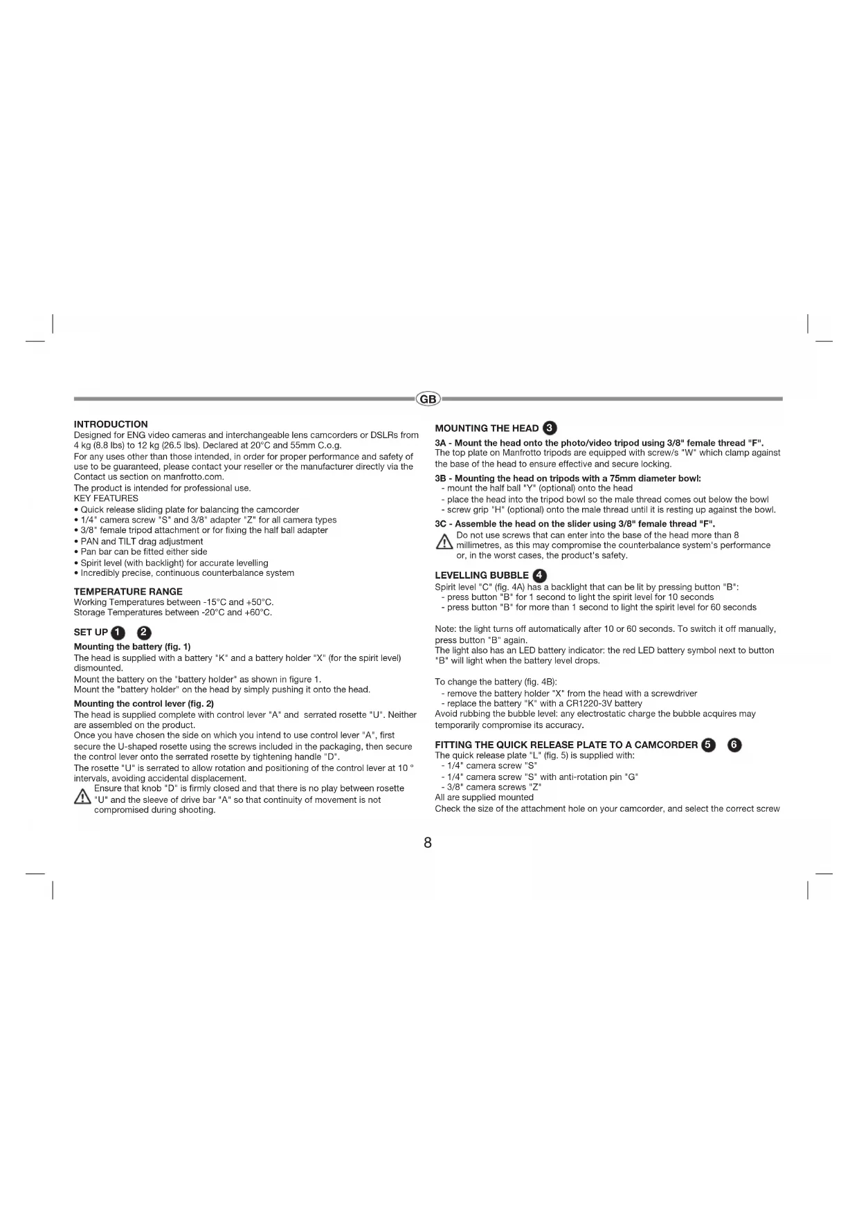
SET UP 1 2
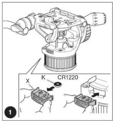
Mounting the battery (fig. 1)
The head is supplied with a battery "K" and a battery holder "X" (for the spirit level) dismounted.
Mount the battery on the "battery holder" as shown in figure 1.
Mount the "battery holder" on the head by simply pushing it onto the head.
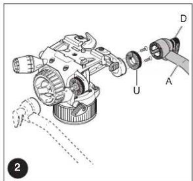
Mounting the control lever (fig. 2)
The head is supplied complete with control lever "A" and serrated rosette "U". Neither are assembled on the product.
Once you have chosen the side on which you intend to use control lever "A", first secure the U-shaped rosette using the screws included in the packaging, then secure the control lever onto the serrated rosette by tightening handle "D".
The rosette "U" is serrated to allow rotation and positioning of the control lever at 10^ intervals, avoiding accidental displacement.
Ensure that knob "D" is firmly closed and that there is no play between rosette "U" and the sleeve of drive bar "A" so that continuity of movement is not compromised during shooting.
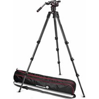
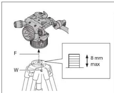
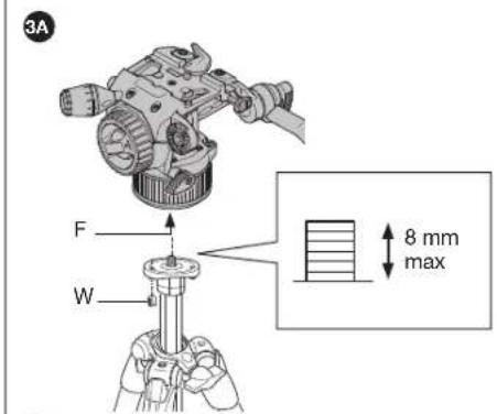
MOUNTING THE HEAD 3
3A - Mount the head onto the photo/video tripod using 3/8" female thread "F". The top plate on Manfrotto tripods are equipped with screw/s "W" which clamp against the base of the head to ensure effective and secure locking.
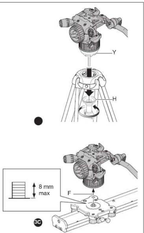
3B - Mounting the head on tripods with a 75mm diameter bowl: - mount the half ball "Y" (optional) onto the head
- place the head into the tripod bowl so the male thread comes out below the bowl - screw grip "H" (optional) onto the male thread until it is resting up against the bowl.
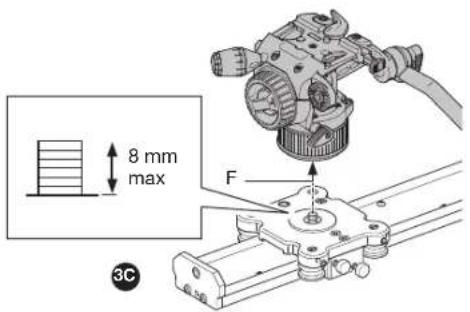
3C - Assemble the head on the slider using 3/8" female thread "F".
Do not use screws that can enter into the base of the head more than 8 millimetres, as this may compromise the counterbalance system's performance or, in the worst cases, the product's safety.
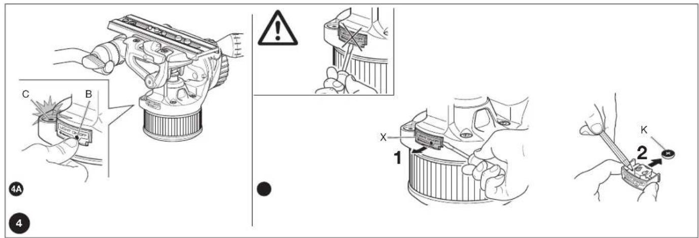
LEVELLING BUBBLE 4
Spirit level "C" (fig. 4A) has a backlight that can be lit by pressing button "B":
- press button "B" for 1 second to light the spirit level for 10 seconds
- press button "B" for more than 1 second to light the spirit level for 60 seconds
Note: the light turns off automatically after 10 or 60 seconds. To switch it off manually, press button "B" again.
The light also has an LED battery indicator: the red LED battery symbol next to button "B" will light when the battery level drops.
To change the battery (fig. 4B):
- remove the battery holder "X" from the head with a screwdriver
- replace the battery "K" with a CR1220-3V battery
Avoid rubbing the bubble level: any electrostatic charge the bubble acquires may temporarily compromise its accuracy.
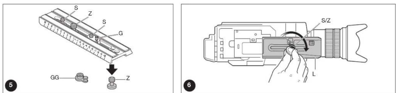
FITTING THE QUICK RELEASE PLATE TO A CAMCORDER 5 6
The quick release plate "L" (fig. 5) is supplied with:
- 1/4" camera screw "S"
- 1/4" camera screw "S" with anti-rotation pin "G"
- 3/8" camera screws "Z"
All are supplied mounted
Check the size of the attachment hole on your camcorder, and select the correct screw
GB
"Z" or "S" to fit to the quick release plate (fig. 5).
To remove the screw not used proceed as follow (fig. 5)
- lightly press the rubber cap "GG" (fig. 1) with your finger
- remove the screw not used
- reposition the cap to prevent the screw from being lost
If the camcorder also has an anti-rotation hole, insert the anti-rotation pin "G" into the plate as shown in figure 5. Align the camera on the plate "L" ensuring the pin "G" is correctly inserted into the camera before fastening the plate.
Fix the camcorder onto the plate "L" (fig. 6) by tightening screw "Z" or "S" into the threaded hole in the camcorder. You can use a coin to tighten the screw, but WITHOUT APPLYING FORCE.
If the camcorder does not have an anti-rotation hole, align the camcorder lens with the arrow marked "LENS" on the underside of camera plate "L" before tightening fully.
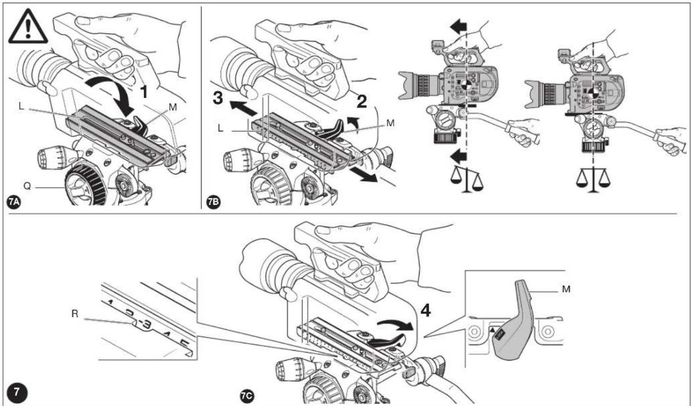
ATTACHING THE CAMCORDER TO THE HEAD 7
Before attaching the camcorder on the head, make sure the tripod is in a stable and secure position and that the legs are locked.
Bring the head to 0^ as in figure 7A (horizontal plate) and lock the tilt movement by means of the brake "Q".
Hold the camcorder and angle it so the plate "L" (fig. 7A) slots into the head, with the long edge furthest from lever "M" dropping in first. Then push down so that the plate drops in fully, and lever "M" clicks shut.
Hold the camera throughout this operation to prevent it from slipping backwards and forwards.
Finding the right balance point for your camcorder:
- Level the head on the tripod using the spirit level "C" (fig. 4).
- Unlock the tilt brake "Q"
- Loosen the lever "M" (fig. 7B) and keep it pressed down as you slide the camcorder until you reach the balance point in which the head remains level under the load of the camcorder.
- With the camcorder at the balance point, lock plate "L" in position by locking knob "M" as shown in figure 7C: the arrow must remain inside the LOCK rectangle.
NOTE:
Once the correct position has been found it can be memorised by taking note of plate "L"'s position on the graded scale "R".
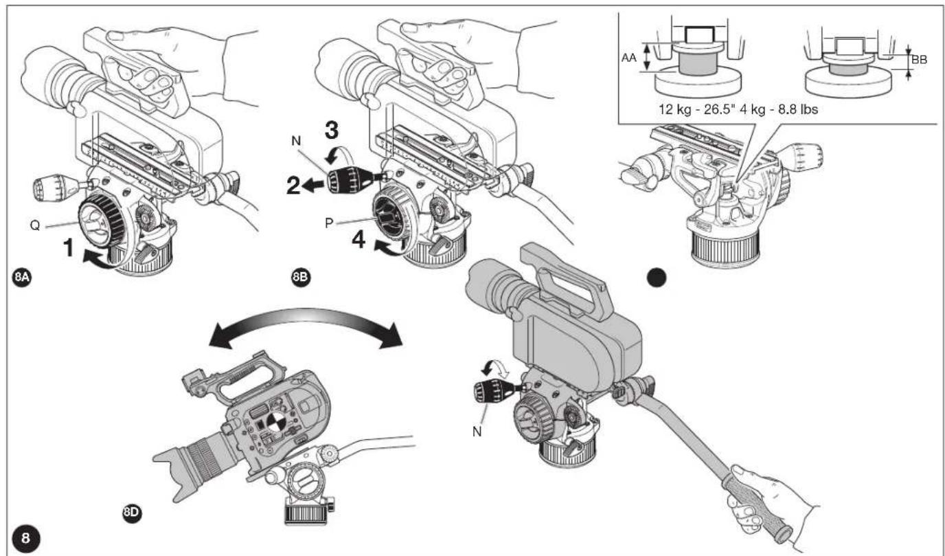
COUNTERBALANCING THE CAMERA ON THE HEAD 8
To balance the weight of your equipment, the head features a nitrogen piston counterbalance system. Please proceed as follows:
- Make sure that you have unlocked the tilt brake "Q"
- Pull out the counterbalance lever "N"
- Turn counter-balance lever "N" counter clockwise until it reaches the end of the counterbalance adjustment system run. The "N" lever modifies the balanced load: it is a control system, not a lock. Once the limit switch positions AA and BB have been reached (see figure 8C) with fluid movement, do not force the lever's rotation. Approximately 8.5 complete rotations of counterbalance lever "N" are required to move from position "BB", equivalent to a counterbalanced load of 4 kg (8.8 lbs) to position "AA", equivalent to a balanced load of 12 kg-26.5 lbs@55 c.o.g.
A higher number of rotations may compromise the counterbalance system's performance or, in the worst cases, the product's safety.
- Turn the tilt drag knob "P" clockwise.
With one hand on the pan bar, tilt the camcorder forwards and backwards: move counter-balance lever "N" (lock/unlock) until the camera is locked into place for each tilt angle.
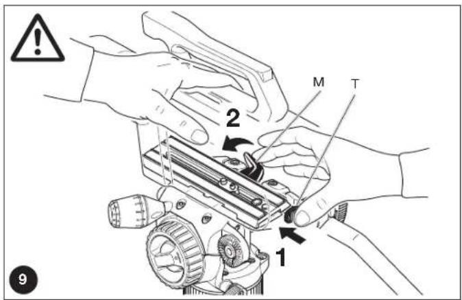
REMOVING THE CAMCORDER FROM THE HEAD 9
Whenever the camcorder needs to be removed from the head, hold the camcorder securely with one hand and press "M" to release the plate and camera with the other hand, while keeping the "T" button pressed down.
The purpose of the "T" Security Button is to ensure that the video camera is not released accidentally.
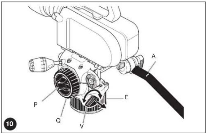
USE 10
For correct use, the head must be adequately levelled.
The head features 360° pan and vertical tilt (+90°/-70°) which are controlled using the pan bar "A" (fig. 10).
- The pan movement can be locked using the knob "V" and has adjustable drag control: friction is increased by turning gear "E".
- The tilt movement can be locked using the knob "Q" and has adjustable drag control: friction is increased by turning gear "P".
Note: The lever angle "V" can be positioned as required without affecting the lock itself.
GB
Pull the lever outwards, turn as required and release: it will be set to the new position.
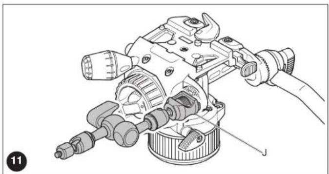
ATTACHING ACCESSORIES 11
The head has one 3/8" female thread "J" with an anti-rotation attachment which can be used to attach accessories such as Manfrotto arms equipped with an anti-rotation system.
Please note: fitting additional accessories may require adjusting the head's balance settings. An excessive load imbalance could compromise the tripod's stability and invalidate the quality of the pan and tilt movements. In the worst cases, it could also compromise product safety.
USAGE ADVICE
Prior to using the product, especially after an extended period of disuse, it is advisable to restore proper lubrication of the gas spring gaskets. This is done by rotating the head 3 times with the "A" lever through the entire TILT travel range.
Before use, please ensure that the central counterbalance system area is free of any components that could affect the device's correct operation (dust, sand, etc.).
Gas piston performance is affected by varying temperatures: to maintain correct counterbalance with high temperature variations, the counterbalance knob must be appropriately adjusted.
STORAGE
The product is NOT SUBJECT TO specific provisions for the carriage of dangerous goods by road (ADR), rail (RID), inland waterway (ADN), sea (IMDG) and air (ICAO/IATA). We recommend transporting the equipment disassembled from the support and mounted on the head.
When not in use, the product must be stored with its PAN & TILT brake and Drag disengaged with the plate holder in a horizontal position.
Storage temperatures must range between -20^ and +60^ .
In case of extended periods of disuse, remove the battery from the light source (fig.4B).
MAINTENANCE
Clean the product only with non-aggressive detergents and soft cloths.
Periodically remove dust and sand from the locking screws and sliding parts. Do not use sharp or metallic tools when carrying out cleaning procedures.
After a long period of disuse, if squeaking sounds are heard in the piston area, the cylinder shaft should be lubricated with a PTFE spray (not included).
CAUTION 12
While the head is moving, do not put your hands or insert tools in the piston area (fig. 12).
Keep the product away from children. Contains detachable parts that could be swallowed.
PRECAUTIONS
- Do not tamper with, modify or disassemble the product or any of its parts to avoid damaging its performance or safety.
- Do not use the product outside the defined scope.
- Using a damaged product, for example, due to accidental knocks or falls, may compromise its operation safety.
- In such cases, contact your reseller or the manufacturer directly via the Contact Us section on manfrotto.com.
- Dry the product after use in damp conditions to avoid corrosion.
- Especially when using the product in the vicinity of a marine environment.
- The product is not designed to be used immersed in liquids.
- Avoid exposing the product to sunshine for long periods or leaving it inside a vehicle, where high temperatures can be reached.
- Do not expose to direct heat sources that may cause temperatures to exceed the maximum temperatures specified in the "Working Temperature" section.
ELECTRICAL PRECAUTION
Never use any battery, power supply or accessory that is not specified by this manual. Only use CR1220-3V batteries.
DISCLAIMER
The information contained in this document is subject to change without notice. When needed, please check for updates to this manual by visiting the Products section on manfrotto.com or by requesting an updated copy in the Contact Us section. Manfrotto assumes no liability whatsoever for any damage that may, directly or indirectly, result to persons, things or animals as a consequence of failure to comply with all the requirements specified in this document, (in particular with regard to product installation, use and maintenance), as well as injury and damage deriving from incorrect use or purposes that go beyond the normal operating conditions and restrictions.
Any changes or modifications to the product not expressly approved by Manfrotto shall automatically result in the exclusion of Manfrotto's liability.
GB
INFORMATION FOR USERS

In accordance with Article 10 of Directive 2012/19/UE of the 04/07/2012 concerning Waste Electrical and Electronic Equipment (WEEE).
The above symbol, also present on equipment, indicates that, at such time as the user should decide to dispose of the equipment, it must NOT be disposed of as unsorted municipal waste, but must be collected separately. The same applies to all components of the equipment and any recharge or refill elements that the product may comprise.
For information on the waste collection systems suitable for this equipment, contact the seller or any authorised member of the National Registers in EU countries. Household (or similar) waste may be disposed of via standard municipal differentiated waste collection schemes.
If you purchase a new version of this model or similar equipment - or if your existing equipment measures less than 25 cm - you may return the items you no longer require to your retailer who will take care of contacting the company or organization handling the proper collection and management of used equipment.
Correct separate collection and specific treatment of WEEE are necessary to avoid potential damage to human health and the environment, and favour the recycling and recovery of component materials.
Improper or illegal disposal of this product by the user will result in punishments or fines being applied in accordance with national Decrees based on Directive 91/156/EC and 2008/98/EC.
DECLARATION REGARDING PRESSURE RISK ASSESSMENT
The Nitrotech series heads include a gas spring used in their counterbalance system. This component is designed and built following a high-quality engineering procedure; it complies with European PED Directive 2014/68/EU Article 4, paragraph 3 and is not subject to CE marking.
TECHNICAL PRODUCT SHEET
Counterbalanced Weight:
| C.O.G. Min. Max. | ||
| 55 mm 4,0 kg/8,8 | lbs 12,0 kg/26,5 lbs | |
| 75 mm 3,4 kg/7,5 | lbs 9,5 kg/20,9 lbs | |
| 100 mm 2,9 kg/6,4 | lbs 8,6 kg/19,0 lbs |
Max Gas Pressure: 135bar@20°C
Illuminated Bubble Battery: NO. CR1220-3V
Degree of product protection: IP5X
Weight produced with drive lever: 2,25 kg / 5 lbs
Thank you for purchasing a Manfrotto product.
Manfrotto products are warranted to be fit for the purpose for which they have been designed, and to be free from defects in materials and workmanship. This guarantee does not cover the product against subsequent damage or misuse. The period of validity of the Standard Limited Warranty is defined by the law in force in the country, state or region where the product is sold. Please retain your receipt as proof of purchase to repair your product under warranty.
How to get an extra warranty coverage
Beyond the standard compulsory coverage outlined above, this product is eligible for a warranty extension valid up to 5 years from the date of purchase. The Limited Conventional Warranty Extension does not affect the standard compulsory coverage. To take advantage of the warranty extension scheme, you must register your purchase at www.manfrotto.com/warranty.
I
INTRODUZIONE
ATTACCHI PER ACCESSORI 11
WESENTLICHE FEATURES
Compliance for USA and Canada
FCC Class B Information
This equipment has been tested and found to comply with the limits for a Class B digital device, pursuant to part 15 of the FCC Rules. These limits are designed to provide reasonable protection against harmful interference in a residential installation. This equipment generates, uses and can radiate radio frequency energy and, if not installed and used in accordance with the instructions, may cause harmful interference to radio communications. However, there is no guarantee that interference will not occur in a particular installation.
If this equipment does cause harmful interference to radio or television reception, which can be determined by turning the equipment off and on, the user is encouraged to try to correct the interference by one or more of the following measures: Reorient or relocate the receiving antenna.
Increase the separation between the equipment and receiver. Connect the equipment into an outlet on a circuit different from that to which the receiver is connected.
Consult the dealer or an experienced radio/TV technician for help.
ICES-003/NMB-003 Statement
CONTENT OF EU DECLARATION OF CONFORMITY
Manufacturer's name : Lino Manfrotto + Co. S.p.A.
Manufacture's address : Via Valsugana 100, 36022 Cassola (VI), Italy
Product name : PROFESSIONAL FLUID VIDEO HEAD
Product code : MVHN12AH
GB - Complies with the requirements of the following directives and carries "CE" marking accordingly :
GB - The product complies with Directive 2011/65/EU of the European Parliament and of the Council of 8 June 2011 on the restriction of the use of certain hazardous substances in electrical and electronic equipment.
Class B Equipment (For Home Use Broadcasting & Communication Equipment)
This equipment is home use (Class B) electromagnetic wave suitability equipment and
to be used mainly at home and it can be used in all areas.

기기명칭:PROFESSIONAL FLUID VIDEO HEAD
모 델 명:MVHN8AH
After sales service:
VITEC GROUP ITALIA SPA
KOREA Liaison Office
Fl. 41st, #152 Teheran-ro,
Gangnam-gu, Seoul, Korea
Phone no.: (029) 20084949
Cod. 1094597 - 10/17 Copyright © 2017 Manfrotto Bassano Italy