GW12797 - Electric actuator Gewiss - Free user manual and instructions
Find the device manual for free GW12797 Gewiss in PDF.

| Product Type | Electric actuator for shutters, blinds, and awnings |
| Brand | Gewiss |
| Model | GW12797 |
| Dimensions (approx.) | 2 Chorus modules (width 36 mm, height 90 mm, depth 64 mm) |
| Weight (approx.) | 150 g |
| Power Supply | KNX Bus, 29 V DC SELV |
| Bus Consumption | 8 mA max |
| Number of Channels | 1 channel |
| Output Type | 2 NO relays (8 A, 250 V~) for up and down, interlocked |
| Max Current per Output | 6 A for motors (per EN60669-2-1), 8 A for resistive load |
| Main Functions | Up/down/stop command, slat adjustment, relative position, scenarios (8), priority commands, alarms, lock, status information |
| Control Elements | 1 physical address programming button, 2 local control buttons |
| Display | 1 red LED (programming), 2 green LEDs (output status), 2 amber LEDs (nighttime localization) |
| Configuration | ETS software |
| Bus Connection | 2-pin plug connector ∅ 1 mm |
| Electrical Connections | Screw terminals, max. cross-section 4 mm² |
| Operating Temperature | -5 to +45 °C |
| Storage Temperature | -25 to +70 °C |
| Relative Humidity | 93% max (non-condensing) |
| Protection Rating | IP20 |
| Maintenance and Cleaning | No special maintenance. Clean with a soft, dry cloth. |
| Safety | Installation by qualified personnel in accordance with applicable standards and the KNX Technical Manual. |
| Spare Parts and Reparability | Device not user-repairable. No spare parts available. |
| Standards | Directives 2006/95/EC, 2004/108/EC, EN50428, EN50090-2-2, KNX certification |
Frequently Asked Questions - GW12797 Gewiss
User questions about GW12797 Gewiss
0 question about this device. Answer the ones you know or ask your own.
Ask a new question about this device
Download the instructions for your Electric actuator in PDF format for free! Find your manual GW12797 - Gewiss and take your electronic device back in hand. On this page are published all the documents necessary for the use of your device. GW12797 by Gewiss.
USER MANUAL GW12797 Gewiss
natural_image
Close-up of a metallic electronic device with two square buttons and a 'KNX E13' logo (no readable text or symbols beyond branding)GW 10 797 GW 12 797 GW 14 797
flowchart
graph TD
    A["Block 1"] --> B["Block 2"]
    C["Block 3"] --> D["Block 4"]
    style A fill:#f9f,stroke:#333
    style C fill:#f9f,stroke:#333
    style B fill:#ccf,stroke:#333
    style D fill:#ccf,stroke:#333
text_image
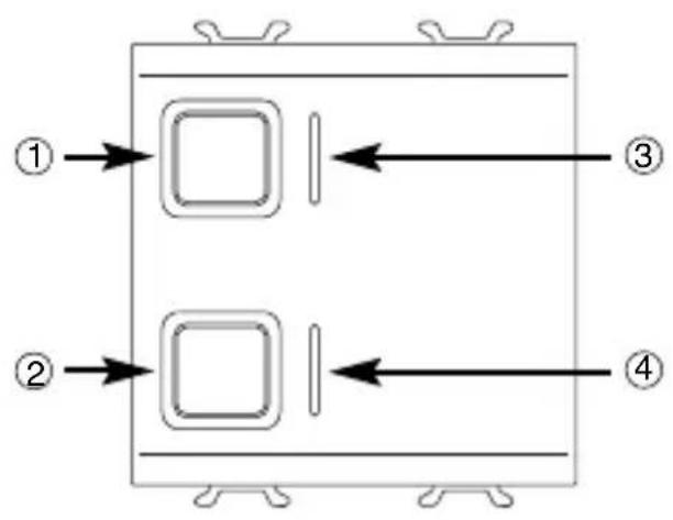
Technical diagram of an electronic device with numbered components and directional arrows indicating flow or movement.① Pulsante comando locale 1 (SU) - Local command button 1 (UP) - Bouton de commande locale 1 (HAUT) - Pulsador mando local 1 (SUBIR) - Taste lokale Steuerung 1 (AUF)
② Pulsante comando locale 2 (GIÙ) - Local command button 2 (DOWN) - Bouton de commande locale 2 (BAS) - Pulsador mando local 2 (BAJAR) - Taste lokale Steuerung 2 (AB)
③ LED stato uscita SU e localizzazione notturna - LED output status UP and night -time location - LED d'état sortie HAUT et de localisation nocturne - LED estado salida SUBIR y localización nocturna - LED für Status Ausgang AUF und Nachtanzeige
④ LED stato uscita GIÙ e localizzazione notturna - LED output status DOWN and night -time location - LED d'état sortie BAS et de localisation nocturne - LED estado salida BAJAR y localización nocturna - LED für Status Ausgang AB und Nachtanzeige
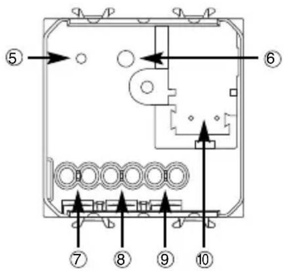
⑤ LED di programmazione indirizzo fisico - Physical address programming LED - LED de programmation adresse physique - LED de programación dirección física - LED für Programmierung physikalische Adresse
⑥ Tasto di programmazione indirizzo fisico - Physical address programming button - Touche de programmation adresse physique - Tecla de programación dirección física - Taste für Programmierung physikalische Adresse
⑦ Uscita relè (GIÙ) - Output relay (DOWN) - Sortie relais (BAS) - Salida relé (BAJAR) - 7 Ausgang Relais (AB)
⑧ Uscita relè (SU) - Output relay (UP) - Sortie relais (HAUT) - Salida relé (SUBIR) - Ausgang Relais (AUF)
⑨ Comune - Common - Commun - Común - Allgemein
10 Terminali bus - Bus terminals - Borniers bus - Terminales bus - Busanschlüsse
INDICE
text_image
bus + GIÚ SU M N L COMINSTALLAZIONE
natural_image
Mechanical assembly diagram showing a component being inserted into a housing (no text or symbols visible)
text_image
Technical diagram of a mechanical device with numbered components and directional arrows indicating assembly or movement.INSTALLAZIONE
Connessione carichi

natural_image
Technical illustration of a mechanical assembly with multiple circular components and a tool (no text or symbols visible)
Completamento
PROGRAMMING WITH ETS SOFTWARE.... 16
TECHNICAL DATA 17
GENERAL DESCRIPTION
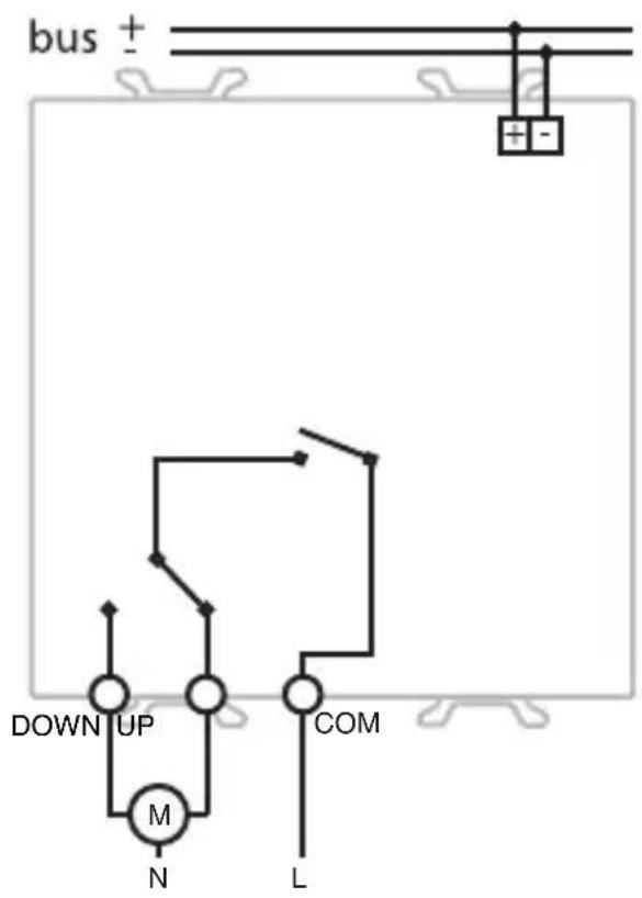
The 1 channel 6A KNX motor command actuator controls the movement of motorised shutters, curtains and blinds. 2 output relays, one for UP and one for DOWN movements, are interlocked to avoid damage to the connected motor.
The movement commands can be accessed through Building Automation control or sensor devices using the KNX bus, or they can be generated locally using the front buttons.
The actuator is powered by the bus line and is fitted with 4 front LEDs: 2 green LEDs to indicate that the shutters are moving (up/down) and 2 amber LEDs for night localisation.
Functions
The actuator is configured by the ETS software to achieve one of the functions listed below.
Control functions
- up/down/stop movement control
- lath regulation
- movement command to relative position (0%-100%)
- automatic regulation of the lath position
Scenes:
- memorising and activation of 8 scenes (value 0-63)
- enabling/disabling memorising of scenes via bus
Priority controls:
- setting of the position at the end of the forced command
Block command:
- Setting of the position at the end of the block command
Alarms:
- management of alarm positions (up to 3 sensors) and periodic monitoring of input objects
Status information:
- sending to bus with settable parameters
- information on last performed movement
- position indication (0%-100%)
Other functions:
- output behaviour setting during bus blackout/reinstatement
GENERAL DESCRIPTION
Connection diagram
text_image
bus + DOWN UP M N L COMINSTALLATION

WARNING: only qualified personnel are permitted to install this device, according to the regulations in force and guide lines provided for KNX installation in the Technical Manual.
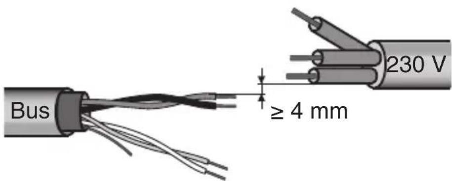
Electrical connections
Minimum bus distance - electrical power line
text_image
Bus ≥ 4 mm 230 VSlot in terminal fixing
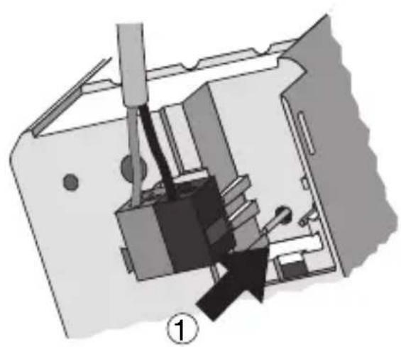
natural_image
Mechanical assembly diagram showing a tool inserted into a device housing (no text or symbols visible)
text_image
Technical diagram of a mechanical device with numbered components and directional arrows indicating movement or assembly.INSTALLATION
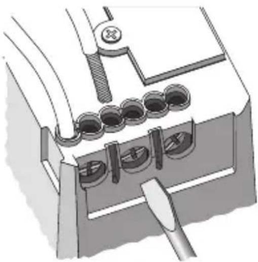
Loads connection
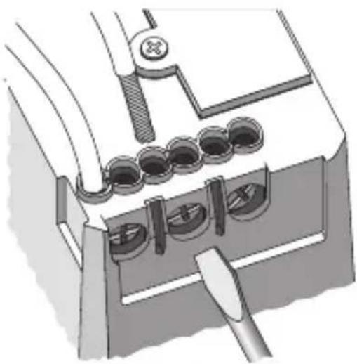
natural_image
Technical illustration of a mechanical assembly with multiple circular components and a tool (no text or symbols visible)Completing installation
Insert the devices into a Chorus support, making sure the two local command buttons are on the left.
Complete the installation with other Chorus devices or hole covers and fix it to the relative container (flush-mounted box, wall-mounted box etc).
Apply the finish plate.
PROGRAMMING WITH ETS SOFTWARE
This device must be configured using the ETS software.
Detailed information on the configuration parameters and their values can be found in the Technical Manual.
TECHNICAL DATA
Communication KNX Bus
Power Supply By KNX Bus, 29 V dc SELV
Bus cable KNX TP1
Bus current consumption 8 mA max
Control elements 1 mini physical address programming key,
2 relay local command buttons
Display elements 1 red physical address programming LED,
2 green output status indicator LEDs,
2 amber LED for night localisation
Actuator elements 1 single-pole relay with phase branch circuit
1 single-pole relay with exchange contact and
phase branch circuit
Output contact 2 NO 8 A (cosφ=1) - 250 V ac
Max current per load type Motors and reduction units: 6A according to EN60669-2-1
Resistive load: 8 A
Ambit of use Indoors, dry places
Operating temperature -5 ÷ +45 °C
Storage temperature -25 ÷ +70 °C
Relative humidity Max 93% (no condensation)
Bus connection Slot in terminal, 2 pin ∅ 1 mm
Electrical connections Screw terminals, Max cable width: 4 mm ^2
Protection rating IP20
Dimensions 2 Chorus modules
Reference standards Low Voltage Standard 2006/95/EC
Electromagnetic Compatibility Standard 2004/108/EC
EN50428, EN50090-2-2
Certifications KNX
SOMMAIRE
DESCRIPTION GENERALE 20
INSTALLATION 22
PROGRAMMATION AVEC LOGICIEL ETS 24
natural_image
Mechanical assembly diagram showing a tool inserted into a device with a black arrow indicating direction (no text or symbols present)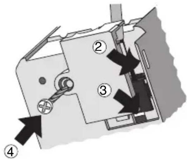
text_image
Technical diagram of a mechanical device with numbered components and directional arrows indicating movement or assembly.INSTALLATION
Connexion charges
natural_image
Technical illustration of a mechanical assembly with clamps and a tool (no text or symbols)Achèvement
PROGRAMMATION AVEC LOGICIEL ETS
Communication Bus KNX
text_image
bus + BAJARSUBIR M N COM LINSTALACIÓN

natural_image
Mechanical assembly diagram showing a component being inserted into a housing (no text or symbols visible)
text_image
Technical diagram of a mechanical device with numbered components and directional arrows indicating movement or assembly.INSTALACIÓN
Conexión cargas

natural_image
Technical illustration of a mechanical assembly with multiple circular components and a tool (no text or symbols visible)Finalización
text_image
bus + ABAUF M N COM LINSTALLATION

natural_image
Mechanical assembly diagram showing a component being inserted into a housing (no text or symbols visible)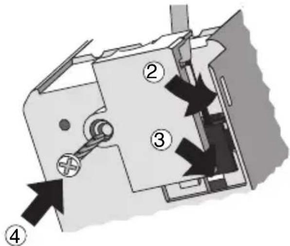
text_image
Technical diagram of a mechanical device with numbered components and directional arrows indicating movement or assembly.INSTALLATION
natural_image
Technical illustration of a mechanical assembly with multiple circular components and a tool (no text or symbols visible)
Vervollständigung
According to article 9 paragraph 2 of the European Directive 2004/108/EC and to article R2 paragraph 6 of the Decision 768/2008/EC, the responsible for placing the apparatus on the Community market is:
GEWISS S.p.A Via A. Volta, 1 - 24069 Cenate Sotto (BG) Italy Tel: +39 035 946 111 Fax: +39 035 945 270 E-mail: qualitymarks@gewiss.com


+39 035 946 111
8.30 - 12.30 / 14.00 - 18.00 lunedì ÷ venerdì - monday ÷ friday
+39 035 946 260