
GW14766 - Electric actuator Gewiss - Free user manual and instructions
Find the device manual for free GW14766 Gewiss in PDF.
| Product type | 1-channel 16 A Easy actuator - flush-mounted |
| Brand | Gewiss |
| Model | GW14766 |
| Dimensions | 2 Chorus modules (width ~36 mm) |
| Weight | Not specified |
| Power supply | KNX/EIB bus (24 Vdc, 5 mA max) |
| Contact type | 1 NO/NC (16 A AC1, 10 A AC15, 250 V~) |
| Main functions | On/off, timer, scenes, priority control |
| Local control | 1 front button for cyclic On/Off switching |
| Visual indicators | 1 red LED (programming), 1 green LED (output status) |
| Operating temperature | -5 °C to +45 °C |
| Storage temperature | -25 °C to +70 °C |
| Relative humidity | Max 93% (non-condensing) |
| Protection degree | IP20 |
| Bus connection | 2-pin plug terminal Ø 1 mm |
| Electrical connections | Screw terminals, max cross-section 2.5 mm² |
| Standards | Low Voltage Directive 2006/95/EC, EMC, IEC 64-8 |
| Maintenance | Clean with a dry cloth, no special maintenance required |
| Safety | Installation by qualified personnel, compliance with IEC 64-8 |
| Spare parts and repairability | Not specified by the manufacturer |
Frequently Asked Questions - GW14766 Gewiss
User questions about GW14766 Gewiss
0 question about this device. Answer the ones you know or ask your own.
Ask a new question about this device
Download the instructions for your Electric actuator in PDF format for free! Find your manual GW14766 - Gewiss and take your electronic device back in hand. On this page are published all the documents necessary for the use of your device. GW14766 by Gewiss.
USER MANUAL GW14766 Gewiss
Warning! The safety of this appliance is only guaranteed if all the instructions given here are followed scrupulously. These should be read thoroughly and kept in a safe place. The Chorus products must be installed in compliance with the requisites of standard CEI 64-8 for devices for domestic use and similar, in non-dusty atmospheres and where special protection against water penetration is not required.
The GEWISS sales organisation is at your disposal for clarifications and technical information.
Gewiss SpA reserves the right to make changes to the product described in this manual at any time and without giving any notice
Pack content
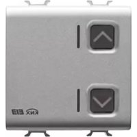
n. 1 channel 16 A Easy actuator - flush-mounted
n. 1 Bus terminal
n. 1 Cover with screw
n. 1 Installation and user manual
Summary
The 1 channel 16 A Easy Actuator - flush-mounted, allows you to activate/deactivate 1 electrical charge using 1 16 A relay fitted with 1 output exchange contact (1 NO/NC). The relay switching command can be given by Home Automation control or sensor devices using the KNX/EIB bus, or they can be generated locally using the front button. The actuator is powered by the bus line and is fitted with a green LED which indicates the output status. This device sends to the bus information on the relay status (ON = NO contact closed, 0FF = NO contact open) at the ignition, at the reception of a command and when it is commanded via the local button.
The actuator foresees the ON/OFF command for the load, the execution of timer commands, scene management and the implementation of priority controls to override the output status.
The various operating methods can be used simultaneously.
This means, for instance, that the device can turn a light on or off, or turn it on or off automatically after a set time has elapsed according to the command received.
The device is fitted inside a standard flush-mounted box, mounted on Chorus supports in the space of two modules.
Functions
The actuator can be configured with the Easy controller to perform one of the following functions:
ACTIVATING AND DEACTIVATING CHARGES
The actuator channel activates or deactivates the electric charge when it receives ON/OFF commands sent, for example, by a contacts interface or a button pad configured in ON/OFF Cyclic switching or Edge management mode.
The green LED comes on to indicate that the relay contact is closed.
GENERAL DESCRIPTION
TIMER COMMANDS
The actuator activates the connected electric charge for the time determined by the Time parameter activation and deactivates when it elapses. This is the setting for the staircase light, for example. If the dimmer actuator receives another Timed ON command during the activation time, the time count restarts from the beginning.
The relay is deactivated and the counter is reset when it receives an OFF command or a scene is activated which includes the OFF command by the actuator.
The Prewarning Time parameter can enable the switch off warning signal: in this case the relay opens briefly (the light goes off for a second) when the time set on the parameter remains before the timer is due to switch off. If necessary it will be possible to send another Timed ON command before the light switches off.
The green LED comes on when the NO relay contact is closed.
PERFORMING PRIORITY CONTROLS
The actuator switches the relay to the ON or OFF status transmitted by the device which sends the priority control.
Until it receives a command cancelling the forcing, the actuator ignores all other commands received including those from the front buttons.
If no other commands are received, at the end of forcing the actuator returns to the condition before its actuation. Otherwise the status remains that of the last command received during override.
The green LED comes on when the NO relay contact is closed.
SCENE MANAGEMENT
The actuator is able to memorize and perform up to 8 scenes; each one has an ON or OFF relay status. It is not possible to associate a timed activation to a scene.
Before memorizing a scene it is necessary to set the desired output status (ON/OFF) for the actuator, for instance using the local button.
The green LED comes on when the NO relay contact is closed.

WARNING: the installation of the device must be exclusively done by qualified personnel, following the regulations in force and the guidelines for KNX/EIB installations.
Warnings for KNX/EIB installations
- The length of the bus line between the 1 channel 16 A Easy actuator and the power supply unit must not exceed 350 metres.
- The length of the bus line between the 1 channel 16 A Easy actuator and the most distant KNX/EIB device must not exceed 700 metres.
- If possible do not create ring circuits so as to prevent undesirable signals and overloads.
- Keep a distance of at least 4mm between the individually insulated cables of the bus line and those of the electric line (figure C).
- Do not damage the electrical continuity conductor of the shielding (figure D).
WARNING: the unused bus signal cables and the electrical continuity conductor must never touch elements under power or the earth conductor!
Electrical connections
WARNING: cut off mains power before connecting the device to the electricity mains!
Figure B shows the electrical connections diagram.
- Connect the bus cable's red wire to the terminal's red connector (+) and the black wire to the black connector (-). Up to 4 bus lines (wires of the same colour in the same connector) can be connected to the terminal (figure E).
- Insulate the screen, the electrical continuity conductor and the remaining white and yellow wires of the bus cable (should a bus cable with 4 conductors be used), which are not needed (figure D).
- Insert the bus connector into the special feet of the device. The fastener guides determine the direction it should be inserted. Insulate the bus terminal using the relative cover, which must be screwed onto the device. The cover guarantees that the power cables and the bus cables are separated by at least 4mm (figure F).
- Connect the charges to the relative screw terminals on the back of the actuator (Figure G), checking that they do not exceed the current limits indicated in the Technical Specifications.
Initialization with the Easy base unit
- Power up the device through the bus.
-
Have the system acquire the device with one of the following procedures:
-
Automatic acquisition (the device still has the factory settings):
-
select the "Application New function" or "Application Edit function" menu in the Easy base unit: the device will be recognized automatically.
-
Manual acquisition (the factory settings have been modified):
-
select the "Application Search device" menu in the Easy base unit;
- briefly press (< 2 seconds) the programming key. The programming LED will light up during the acquisition process (figure A).
The device acquired by the Easy base unit will be listed, with the number assigned, in the channels of the "Application New function" or "Application Edit function" menus.
Initialization with the Easy Controller
- Power up the device through the bus.
- Have the system acquire the device with one of the following procedures:
Automatic acquisition:
-
select the "Search/Config." or "Scan Range" command in the "System" menu;
-
Manual acquisition:
-
select the "Add device" menu in the "System" menu;
- briefly press (< 2 seconds) the programming key. The programming LED will light up during the acquisition process (figure A).
The device acquired is listed with a number allocated, product code and a list of the channels in the "Devices" view.
Completing installation
Insert the devices into a Chorus support, making sure the local command button is at the top.
Complete the installation with other Chorus devices or hole covers and fix it to the relative container (flush-mounted box, wall-mounted box etc). Apply the finish plate.
PROGRAMMING WITH THE EASY CONTROLLER
Programming the actuator through the Easy base unit (code GW 90 831) or with Easy Controller (GW 90 837 / GW 90 838 / GW 90 840).
The actuator channel to be used in the function that is to be created can be selected at choice:
- by pressing the local command button: the corresponding channel will be highlighted in the channel list;
- directly from the list of channels.
The functions can be created after the devices have been selected.
| Names of the functions | |
| buttons Load activation or | deactivation |
| edges Load activation or | deactivation |
| timer mode Load activation | with timer |
| priority control Activation | of priority controls |
| scene Activation of the scenes | |
Refer to the Easy base unit or the Easy Controller documentation for further information on the programming procedures.
Configuration parameters (Easy)
After creating the required function the actuator's operating parameters can be set. The parameters available, in relation to the function created, are listed in the following table.
The underlined value is the default value.
| Function: timer mode | |
| Parameter: activation time | |
| not active no timing | |
| 1 second relay activated for 1 second | |
| 2 seconds relay activated for 2 seconds | |
| 3 seconds relay activated for 3 seconds | |
| 5 seconds relay activated for 5 seconds | |
| 10 seconds relay activated for 10 seconds | |
| 15 seconds relay activated for 15 seconds | |
| 20 seconds relay activated for 20 seconds | |
| 30 seconds relay activated for 30 seconds | |
| 45 seconds relay activated for 45 seconds | |
| 1 minute relay activated for 1 minute | |
| 1.25 minutes relay activated for 75 seconds | |
| 1.5 minutes relay activated for 1.5 minutes | |
| 2 minutes relay activated for 2 minutes | |
| 2.5 minutes relay activated for 2.5 minutes | |
| 3 minutes relay activated for 3 minutes | |
| 5 minutes relay activated for 5 minutes | |
| 15 minutes relay activated for 15 minutes | |
| 20 minutes relay activated for 20 minutes | |
| 30 minutes relay activated for 30 minutes | |
| 1 hour relay activated for 1 hour | |
| 2 hours relay activated for 2 hours | |
| 3 hours relay activated for 3 hours | |
| 5 hours relay activated for 5 hours | |
| 12 hours relay activated for 12 hours | |
| 24 hours relay activated for 24 hours | |
PROGRAMMING WITH THE EASY CONTROLLER
| Function: timer mode | |
| Parameter: prewarning time | |
| no warning no warning15 seconds warning 30 seconds before the relay is deactivated30 seconds warning 15 seconds before the relay is deactivated1 minute warning 1 minute before the relay is deactivated |
Using the local command button
The local command button (figure A) is used to perform the ON/OFF cyclical switching, inverting the relay status each time they are pressed.
If the actuator can be commanded in timer mode by at least one KNX/EIB device then also the local command button will send a timed command.
Local commands are not executed if a priority control is active.

WARNING: the local command buttons are enabled only when the BUS power is available.

Behaviour on the failure and reinstatement of the bus power supply
If the power to the bus decreases below 18V dc for over 1.5 ms the relay switches to OFF (NA contact open, NC contact closed).
When the power is reinstated on the bus, the relay remains in OFF mode.

Maintenance
This device requires no maintenance. Use a dry cloth for possible cleaning.
TECHNICAL DATA
Communication Bus KNX/EIB
Power Supply By KNX/EIB, 29 V dc SELV bus
Bus cable KNX/EIB TP1
Bus current consumption 5 mA max
Control elements 1 mini programming key
1 relay local command button
Display elements 1 red programming LED
1 green output status signal LED
Actuator elements 1 NO/NC 16 A relays with potential free contact
Output contact 1 NO/NC 16 A (AC1) / 10 A (AC15)
Max current per load type Resistive load: 16 A
Incandescent lamp: 10 A
Uncompensated fluorescent lamps: 4 A
Fluorescent lamps with electronic transformers: 4 A
Not suitable for compensated fluorescent lamps and discharge lamps;
please use an auxiliary relay to control such lamps
Motors and reduction units: 10 A
Ambit of use Indoors, dry places
Operating temperature -5 ÷ +45 °C
Storage temperature -25 ÷ +70 °C
Relative humidity Max 93% (no condensation)
Bus connection 2-pin 1 mm plug connector
Electrical connections Screw terminals, Max cable width: 2.5mm^2
Protection rating IP20
Dimensions 2 Chorus modules
Reference standards Low Voltage Directive 2006/95/EC
Electromagnetic Compatibility Directive 2004/108/CE
EN50428, EN50090-2-2
Certification KNX/EIB
SOMMAIRE
page AVERTISSEMENTS GENERAUX 28
DESCRIPTION GENERALE 29
INSTALLATION 31
PROGRAMMATION AVEC EASY CONTROLLER 33
EN SERVICE 36
DONNEES TECHNIQUES 37
AVERTISSEMENTS GENERAUX
Communication Bus KNX/EIB
Alimentation Avec bus KNX/EIB, 29 V cc SELV
Cable bus KNX/EIB TP1
2004/108/CE EN50428, EN50090-2-2
Certifications KNX/EIB
INDICE
pag.
ADVERTENCIAS GENERALES 40
DESCRIPCION GENERAL 41
INSTALACION 43
PROGRAMACION CON EASY CONTROLLER 45
EN SERVICIO 48
DATOS TECNICOS 49
Cable bus KNX/EIB TP1
2004/108/CE EN50428, EN50090-2-2
According to article 9 paragraph 2 of the European Directive 2004/108/EC and to article R2 paragraph 6 of the Decision 768/2008/EC, the responsible for placing the apparatus on the Community market is:
Gewiss S.p.A Via A. Volta, 1-24069 Cenate Sotto (BG) Italy Tel: +39 035 946 111 Fax: +39 035 945 270 E-mail: qualitymarks@gewiss.com


+39 035 946 111
8.30 - 12.30 / 14.00 - 18.00
lunedi ÷ venerdi - monday ÷ friday

+39 035 946 260


- Pack content
- Summary
- Functions
- ACTIVATING AND DEACTIVATING CHARGES
- GENERAL DESCRIPTION
- TIMER COMMANDS
- PERFORMING PRIORITY CONTROLS
- SCENE MANAGEMENT
- Warnings for KNX/EIB installations
- Electrical connections
- Initialization with the Easy base unit
- Initialization with the Easy Controller
- Completing installation
- PROGRAMMING WITH THE EASY CONTROLLER
- Configuration parameters (Easy)
- Using the local command button
- Behaviour on the failure and reinstatement of the bus power supply
- Maintenance
- TECHNICAL DATA
- SOMMAIRE
- AVERTISSEMENTS GENERAUX
- INDICE
Brand : Gewiss
Model : GW14766
Category : Electric actuator