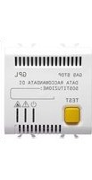
GW20868 - Gas detector Gewiss - Free user manual and instructions
Find the device manual for free GW20868 Gewiss in PDF.


| Product Type | Gas Detector (Methane/LPG) |
| Brand | Gewiss |
| Model | GW20868 |
| Power Supply | 230 V AC / 50 Hz (mains adapter included) |
| Power Consumption | < 2 W standby, < 5 W alarm |
| Dimensions (L × H × D) | 80 × 80 × 35 mm |
| Weight | 120 g (without adapter) |
| Detected Gas Type | Natural gas (methane) and LPG (propane/butane) |
| Alarm Threshold | 10 % LEL (lower explosive limit) |
| Alarm Sound Level | > 85 dB at 1 meter |
| Detection Principle | Semiconductor or catalytic sensor |
| Sensor Lifespan | Approximately 5 years |
| Operating Temperature | -10 °C to +40 °C |
| Operating Humidity | 0 to 95 % RH (non-condensing) |
| Protection Rating | IP20 |
| Mounting | Wall-mounted (on ceiling or high for methane, low for LPG) |
| Main Functions | Gas leak detection, audible and visual alarm (red LED), function test |
| Maintenance and Cleaning | Dust with a soft cloth; do not use chemicals. Test monthly. |
| Safety | Compliant with EN 50194 (gas detectors for domestic premises) |
| Spare Parts and Repairability | Replaceable sensor; contact Gewiss after-sales service for parts |
| Warranty | 2 years |
| Color | White |
Frequently Asked Questions - GW20868 Gewiss
User questions about GW20868 Gewiss
0 question about this device. Answer the ones you know or ask your own.
Ask a new question about this device
Download the instructions for your Gas detector in PDF format for free! Find your manual GW20868 - Gewiss and take your electronic device back in hand. On this page are published all the documents necessary for the use of your device. GW20868 by Gewiss.
USER MANUAL GW20868 Gewiss
natural_image
Illustration of a cooking scene with a pot, stove, and flying airlock (no text or symbols)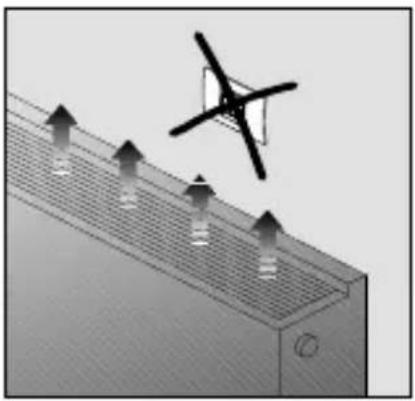
natural_image
Diagram showing a wind turbine above a roof with upward arrows indicating airflow or movement (no text or symbols present)
natural_image
Interior kitchen scene with sink, drain, and microwave fan (no text or symbols)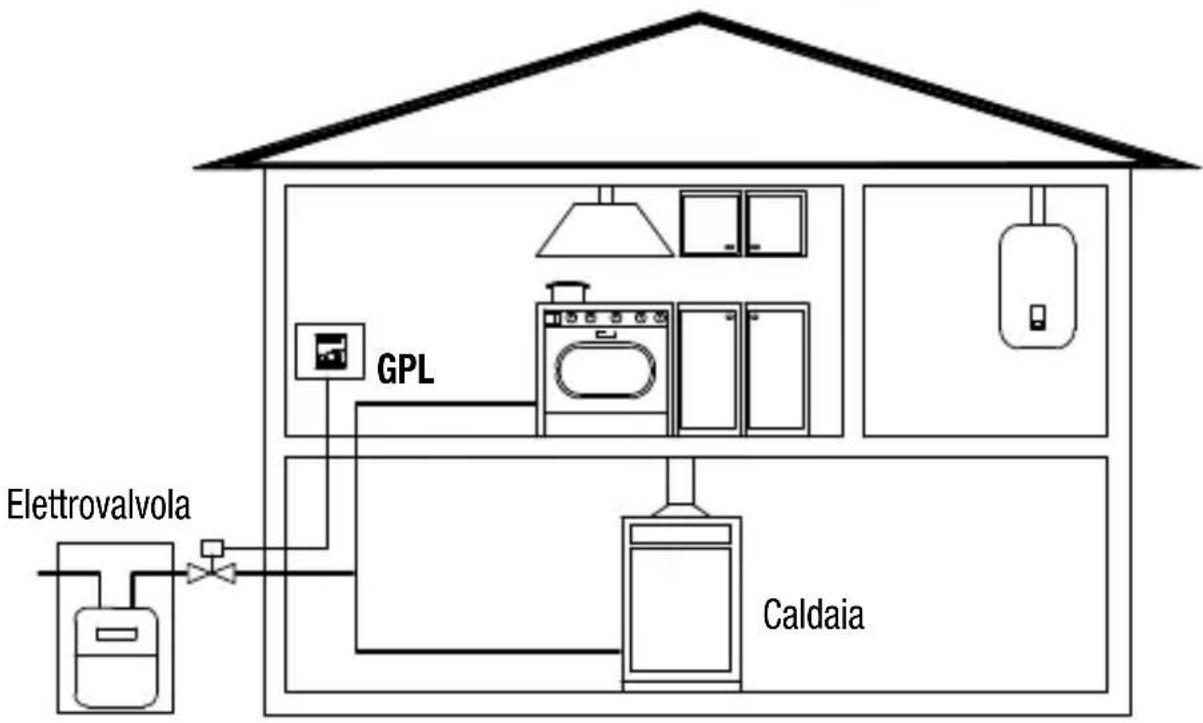
flowchart
graph TD
    A["Elettrovalvola"] --> B["Caldaia"]
    B --> C["GPL"]
    C --> D[" appliances: oven, refrigerator, kitchen, etc."]
    D --> E[" appliances: lamp, door, sink, air purifier"]
L'INSTALLAZIONE DEL RIVELATORE DI GAS NON ESONERA DALL'OSSERVANZA DI TUTTE LE REGOLE RIGUARDANTI LE CARATTERISTICHE, L'INSTALLAZIONE E L'USO DEGLI APPARECCHI A GAS, LA VENTILAZIONE DEI LOCALI E LO SCARICO DEI PRODOTTI DELLA COMBUSTIONE PRESCRITTI DALLE NORME UNI ATTUATIVE DELL'ART. 3 DELLA LEGGE 1083/71 E DALLE DISPOSIZIONI DI LEGGE VIGENTI NEL PAESE INTERESSATO.
L (+)
N (-)
12V ac/dc

flowchart
graph TD
    A["1"] --> B["2"]
    B --> C["3"]
    C --> D["4"]
1 NA/NC, 10A (NA) / 3A (NC) - 250V ac
natural_image
Exploded view diagram of an electronic device showing internal components and casing (no text or labels)natural_image
Line drawing of a rectangular electronic device with a display screen and internal components (no text or symbols)Descrizione comandi

- Thank you for selecting this Gewiss product.
Gewiss products have been designed with attention to detail and built using only the very best materials. Gewiss products will guarantee excellent and lasting performance. - The installer is kindly requested to fill out this leaflet and then hand it to the end user, asking that he/she carefully read it.
- Carefully read the instructions below as they provide important information on how the gas detector works, how it should be fitted and serviced (routine and extraordinary maintenance) and what to do with it once it reaches the end of its expected life.
- The manufacturer may not be held liable for injury to persons or pets or damage caused by the use of the gas detector in situations and conditions other than those indicated in the instructions below.
- The manufacturer may not be held liable in the case that the detector is sold in non-original packaging. Immediately after removing the product from its packaging, make sure that it is not damaged.
- Make sure that the main power supply has been switched off before attempting to fit the device or touch the wiring.
- The gas detector will only work when plugged in to the mains. A device has a one minute delay after a blackout or during installation, during which time its electronic components are reset (see how it works - page 26).
- The sensor reaches full efficiency after 10 days from plugging in.
- Check that the detector is suitable for the type of gas it is expected to detect.
- Before connecting the detector, make sure that the data on its ratings plate match the mains supply.
- Connect the detector as indicated in the drawings on page 23.
- All System-Playbus products must be fitted in compliance with HD 384 - IEC 364 standards for domestic appliances and similar devices, in dust-free areas and where there is no need for special water-proofing protection.
- Always contact an authorised technician or Gewiss's own customer service ("SAT" - see page 82) if the detector is faulty and/or malfunctions and in the case of extraordinary maintenance and scrapping.
INDEX
GENERAL DESCRIPTION
- Functions 18
INSTALLATION INSTRUCTIONS
- Technical features 19
- Application logic 20
- Terminals 22
- Wiring diagrams 23
- Assembly 24
OPERATING INSTRUCTIONS
- Description of the controls 25
- How it works 26
- Test procedure 28
- Recommendations for proper use 28
Functions
System-Playbus electronic gas detectors for domestic use:
• detect the presence of combustible gas
- activate a solenoid valve via an internal circuit that cuts off the supply of gas at its source and must be manually reset
- signal an alarm giving an acoustic and luminous warning.
INSTALLATION INSTRUCTIONS
Technical features
Gas detector with tin dioxide semiconductor sensor*.
Acoustic/luminous alarm signal.
Output relay with hermetically sealed contacts that control the gas cut-off solenoid valve.
TECHNICAL FEATURES
• Power source 12V ac/dc +10/-15%
• Electrical input 2VA
• Alarm threshold 9% LIE (lower limit of esplosivity)
• Acoustic alarm piezoelectric siren producing 85dB at 1 m
- Relay output one switching contact
1 NO/NC, 10A (NO) / 3A (NC) - 250V ac
- Working temperature from +5ircC to +40ircC
- Relative humidity +30 - 90%, condensation free
- Fixing slots into System-Playbus bracket
- Size 2 System-Playbus modules
- Once installed and plugged in, the detector will last for 5 years.
RELEVANT STANDARDS
• EN 50081-1; EN 50082-1; CEI 216-8
* The sensor reaches full efficiency after 10 days from plugging in.
INSTALLATION INSTRUCTIONS
Location advice
ADVICE ON POSITIONING
Install the LPG detectors at a maximum of 30cm from the floor and 1-4m from the gas devices.

Location advice
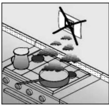
Warning! Do not install the detector near cooking appliances, sinks, air vents, heating and air conditioning equipment, windows, ventilation equipment, and anywhere room conditions could jeopardize the correct operation of the detector.
natural_image
Illustration of a cooking scene with a pot, stove, and air vent (no text or symbols)
natural_image
Diagram of a wind turbine blade with propellers and a propeller above a rectangular base (no text or symbols)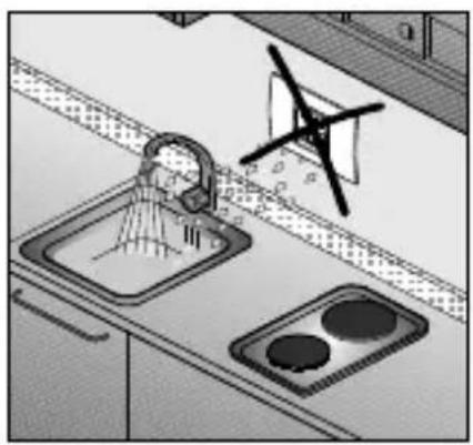
natural_image
Interior kitchen scene showing a sink, wash bottle, and microwave fan (no text or symbols)
flowchart
graph TD
    A["Boiler"] --> B["LPG"]
    B --> C["Solenoid valve"]
    C --> D["Household with roof"]
    style A fill:#f9f,stroke:#333
    style B fill:#ccf,stroke:#333
    style C fill:#cfc,stroke:#333
    style D fill:#fcc,stroke:#333
INSTALLING A GAS DETECTOR DOES NOT IN ANY WAY EXEMPT YOU FROM FOLLOWING ALL THE REGULATIONS REGARDING THE CHARACTERISTICS, INSTALLATION AND USE OF GAS APPLIANCES, ROOM VENTILATION, AND VENTING OF COMBUSTION PRODUCTS AS PROVIDED FOR BY THE UNI STANDARDS IN ACCORDANCE WITH THE LAW 1083/71 ART. 3 AND OTHER PROVISIONS OF THE LAW IN FORCE IN THE COUNTRY INVOLVED.
Terminals
The detector can be connected to 230V - 50 Hz mains supply(if requested) by means of a 230V ac - 12V dc power supply module (GW 20 866 - GW 21 866 - GW 30 518)

L (+)
N (-)
12V ac/dc

flowchart
graph TD
    A["1"] --> B["2"]
    B --> C["3"]
    C --> D["4"]
1 NO/NC, 10A (NO) / 3A (NC) - 250V ac
Contact without potential that cuts off the flow of gas via a solenoid valve with manual resetting (NO or NC).
Additional NO contact for local and/or remote signalling function.
Installation and wiring of electrical equipment and devices must be performed by qualified personnel in compliance with the regulations and laws in force. The manufacturer will not assume any responsibility for the use of products that should be installed according to special room/installation standards; the responsibility for this lies with the installer. The examples shown in this document are for illustration purpose only. When doing the wiring, strictly follow the laws and regulations in force.
Warning: Before installing the product, turn off the power.
Wiring diagrams

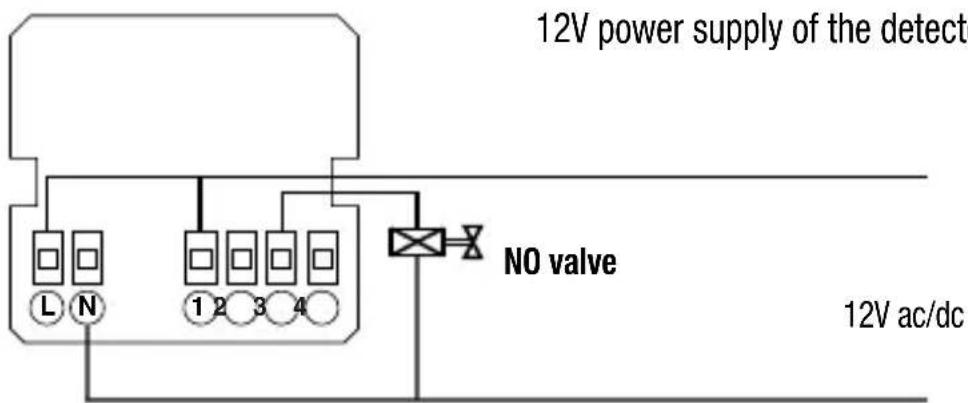

Do not couple GW 20 866, GW 21 866 and GW 30 518 power supply unit to the detector inside the same box.
INSTALLATION INSTRUCTIONS
Assembly
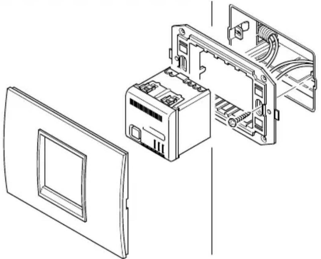
natural_image
Exploded view diagram of an electronic device showing internal components and casing (no text or labels)After installing the detector, the installer should attach the printed sticker on the detector in the pack as shown in the figure below. This sticker indicates the recommended date for replacement of the detector.
Once installed and plugged in, the detector will last for 5 years.
| 2007 |
| 2008 |
| 2009 |
| 2010 |
| 2011 |
| 2012 |
| 2013 |
| 2014 |
| 2015 |
| 2016 |
| 2017 |

natural_image
Line drawing of a wall-mounted electronic device with a display screen and ports (no text or symbols)OPERATING INSTRUCTIONS
Description of the controls


How it works

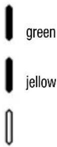
The first time the detector is switched on, it performs an initialization phase lasting 60 seconds during which the detector is not operational.


Once the initialization phase has ended, the detector is ready for normal operation.
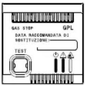

If there is a fault in the detector sensor, the green LED and the yellow LED are steady on.
How it works

Device alarm activated.
When the alarm threshold is exceeded the green and red LEDs instantly light up and the acoustic signal is activated. After 20 seconds the relay switches over (solenoid valve command).

When the alarm situation ends, the detector automatically returns to its normal operating mode.

WARNING: In the event of an alarm:
1) Put out any live flames.
2) Close the valve on the liquid gas bottle containing LPG.
3) Do not switch lights on or off. Do not use electrical appliances or devices.
4) Open doors and windows to increase the air circulation.
If the alarm stops, find out what set off the alarm and act accordingly.
If the alarm continues and you cannot find what set off the alarm or cannot eliminate it, leave the building immediately and call the emergency services from an external line.
WARNING: a smell of gas might be detected before the appliance gives the alarm.
OPERATING INSTRUCTIONS
Test procedure
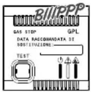
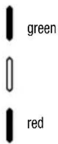
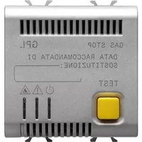
By pressing the Test key, the buzzer is activated (red and green LEDs steady on)


By keeping the Test key down for more than 20 seconds, the relay also switches over (buzzer activated, red and green LEDS steady on).
Recommendations for proper use
- Do not put cloths containing Alcohol, Acetone, Ammonia, Bleach, or Solvents near the gas detector.
- Do not spray anything near the gas detector.
- Do not put lighters or cylinders with the gas turned on near the gas detector.
- Steam from cooking or polluting dust can alter sensor performance over time.
- Do not open or tamper with the appliance: danger of electric shocks and malfunctions.
- Only use a slightly damp cloth to clean the appliance.
GEWISS
FRANÇAIS
natural_image
Illustration of a kitchen scene with a pot, stove, and flying airlock (no text or symbols)
natural_image
Diagram of a wind turbine blade with four blades and an aircraft flying overhead (no text or symbols)
natural_image
Interior kitchen scene showing a sink, wash bottle, and microwave fan (no text or symbols)
flowchart
graph TD
    A["Electrovanne"] --> B["Gaz Auto"]
    B --> C["Chaudière"]
    C --> D["Electrovanne"]
    style A fill:#f9f,stroke:#333
    style B fill:#ccf,stroke:#333
    style C fill:#cfc,stroke:#333
    style D fill:#fcc,stroke:#333
L'INSTALLATION DU DETECTEUR DE BUTANE/PROPANE NE DISPENSE EN AUCUN CAS DU RESPECT DE TOUTES LES REGLES CONCERNANT LES CARACTERISTIQUES, L'INSTALLATION ET L'UTILISATION DES APPAREILS A BUTANE/PROPANE, LA VENTILATION DES LOCAUX ET LE TRAITEMENT DES PRODUITS DE LA COMBUSTION PRESCRITES PAR LES NORMES UNI METTANT A EXECUTION L'ART. 3 DE LA LOI 1083/71 ET PAR LES DISPOSITIONS LÉGALES EN VIGUEUR DANS LE PAYS EN QUESTION.
Description des bornes
L (+)
N (-)
12V ac/dc

1 NA/NC, 10A (NA) / 3A (NC) - 250V ac
natural_image
Exploded view diagram of an electronic device showing internal components and casing (no text or labels)natural_image
Line drawing of a wall-mounted electronic device with a display screen and control buttons (no text or symbols)INSTRUCTIONS POUR L'EMPLOI
natural_image
Illustration of a cooking scene with a pot, stove, and flying airlock (no text or symbols)
natural_image
Diagram showing a wind turbine blade with four blades and an aircraft flying overhead (no text or symbols)
natural_image
Interior kitchen scene with sink, washer, and microwave fan (no text or symbols)
flowchart
graph TD
    A["Electroválvula"] --> B["Caldera"]
    B --> C["GPU"]
    C --> D["Control Panel"]
    D --> E["Chamber"]
    E --> F["Control Panel"]
    F --> G["Control Panel"]
    G --> H["Control Panel"]
    H --> I["Control Panel"]
    I --> J["Control Panel"]
    J --> K["Control Panel"]
    K --> L["Control Panel"]
    L --> M["Control Panel"]
    M --> N["Control Panel"]
    N --> O["Control Panel"]
    O --> P["Control Panel"]
    P --> Q["Control Panel"]
    Q --> R["Control Panel"]
    R --> S["Control Panel"]
    S --> T["Control Panel"]
    T --> U["Control Panel"]
    U --> V["Control Panel"]
    V --> W["Control Panel"]
    W --> X["Control Panel"]
    X --> Y["Control Panel"]
    Y --> Z["Control Panel"]
L (+)
N (-)
12V ac/dc

flowchart
graph TD
    A["1"] --> B["2"]
    B --> C["3"]
    C --> D["4"]
1 NA/NC, 10A (NA) / 3A (NC) - 250V ac
natural_image
Exploded view diagram of an electronic device showing internal components and casing (no text or labels)natural_image
Line drawing of a wall-mounted electronic device with a display screen and ports (no text or symbols)natural_image
Illustration of a kitchen scene with a pot, stove, and air duct (no text or symbols)
natural_image
Diagram of a wind turbine blade with propellers and a propeller above it, showing no text or symbols.
natural_image
Illustration of a kitchen sink with a hand washing it, two pots on the side, and a wall-mounted air vent (no text or symbols)
flowchart
graph TD
    A["Heizkessel"] --> B["Flüssiggas"]
    B --> C["Household with Lighting Panel"]
    B --> D["Electricity Tank"]
    B --> E["Refrigerator"]
    B --> F["Main Dish"]
    B --> G["Induction System"]
    B --> H["Control Panel"]
    B --> I["Refrigerator"]
    B --> J["Electroventil"]
L (+)
N (-)
12V ac/dc

flowchart
graph TD
    A["1"] --> B["2"]
    B --> C["3"]
    C --> D["4"]
1 NA/NC, 10A (NA) / 3A (NC) - 250V ac
natural_image
Exploded view diagram of an electronic device showing internal components and casing (no text or labels)natural_image
Line drawing of a wall-mounted electronic device with a display screen and control buttons (no text or symbols)Where affixed on the equipment or package, the barred waste bin sign indicates that the product must be separated from other waste at the end of its working life for disposal. At the end of use, the user must deliver the product to a suitable recycling centre or return it to the dealer when purchasing a new product. Adequate disposal of the decommissioned equipment for recycling, treatment and environmentally compatible disposal contributes in preventing potentially negative effects on the environment and health and promotes the reuse and/or recycling of equipment materials. Gewiss actively participates in activities that promote the correct reuse, recycling and recovery of electric and electronic equipment. Abusive product disposal by the user is punishable by law with administrative sanctions. For further information, please contact your local sanitation service or product dealer.

According to article 9 paragraph 2 of the European Directive 2004/108/EC and to article R2 paragraph 6 of the Decision 768/2008/EC, the responsible for placing the apparatus on the Community market is:
GEWISS S.p.A Via A. Volta, 1 - 24069 Cenate Sotto (BG) Italy Tel: +39 035 946 111 Fax: +39 035 945 270 E-mail: qualitymarks@gewiss.com


+39 035 946 111
8.30 - 12.30 / 14.00 - 18.00

- NA/NC, 10A (NA) / 3A (NC) - 250V ac
- Descrizione comandi
- INDEX
- GENERAL DESCRIPTION
- INSTALLATION INSTRUCTIONS
- OPERATING INSTRUCTIONS
- Functions
- Technical features
- RELEVANT STANDARDS
- Location advice
- ADVICE ON POSITIONING
- Terminals
- NO/NC, 10A (NO) / 3A (NC) - 250V ac
- Wiring diagrams
- How it works
- Device alarm activated.
- WARNING: In the event of an alarm:
- Test procedure
- Recommendations for proper use
- GEWISS
- FRANÇAIS
- Description des bornes
- INSTRUCTIONS POUR L'EMPLOI
Brand : Gewiss
Model : GW20868
Category : Gas detector