WCR6060FS - Cooker Wolf Power - Free user manual and instructions
Find the device manual for free WCR6060FS Wolf Power in PDF.

Frequently Asked Questions - WCR6060FS Wolf Power
User questions about WCR6060FS Wolf Power
0 question about this device. Answer the ones you know or ask your own.
Ask a new question about this device
Download the instructions for your Cooker in PDF format for free! Find your manual WCR6060FS - Wolf Power and take your electronic device back in hand. On this page are published all the documents necessary for the use of your device. WCR6060FS by Wolf Power.
USER MANUAL WCR6060FS Wolf Power
Our objective is to make this product provide you with the best output which is manufactured in our modern facilities in a careful working environment, in compliance with total quality concept.
Therefore, we suggest you to read the user manual carefully before using the product and, keep it permanently at your disposal.
NOT:
This user manual is prepared for more than one model. Some of the features specified in the Manual may not be available in your appliance.
THIS APPLIANCE SHALL BE INSTALLED IN ACCORDANCE WITH THE REGULATIONS IN FORCE AND ONLY USED IN A WELL VENTILATED SPACE. READ THE INSTRUCTIONS BEFORE INSTALLING OR USING THIS APPLIANCE
CONTENTS
Installation of your oven
Technical features of your oven
Important warnings
If the appliance does not operate
Description of oven & control panel
Using cooker section
Using oven section
Using the heat shield
Maintenance and cleaning
INSTALLATION OF YOUR OVEN
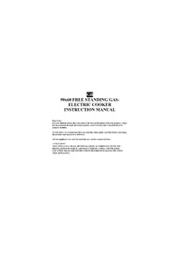
Electrical Connection and Security:
- Your oven requires 6 or 32 Ampere fuse according to the appliance's power. If necessary, installation by a qualified electrician is recommended.
- Your oven is adjusted in compliance with 220-240 V AC, 50-60 Hz (or 230 V / 400 V AC, 50 - 60 Hz.) electric supply. If the mains are different from this specified value, contact your authorized service.
- Electrical connection of the oven should only be made by the sockets with earth system installed in compliance with the regulations. If there is no proper socket with earth system in the place where the oven will be placed, immediately contact a qualified electrician. Manufacturer shall never be responsible from the damages that will arise because of the sockets connected to the appliance with no earth system. If the ends of the electrical connection cable are open, according to the appliance type, make a proper switch installed in the mains by which all ends can be disconnected in case of connecting / disconnecting from / to the mains.
- If your electric supply cable gets defective, it should definitely be replaced by the authorized service or qualified electricians in order to avoid from the dangers.
- Electrical cable should not touch the hot parts of the appliance.
- Please operate your oven in dry atmosphere.
Gas Connection and Security:
- Fit the clamp to the hose. Push one of the hose until it goes to the end of the pipe.
- For the sealing control; ensure that the buttons in the control panel are closed, but the gas cylinder is open. Apply some soap bubbles to the connection. If there is gas leakage, there will be foaming in the soaped area.
- The oven should be using a well ventilation place and should be install on flat ground.
- Re-inspect the gas connection.
- When placing your oven to its location, ensure that it is at the counter level. Bring it to the counter level by adjusting the feet if necessary.
- Do not make gas hose and electrical cable of your oven go through the heated areas, especially through the rear side of the oven. Do not move gas connected oven. Since the forcing shall loosen the hose, gas leakage may occur.
text_image
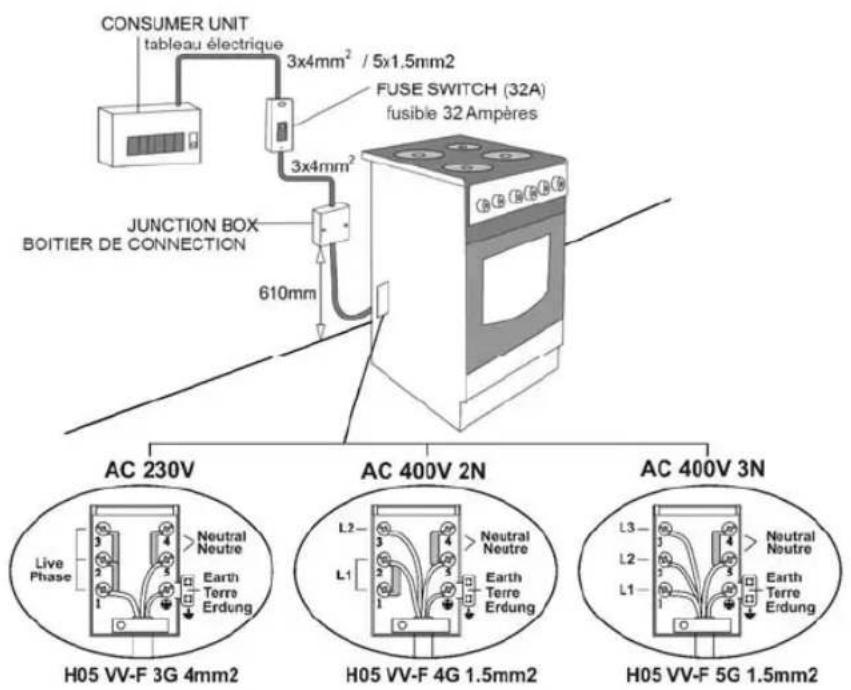
CONSUMER UNIT tableau électrique 3x4mm² / 5x1.5mm2 FUSE SWITCH (32A) fusible 32 Ampères JUNCTION BOX BOITIER DE CONNECTION 610mm AC 230V Neutral Neutre H05 VV-F 3G 4mm2 AC 400V 2N Neutral Neutre L2 L1 H05 VV-F 4G 1.5mm2 AC 400V 3N Neutral Neutre L3 L2 L1 H05 VV-F 5G 1.5mm2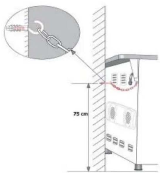
text_image
75 cm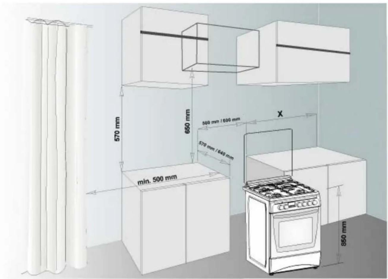
text_image
570 mm 650 mm 580 mm / 1600 mm 570 mm / 640 mm min. 500 mm X 850 mmTECHNICAL FEATURES OF YOUR OVEN
| SPECIFICATIONS 50 x 5 | 5 50 x 60 60 x 58 | 60 x 60 | ||
| Outer width 500 mm 500 mm | 500 mm 600 mm | |||
| Outer depth 565 mm 635 mm | 580 mm 635 mm | |||
| Outer height 855 mm 855 mm | 855 mm 855 mm | |||
| Inner width 365 mm 365 mm | 465 mm 465 mm | |||
| Inner depth 410 mm 410 mm | 410 mm 410 mm | |||
| Inner height 355 mm 355 mm | 355 mm 355 mm | |||
| Lamp power * 15 W | ||||
| Thermostat 50 - 280 °C | ||||
| Bottom heating element 1000 W | 1000 W 1200 W | 1200 W | ||
| Top heating element 800 W 800 W | 1000 W 1000 W | |||
| Turbo heating element * | ---- | 1800 W 2200 W | 2200 W | |
| Grill heating element * | 1500 W 1500 W | 2000 W 2000 W | ||
| Supply voltage | 220-240 V AC, 50-60 Hz (or 230V/400V AC, 50 - 60 Hz.) | |||
| Hot plate 145 mm* | 1000 W | |||
| Hot plate 180 mm* | 1500 W | |||
| Hotplate rapid 145 mm * | 1500 W | |||
| Hotplate rapid 180 mm * | 2000 W | |||
*: Optional
| BURNER INJECTOR VALUES ACCORDING TO THE GAS TYPE | LPG Natural gas Natural gas | |||||
| G 30-30 G 20-20 G 25-25 | ||||||
| Wok Burner | Injector | mm | 0.96 | 1.30 | 1.40 | |
| Power | KW | 3.60 | 3.35 | 3.66 | ||
| Rapid Burner | Injector | mm | 0.85 | 1.15 | 1.20 | |
| Power | KW | 3.00 | 2.77 | 3.00 | ||
| Semi-rapid Burner | Injector | mm | 0.65 | 0.97 | 0.95 | |
| Power | KW | 1.78 | 1.78 | 1.61 | ||
| Auxiliary Burner | Injector | mm | 0.50 | 0.72 | 0.70 | |
| Power | KW | 0.88 | 0.99 | 0.88 | ||
| Oven Burner | Injector | mm | 0.70 | 0.97 | 0.95 | |
| Power | KW 2.16 / 2.22 1.83 / 2.00 | 1.72 / 1.70 | ||||
| Grill Burner | Injector | mm 0.60 / 0.65 0.95 | 0.92 / 0.95 | |||
| Power | KW 2.22 / 1.72 1.78 / 1.85 | 1.50 / 1.60 | ||||
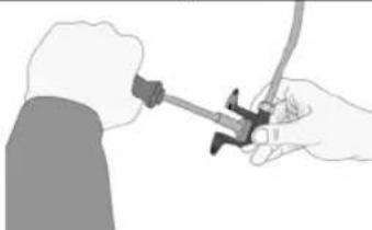
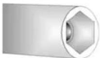
Nozzle change operation:
- Please use driver with special head for removed and install nozzle as figure-1
- Please remove nozzle (figure-2) from burner with special nozzle driver and install new nozzle (figure-3)
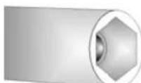
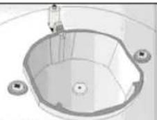
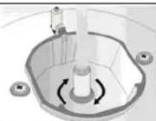
Figure - 1 Figure - 2 Figure - 3
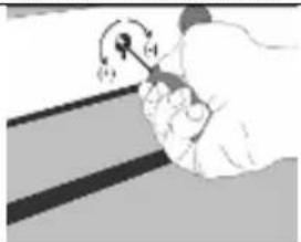
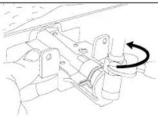
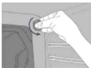
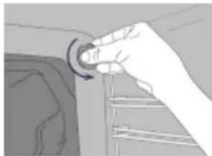
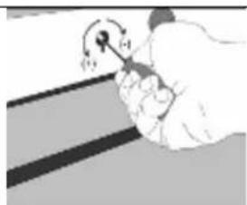
Reduced Flame Gas Cock Adjustment:
In order to adjust your oven to the gas type, make the adjustment for reduced flame carefully by turning with a small screwdriver as shown below on the screw in the middle of the gas cocks as well as nozzle changes.
| From LPG to Natural gas From Natural gas to LPG | ||
| Rapid Burner | 3 turns anticlockwise | 3 turns clockwise |
| Semi-rapid Burner | 2.5 turns anticlockwise | 2.5 turns clockwise |
| Auxiliary Burner | 2 turns anticlockwise | 2 turns clockwise |
| Wok Burner | 4 turns anticlockwise | 4 turns clockwise |
| Oven Burner | 4,5 turns anticlockwise | 4,5 turns clockwise |
| Grill Burner | 4 turns anticlockwise | 4 turns clockwise |
 |  | |
| Figure - 4 | Figure - 5 | |
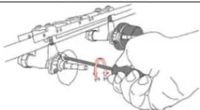
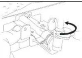
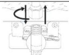
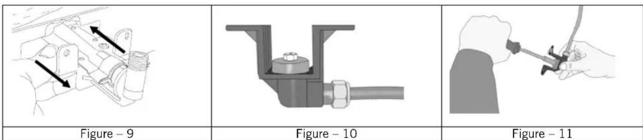
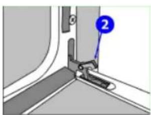
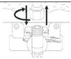
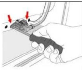
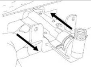
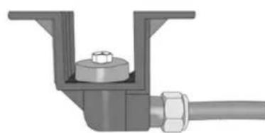
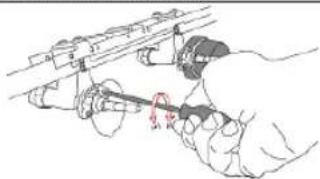
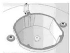
For oven burners:
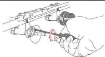
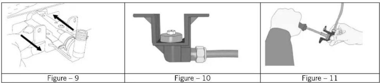
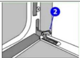
- Please remove nut from on nozzle body with nut driver and disconnect gas pipe from body as Picture-6 and Picture-7.
- Please remove nozzle body and burner from cavity as Picture-8 and remove nozzle from injector body (picture-9) and change. Than re-install nozzle body and burner on cavity by screws.
 |  |  |
| Figure - 6 | Figure - 7 | Figure - 8 |
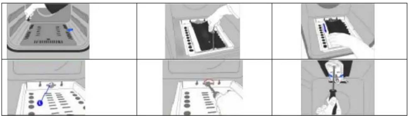
If your oven has another type of oven burner, oven burner nozzle replacement will be:
natural_image
Three-panel illustration showing a device being processed into a rack, with no visible text or symbols.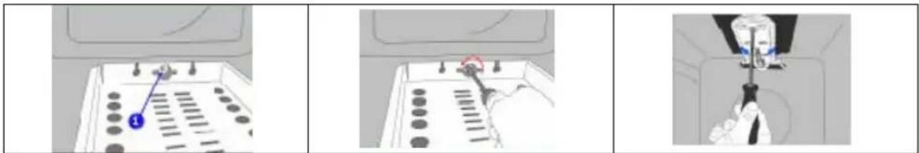
natural_image
Three-panel illustration showing a hand operating a screwdriver on a device, with no visible text or symbols.IMPORTANT WARNINGS
-
Pay attention to minimum health and safety requirements.
-
The cooker is supplied setup according to the conditions shown on the rating label which is stuck to the rear of the appliance. From this sticker you can learn for which gas type (LPG or NG) this appliance is configured when supplied.
-
Keep the electrical cable of your oven away from the hot areas.
-
If the supply cord is damaged, it must be replaced by the manufacturer its services agent or similar qualified persons in order to avoid hazard.
-
Ensure that the appliance is switches off before replacing the lamp to avoid the possibility of electric shock.
-
In case of power failure, readjust your timer definitely. Otherwise, the oven will not operate (Digital Timer).
-
Your oven can be having different output pressure according to your countries gas and pressure specifications. Be sure that the cooker is configured correctly for local requirements (for example, the jets must be suitable for local gas type and gas pressure).
-
Connect your oven to LPG in shortest way and without any leakage. Min. 40 cm Max. 125 cm.
-
When making gas leakage check, never use any flame type like those of lighter, matches, cigarette fire or similar ones.
-
Usage of your appliance creates moisture and heath in the room it is placed, make sure that your kitchen is ventilated well. Maintain the natural ventilation ducts properly.
-
CAUTION! Do not touch hot parts with bare hands and keep children well supervised
-
When the oven is hot never touch the oven glass by hand.
-
Before starting to use your appliance, keep curtain, tulle, paper or inflammable things away from your appliance. Do not keep combustible or inflammable things in or on the appliance.
-
Your oven is produced for cooking purpose. Please do not use for any other purpose.
-
For disconnection from the supply mains having a contact separation in all poles that provide full disconnection, must be incorporated in fixed wiring in accordance with the wiring rules.
-
Some models are supplied without a plug-an-lead set. In this case please use a flexible cable to suitable for connection to mono phase: H05 VV-F 3 G 4 mm2 or for 3 phase: H05 VV-F 5 G 1.5 mm2
-
This appliance is produced in accordance with the safety regulations. Incorrect use will harm people and appliance.
-
Children should be supervised to ensure that they do not play with the appliance. Never let them play with the appliance.
-
This appliance is not intended for use by persons (including children) with reduced physical, sensory and mental capabilities or lack of experience and knowledge, unless they have been given supervision or instruction concerning the use of the appliance by a person responsible for their safety.
-
Caution: Accessible parts may be hot when the grill is in use. Young children should be kept away"
IF THE APPLIANCE DOES NOT OPERATE
- Please check the plug of power supply cord has a well connection with wall socket or not.
- Please check the electric network.
- Please check the fuse.
- Please check power supply cord for any damage problems.
- If you can not solve the problem, get in contact with manufacturer-supplier service agent or similar qualified persons.
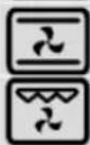
DESCRIPTION OF OVEN and CONTROL PANELS
 | Turnspit |  | Fan |
 | Top+bottom heating element |  | Turbo heating element+fan |
 | Lamp |  | Bottom/Top heating elements+fan |
 | Bottom heating element+fan |  | Grill heating element+fan |
 | Grill heating element+turnspit |  | Grill burner / grill heating element |
 | Grill heating element+lamp |  | Top heating element |
 | Electrical timer |  | Oven burner / Bottom heating element |
 | Flame |  | Ignition lighter |
THERMOSTAT KNOB; In order to operate the oven, thermostat must be adjusted to desired temperature. Your thermostat has a feature of adjustment to 50 - 280 degree.
MECHANIC TIMER KNOB (Optional); In order to operate the oven, timer switch should be adjusted to desired time from 0-90 minute. You can use cooking time table.
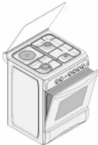
DESCRIPTION OF THE OVEN and CONTROL PANELS
text_image
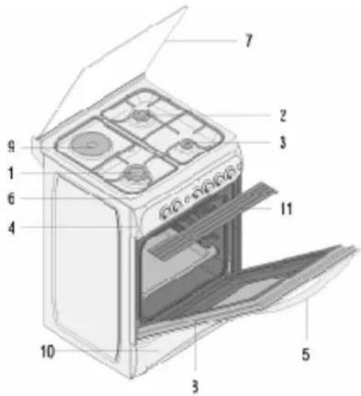
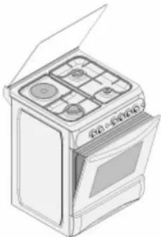
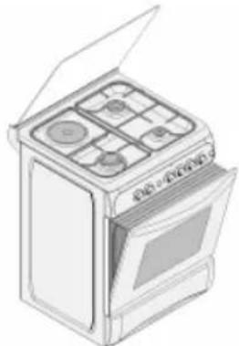
Labeled diagram of an oven with numbered parts for identification| 1. | Rapid burner |
| 2. | Semi-rapid burner |
| 3. | Auxiliary burner |
| 4. | Command panel |
| 5. | Oven handle |
| 6. Top plate | |
| 7. Top lid (Glass or Metal) | |
| 8. | Oven door |
| 9. Hot plate (optional) | |
| 10. Dish warmer drawer | |
| 11. Grill deflector sheet | |
USING COOKER SECTION
Using Gas Burners:
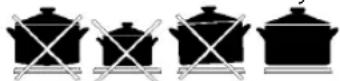
| Wok Burner 24 - 28 cm |
| Big Burner 22 - 26 cm |
| Normal Burner 18 - 22 cm |
| Small Burner 12 - 18 cm Closed Fully |
- In order to obtain maximum output, be careful that the saucepan which will be used should be flat bottomed, and use the saucepans with dimensions given herein above.
- The valves controlling the gas cookers have special security mechanism. In order to light the cooker; Always press on the switch forward and bring it to flame symbol by turning anticlockwise. All of the lighters
shall operate and the cooker you controlled shall light only. Keep the switch pressed until ignition is performed.
Press on the lighter button and turn the knob counter clockwise.
- Do not continuously operate the igniter for more than 15 seconds. If the burner does not ignite, wait minimum one minute before try again. If the burner is extinguished because of any reason, close the gas control valve and wait minimum one minute before try again.
- In models with Gas Security System, when flame of the cooker is extinguished, control valve cuts off the gas automatically. For operate the burners with gas security system you must press the knob and turn counter-clockwise. After the ignition you must wait nearly 5-10 second for gas security systems activation. If the burner is extinguished for of the any reason, close the gas control valve and wait a minimum of one minute before trying again.
Using Hot Plates:
| Hot Plate | LEVEL 1 LEVEL 2 LEVEL 3 LEVEL 4 LEVEL 5 LEVEL 6 | ||||||
| 145 mm | 95 W 155 W 250 W 400 W 750 W 1000 W | ||||||
| 180 mm 115 W 175 W 250 W 600 W 850 W 1500 W | |||||||
| 145 mm Rapid 135 W 165 W 250 W 500 W 750 W 1500 W | |||||||
| 180 mm Rapid 175 W | 220 W 300 W 850 W 1150 W 2000 W | ||||||
- Electric hotplates have standard of 6 temperature levels (as described herein above)
- When using first time, operate your electric hotplate in position 6 for 5 minutes. This will make the agent on your hotplate which is sensitive to heat get hardened by burning.
- Use flat bottomed saucepans which fully contact with the heat as much as you can, so that you can use the energy more productively.
USING OVEN SECTION
Using oven burners:
- If your oven equipped with burners that operates with gas, appropriate knob should be used in order to ignite the burners. Some models have automatic ignition from the knob; it is easy to ignite the burner by turning the knob. Also, burners can be ignited by pressing the ignition button or they can be ignited with a match.
- Do not continuously operate the igniter for more than 15 seconds. If the burner does not ignite, wait minimum one minute before trying again. If the burner is extinguished for of the any reason, close the gas control valve and wait a minimum of one minute before trying again.
Using oven heating elements:
- When your oven is operated first time, an odor will be spread out which will be sourced from using the heating elements. In order to get rid of this, operate it at 250 °C for 45 minutes while it is empty.
- Oven control knob should be positioned to desired value; otherwise oven does not operate.
- Kinds of meals, cooking times and thermostat positions are given in cooking table. The values given in the cooking table are characteristic values and were obtained as a result of the tests performed in our laboratory. You can find different flavors suitable for your taste depending on your cooking and using habits.
- You can make chicken revolving in your oven by means of the accessories.
- Cooking times: The results may change according to the area voltage and material having different quality, amount and temperatures.
- During the time when cooking is being performed in the oven, the lid of the oven should not be opened frequently. Otherwise circulation of the heat may be imbalanced and the results may change.
- Using cake forms while cooking cake gives better result.
- 5 - 10 min. preliminary heating should be done prior cooking.
Cooking Time Table:
| Meals Temperature (°C) Rack position Cooking time (min.) | |||
| Creamed cake 150 - 170 | 2 | 30 - 35 | |
| Pastry | 200 - 220 | 2 | 35 - 45 |
| Biscuit | 160 - 170 | 3 | 20 - 25 |
| Cookie | 160 - 170 | 3 | 20 - 35 |
| Cake | 160 - 180 | 2 | 25 - 35 |
| Braided cookie | 200 - 220 | 2 | 30 - 40 |
| Filo pastry | 180 - 220 | 2 | 35 - 45 |
| Savory pastry | 160 - 180 | 2 | 20 - 30 |
| Lamb meat | 200 - 230 | 1 | 90 - 120 |
| Veal | 200 - 230 | 1 | 90 - 120 |
| Mutton | 210 - 230 | 1 | 90 - 120 |
| Chicken (in pieces) | 210 - 230 | 1 | 75 - 100 |
| Fish | 190 - 210 | 2 | 40 - 50 |
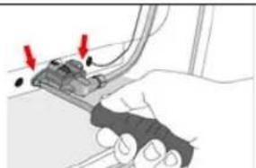
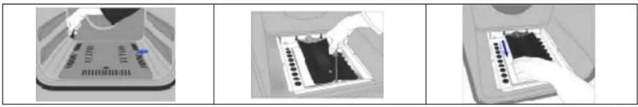
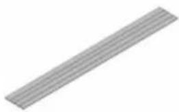
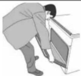
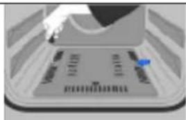
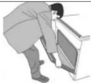
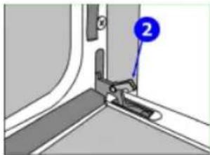
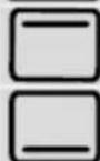
USING GRILL DEFLECTOR PANEL (optional)
- A safety panel is designed to protect control panel and the buttons when the oven is in Grill mode (Figure 1)
- Place the safety panel under control panel by opening the oven front cover glass (Figure 2)
- And then secure the safety panel in between oven and front cover by gently closing the cover. (Figure 3)
- Please use this safety panel in order to avoid the heat to damage control panel and the buttons when the oven is Grill mode.
- It is important for cooking to keep the cover open in specified distance when cooking in grill mode.
- Safety panel will provide an ideal cooking circumstance while protecting control panel and buttons.
natural_image
Simple 3D illustration of a diagonal striped bar (no text or symbols)Figure 1

natural_image
Line drawing of an open kitchen oven with visible door, fan, and door panel (no text or symbols)Figure 2 Figure 3
natural_image
Line drawing of an open oven with multiple panes and a door (no text or symbols)MAINTENANCE and CLEANING
- Disconnect the plug supplying electricity for the oven from the socket.
- While oven is operating or shortly after it starts operating, it is extremely hot. You must avoid touching from heating elements.
- Never clean the interior part, panel, lid, trays and all other parts of the oven by the tools like hard brush, cleaning mesh or knife. Do not use abrasive, scratching agents and detergents.
- After cleaning the interior parts of the oven with a soapy cloth, rinse it and then dry thoroughly with a soft cloth.
- Clean the glass surfaces with special glass cleaning agents.
- Do not clean your oven with steam cleaners.
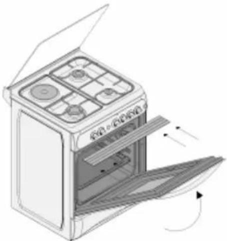
- Before opening the upper lid of the oven, clean spilled liquid off the lid. Also, before closing the lid, ensure that the cooker table is cooled enough.
- Never use inflammable agents like acid, thinner and gasoline when cleaning your oven.
- Do not wash any part of your oven in dishwasher.
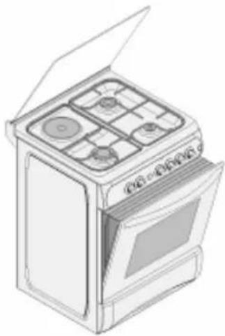
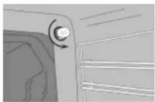
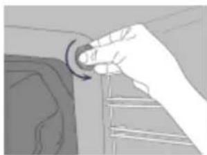
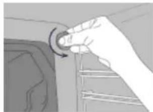
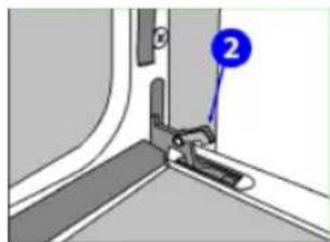
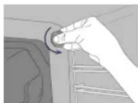
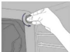
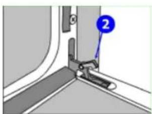
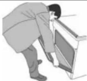
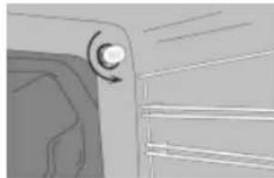
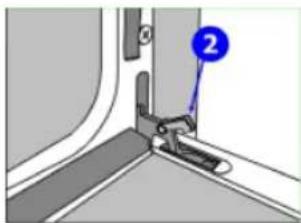
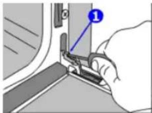
- In order to clean the front glass lid of the oven; remove the fixing screws fixing the handle by means of a screwdriver and remove the oven door. Than clean and rinse it thoroughly. After drying, place the oven glass properly and re-install the handle.
natural_image
Close-up of a mechanical component with a circular motion indicator and textured surface (no text or symbols)□
natural_image
Hand pressing a button on a mechanical component (no text or symbols visible)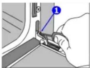
text_image
Diagram showing a hand using a tool to adjust or install a component, with a numbered label pointing to the component.[NO TEXT]
natural_image
Close-up of a mechanical component with a blue numbered marker (2) pointing to a detail, no visible text or symbols.□
natural_image
Illustration of a person bending over a chair (no text or symbols visible)
NOTICE D'UTILISATION DU FOUR GAZ – ELECTRICITE
Cher utilisateur,
text_image
Figure - 1 Figure - 2 Figure - 3natural_image
Hand holding a mechanical component with a red-handled tool, no visible text or symbolsFigure - 5
 |  |  |
| Figure - 6 | Figure - 7 | Figure - 8 |
 |  |  |
| Figure - 9 | Figure - 10 | Figure - 11 |
natural_image
Illustration of a person opening a train car with visible tracks and seats (no text or symbols)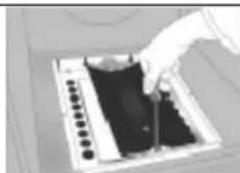
natural_image
Hand operating a mechanical component with a dark base and circular components (no visible text or symbols)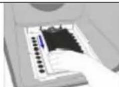
natural_image
Close-up of a computer keyboard with a mouse cursor hovering over it (no visible text or symbols)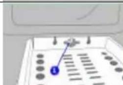
natural_image
Close-up of a mechanical component with circular holes and a blue arrow pointing to a small component (no visible text or symbols)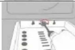
natural_image
Close-up of a hand operating a control panel with buttons and a red pointer (no visible text or symbols)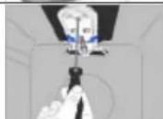
natural_image
Close-up of a gloved hand holding a small object above a mechanical component (no visible text or symbols)MISES EN GARDE IMPORTANTES
text_image
Labeled diagram of a 11-pin oven with numbered parts for identificationDESCRIPTION DU FOUR ET DU PANNEAU DE COMMANDE
natural_image
Simple diagonal gray stripe on white background (no text or symbols)Figure 1

natural_image
Line drawing of an open oven with four panes and a door, showing interior airflow direction (no text or symbols)Figure 2
natural_image
Line drawing of an open oven with multiple panes and a door (no text or symbols)Figure 3
MAINTENANCE et NETTOYAGE
natural_image
Close-up of a mechanical component with a circular arrow indicating rotation (no text or symbols visible)□

natural_image
Hand holding a circular knob with a curved arrow, pointing to a mechanical component (no text or symbols visible)
text_image
Diagram showing a hand holding a tool with a numbered label pointing to the component□

natural_image
Close-up of a mechanical component with a blue numbered label pointing to a specific part (no text or symbols visible)□
natural_image
Illustration of a person bending over a chair (no text or symbols visible)KOMBINOVANÝ SPORÁK PLYN- ELEKTŘINA NÁVOD K POUŽITÍ
Vážený uživateli;
text_image
Figure - 1 Figure - 2 Figure - 3natural_image
Hand holding a tool with a circular arrow icon above it, no visible text or symbolsFigure - 4
natural_image
Illustration of a hand using a tool to adjust or install a mechanical component (no text or symbols visible)Figure - 5
| Figure - 6 | Figure - 7 | Figure - 8 |
natural_image
Six-panel sequence showing a hand operating a device in different states (no visible text or symbols)DŮLEŽITÁ UPOZORNĚNÍ
text_image
Vertical sequence of icons representing weather, lighting, and energy symbolstext_image
Vertical sequence of icons representing various symbols and concepts, including a stylized airplane, circular symbol, crossed-out box, envelope, and star.text_image
Labeled diagram of an oven with numbered parts for identificationnatural_image
Four black-and-white illustrations of cooking pots with crossed handles, arranged in a row (no text or symbols)natural_image
Line drawing of a two-step kitchen appliance assembly showing open door, vent, and oven with a wooden strip on the left (no text or symbols)natural_image
Close-up of a mechanical component with a circular knob and arrow indicating rotation (no text or symbols)[NO TEXT]
natural_image
Hand holding a circular knob with an arrow, pointing to a mechanical component (no text or symbols visible)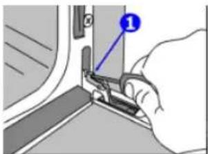
text_image
Diagram showing a hand using a tool to adjust or install a component, with a numbered label pointing to the component.[NO TEXT]
natural_image
Close-up of a mechanical assembly with a blue numbered component (2) pointing to a detail on a curved panel or bracket (no text or symbols visible)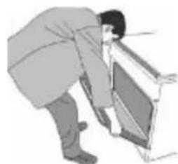
natural_image
Illustration of a person bending over a computer monitor (no text or symbols visible)HU
KOMBINÁLT TÜZHELY HASZNÁLATI ÚTMUTATÓ
Tisztelt Vásárló!
natural_image
Six-panel technical illustration showing a device's internal components and tool path, no text or symbols present.FONTOS FIGYELMEZTETÉSEK ÉS BIZTONSÁGI ELŐÍRÁSOK
text_image
Vertical sequence of icons representing weather, lighting, and energy symbols in Chinesetext_image
Vertical sequence of icons representing various symbols or concepts, including a gear, circular, water drop, envelope, and star.text_image
Labeled diagram of a 11-pin oven with numbered parts for identificationnatural_image
Four black-and-white silhouettes of cooking pots with crossed handles, arranged in a row (no text or symbols)A SÜTÖ HASZNÁLATA
Sütőégő:
natural_image
Simple 3D illustration of a diagonal striped rectangular bar (no text or symbols)- ábra
natural_image
Line drawing of an open oven with four panes and a door, showing internal structure and airflow direction (no text or symbols)- ábra
natural_image
Line drawing of a standard open oven with four panes and a door (no text or symbols)- ábra
natural_image
Close-up of a mechanical component with a circular knob and textured surface (no visible text or symbols)□
natural_image
Hand holding a circular knob with an arrow, pointing to a textured surface (no text or symbols visible)
text_image
Diagram showing a hand using a tool to adjust or install a component, with a numbered label pointing to the component.□

natural_image
Close-up of a mechanical component with a numbered label pointing to a detail (no readable text or symbols)□

natural_image
Illustration of a person bending over a chair (no text or symbols visible)natural_image
Hand holding a pointer with a circular arrow labeled 'N' pointing upward (no text or symbols beyond the label)obr. 4
natural_image
Illustration of a hand using a tool to adjust or install a mechanical component (no text or symbols visible)obr. 5
text_image
Labeled diagram of an oven with numbered parts for identificationnatural_image
Four black-and-white illustrations of cooking pots with crossed handles, arranged in a row (no text or symbols)POUŽÍVANIE RÚRY
Plynovej:
natural_image
Illustration of a kitchen oven with open door and side view, showing internal components and airflow direction (no text or symbols)obr. 6
obr. 6 obr. 6
ÚDRŽBA A ČISTENIE
natural_image
Close-up of a mechanical component with a circular knob and arrow indicating rotation (no text or symbols)□
natural_image
Hand holding a circular knob with a curved arrow, pointing to a surface (no text or symbols visible)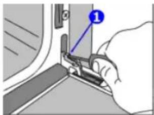
text_image
Diagram showing a hand using a tool to adjust or install a component, with a numbered label pointing to the component.□
text_image
Technical diagram showing a mechanical assembly with labeled component '2'□

natural_image
Illustration of a person bending over a window frame (no text or symbols)Kjære kunde ;
natural_image
3D rendering of a circular basin with two side sinks and a central outlet (no text or symbols)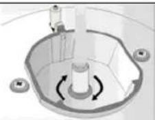
natural_image
3D diagram of a mechanical component with rotating arrows indicating rotational motion (no text or symbols)text_image
Vertical sequence of icons representing weather, solar, wind, and fire symbolsRoterende grillspyd
∅vre varmeelementet+nederste varmeelementet
Stekeovnsbelysning
Varmluft+ nederste varmeelementet
Grillelementet er pa+ Roterende grillspyd
text_image
Vertical sequence of icons representing various symbols or concepts, including a stylized airplane, circular arrow, crossed-out box, envelope, and star.varmluft
turbo varmeelement+varmluft
∅vre varmeelementet+nederste varmeelementet +varmluft

Grillelementet er pa+ varmluft
Grillelementet er pa

∅vre varmeelementet
natural_image
Four black-and-white illustrations of cooking pots with crossed handles, arranged in a row (no text or symbols)natural_image
Line drawing of an open oven with four panes and a door, showing internal structure and airflow direction (no text or symbols)Fig. 2
natural_image
Line drawing of an open oven with multiple panes and a door (no text or symbols)Fig. 3
natural_image
Close-up of a door handle with a circular knob and horizontal lines, no visible text or symbols□
natural_image
Hand pressing a button on a surface, showing motion direction (no text or symbols)
text_image
Diagram showing a hand holding a tool with a numbered label pointing to a component, likely illustrating a procedure or installation step.[ ]
text_image
Technical diagram showing a mechanical component with labeled part '2' and numbered marker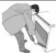
natural_image
Illustration of a person bending over a wall-mounted device (no text or symbols visible)FIN
Arvoisa asiakas;
text_image
Vertical sequence of icons representing weather, lighting, and energy symbols in Chinesetext_image
Vertical sequence of icons representing various symbols or concepts, including a bird, refresh, water drop, and star.tuuletin
text_image
Labeled diagram of a portable stove interior with numbered components for identificationnatural_image
Illustration of a door handle with a circular knob and horizontal lines, no text or symbols present□
natural_image
Hand holding a circular knob with a curved arrow, pointing to a mechanical component (no text or symbols visible)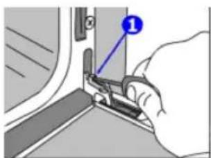
text_image
Diagram showing a hand using a tool to adjust or install a component, with a numbered label pointing to the component.[ ]
natural_image
Close-up of a mechanical component with a numbered label pointing to a detail (no readable text or symbols)□
natural_image
Illustration of a person bending over a chair (no text or symbols visible)natural_image
Hand holding a circular knob with a curved arrow, pointing to a textured surface (no text or symbols visible)[ ]
natural_image
Close-up of a door handle with a circular knob and arrow indicator (no text or symbols)
natural_image
Illustration of a person bending over a chair (no text or symbols visible)□
text_image
Technical diagram showing a mechanical assembly with labeled component '2'□
text_image
Diagram showing a hand holding a tool with a numbered label pointing to a component, likely illustrating a procedure or installation step.natural_image
Line drawing of an open oven with visible door, fan, and door panel (no text or symbols)
natural_image
Line drawing of an open oven with four panes and a door, showing internal compartments (no text or symbols)1- صورة
2- صورة
3- صورة
text_image
Labeled diagram of an oven with numbered parts for identificationnatural_image
Four black-and-white illustrations of cooking pots with crossed handles, arranged horizontally (no text or symbols)natural_image
Illustration of hands using a tool to adjust or install a mechanical component (no text or symbols visible)5- صورة
natural_image
Hand holding a tool with a circular arrow indicating rotation (no text or symbols)4 صورة
natural_image
Diagram of a mechanical or fluidic component with rotating arrows, no visible text or symbols3- صورة
natural_image
Top-down view of a circular basin with two side pools and a central outlet (no text or symbols visible)2- صورة
1- صورة
عملية تغير الحلمة: