WE 24180 MVT - Grinder METABO - Free user manual and instructions
Find the device manual for free WE 24180 MVT METABO in PDF.

Frequently Asked Questions - WE 24180 MVT METABO
User questions about WE 24180 MVT METABO
0 question about this device. Answer the ones you know or ask your own.
Ask a new question about this device
Download the instructions for your Grinder in PDF format for free! Find your manual WE 24180 MVT - METABO and take your electronic device back in hand. On this page are published all the documents necessary for the use of your device. WE 24180 MVT by METABO.
USER MANUAL WE 24180 MVT METABO
WEPBA 24-180 MVT Quick
WEPBA 24-230 MVT Quick
W 26-180 MVT
W 26-230 MVT
WE 26-230 MVT Quick
WEA 26-230 MVT Quick
WEPBA 26-230 MVT Quick

W 22-180 MVT, W 22-230 MVT, W 24-180 MVT, W 24-230 MVT, W 26-180 MVT, W 26-230 MVT:
Original instructions
1. Declaration of Conformity
We, being solely responsible: Hereby declare that these angle grinders, identified by type and serial number 1 , meet all relevant requirements of directives 2 and standards 3 . Technical documents for 4 - see Page 3.
For UK only:
UK We as manufacturer and authorized person to compile the technical file, see *4) on page 3, hereby declare under sole responsibility that these angle grinders, identified by type and serial number *1) on page 3, fulfill all relevant provisions of following UK Regulations S.I. 2016/1091, S.I. 2008/ 1597,S.I.2012/3032 and Designated Standards EN 60745-1:2009+A11:2010,EN 60745-2- 3:2011+A2:2013+A11:2014+A12:2014+A13:2015, EN IEC 63000:2018.
2. Specified Use
Machines fitted with original Metabo accessories are suitable for grinding, sanding, abrasive cutting-off operations and wire brushing metal, concrete, stone and similar materials without the use of water.
The user bears sole responsibility for any damage caused by inappropriate use.
Generally accepted accident prevention regulations and the enclosed safety information must be observed.
3. General Safety Instructions

For your own protection and for the protection of your power tool, pay attention to all parts of the text that are marked with this symbol!

WARNING - Read the operating instructions to reduce the risk of injury.

WARNING - Read all safety warnings, instructions, illustrations and
specifications provided with this power tool.
Failure to follow all instructions listed below may result in electric shock, fire and/or serious injury.
Save all warnings and instructions for future reference.
Always include these documents when passing on your power tool.
4. Special Safety Instructions
4.1 SafetyWarnings Common for Grinding, Sanding, Wire Brushing or Cutting-Off Operations:
a) This power tool is intended to function as a grinder, sander, wire brush, hole cutter or cutoff tool. Read all safety warnings, instructions, illustrations and specifications provided with this power tool. Failure to follow all instructions
listed below may result in electric shock, fire and/or serious injury.
b) Operations such as polishing are not to be performed with this power tool. Operations for which the power tool was not designed may create a hazard and cause personal injury.
c) Do not convert this power tool to operate in a way which is not specifically designed and specified by the tool manufacturer. Such a conversion may result in a loss of control and cause serious personal injury.
d) Do not use accessories which are not specifically designed and specified by the tool manufacturer. Just because an accessory can be attached to your power tool, it does not assure safe operation.
e) The rated speed of the accessory must be at least equal to the maximum speed marked on the power tool. Accessories running faster than their rated speed can break and fly apart.
f) The outside diameter and the thickness of your accessory must be within the capacity rating of your power tool. Incorrectly sized accessories cannot be adequately guarded or controlled.
g) The dimensions of the accessory mounting must fit the dimensions of the mounting hardware of the power tool. Accessories that do not match the mounting hardware of the power tool will run out of balance, vibrate excessively and may cause loss of control.
h) Do not use a damaged accessory. Before each use inspect the accessory such as abrasive wheels for chips and cracks, backing pad for cracks, tear or excess wear, wire brush for loose or cracked wires. If the power tool or accessory is dropped, inspect for damage or install an undamaged accessory. After inspecting and installing an accessory, position yourself and bystanders away from the plane of the rotating accessory and run the power tool at maximum no-load speed for one minute. Damaged accessories will normally break apart during this test time.
i) Wear personal protective equipment. Depending on application, use face shield, safety goggles or safety glasses. As appropriate, wear dust mask, hearing protectors, gloves and workshop apron capable of stopping small abrasive or workpiece fragments. The eye protection must be capable of stopping flying debris generated by various operations. The dust mask or respirator must be capable of filtrating particles generated by your operation. Prolonged exposure to high-intensity noise may cause hearing loss.
j) Keep bystanders a safe distance away from work area. Anyone entering the work area must wear personal protective equipment. Fragments of the workpiece or of a broken accessory may fly
ENGLISHen
away and cause injury beyond immediate area of operation.
k) Hold the power tool by insulated gripping surfaces only, when performing an operation where the cutting accessory may contact hidden wiring or its own cord. Cutting accessory contacting a "live" wire may make exposed metal parts of the power tool "live" and could give the operator an electric shock.
1) Position the cord clear of the spinning accessory. If you lose control, the cord may be cut or snagged and your hand or arm may be pulled into the spinning accessory.
m) Never lay the power tool down until the accessory has come to a complete stop. The spinning accessory may grab the surface and pull the power tool out of your control.
n) Do not run the power tool while carrying it at your side. Accidental contact with the spinning accessory could snag your clothing, pulling the accessory into your body.
o) Regularly clean the power tool's air vents. The motor's fan will draw the dust inside the housing and excessive accumulation of powdered metal may cause electrical hazards.
p) Do not operate the power tool near flammable materials. Sparks could ignite these materials.
q) Do not use accessories that require liquid coolants. Using water or other liquid coolants may result in electrocution or shock.
4.2 Kickback and related warnings
Kickback is a sudden reaction to a pinched or snagged rotating wheel, backing pad, brush or any other accessory. Pinching or snagging causes rapid stalling of the rotating accessory, which in turn causes the uncontrolled power tool to be forced in the direction opposite of the accessory's rotation at the point of the binding.
For example, if an abrasive wheel is snagged or pinched by the workpiece, the edge of the wheel that is entering into the pinch point can dig into the surface of the material causing the wheel to climb out or kickback. The wheel may either jump toward or away from the operator, depending on direction of the wheel's movement at the point of pinching. Abrasive wheels may also break under these conditions.
Kickback is the result of power tool misuse and/or incorrect operating procedures or conditions and can be avoided by taking proper precautions as given below.
a) Maintain a firm grip with both hands on the power tool and position your body and arms to allow you to resist kickback forces. Always use the auxiliary handle, if provided, for maximum control over kickback or torque reaction during start-up. The operator can control torque reactions or kickback forces, if proper precautions are taken.
b) Never place your hand near the rotating accessory. Accessory may kickback over your hand.
c) Do not position your body in the area where the power tool will move if kickback occurs. Kickback will propel the tool in direction opposite to the wheel's movement at the point of snagging.
d) Use special care when working corners, sharp edges etc. Avoid bouncing and snagging the accessory. Corners, sharp edges or bouncing have a tendency to snag the rotating accessory and cause loss of control or kickback.
e) Do not attach a saw chain woodcarving blade, segmented diamond wheel with a peripheral gap greater than 10mm or toothed saw blade. Such blades create frequent kickback and loss of control.
4.3 Safety warnings specific for grinding and cutting-off operations:
a) Use only wheel types that are specified for your power tool and the specific guard designed for the selected wheel. Wheels for which the power tool was not designed cannot be adequately guarded and are unsafe.
b) The grinding surface of centre depressed wheels must be mounted below the plane of the guard lip. An improperly mounted wheel that projects through the plane of the guard lip cannot be adequately protected.
c) The guard must be securely attached to the power tool and positioned for maximum safety, so the least amount of wheel is exposed towards the operator. The guard helps to protect the operator from broken wheel fragments, accidental contact with wheel and sparks that could ignite clothing.
d) Wheels must be used only for specified applications. For example: do not grind with the side of cut-off wheel. Abrasive cut-off wheels are intended for peripheral grinding, side forces applied to these wheels may cause them to shatter.
e) Always use undamaged wheel flanges that are of correct size and shape for your selected wheel. Proper wheel flanges support the wheel thus reducing the possibility of wheel breakage. Flanges for cut-off wheels may be different from grinding wheel flanges.
f) Do not use worn down wheels from larger power tools. Wheels intended for larger power tools are not suitable for the higher speed of a smaller tool and may burst.
g) When using dual purpose wheels always use the correct guard for the application being performed. Failure to use the correct guard may not provide the desired level of guarding, which could lead to serious injury.
4.4 Additional safety warnings specific for cutting-off operations:
a) Do not "jam" the cut-off wheel or apply excessive pressure. Do not attempt to make an excessively deep cut. Overstressing the wheel increases the loading and susceptibility to twisting or binding of the wheel in the cut and the possibility of kickback or wheel breakage.
b) Do not position your body in line with and behind the rotating wheel. When the wheel, at the point of operation, is moving away from your body, the possible kickback may propel the spinning wheel and the power tool directly at you.
c) When the wheel is binding or when interrupting a cut for any reason, switch off the power tool and hold it motionless until the wheel comes to a complete stop. Never attempt to remove the cut-off wheel from the cut while the wheel is in motion otherwise kickback may occur. Investigate and take corrective action to eliminate the cause of wheel binding.
d) Do not restart the cutting operation in the workpiece. Let the wheel reach full speed and carefully re-enter the cut. The wheel may bind, walk up or kickback if the power tool is restarted in the workpiece.
e) Support panels or any oversized workpiece to minimize the risk of wheel pinching and kickback. Large workpieces tend to sag under their own weight. Supports must be placed under the workpiece near the line of cut and near the edge of the workpiece on both sides of the wheel.
f) Use extra caution when making a "pocket cut" into existing walls or other blind areas. The protruding wheel may cut gas or water pipes, electrical wiring or objects that can cause kickback.
g) Do not attempt to do curved cutting. Overstressing the wheel increases the loading and susceptibility to twisting or binding of the wheel in the cut and the possibility of kickback or wheel breakage, which can lead to serious injury.
4.5 Safety warnings specific for sanding operations:
a) Use proper sized sanding disc paper. Follow the manufacturer's recommendations, when selecting sanding paper. Larger sanding paper extending too far beyond the sanding pad presents a laceration hazard and may cause snagging, tearing of the disc or kickback.
4.6 Safety warnings specific for wire brushing operations:
a) Be aware that wire bristles are thrown by the brush even during ordinary operation. Do not overstress the wires by applying excessive load to the brush. The wire bristles can easily penetrate light clothing and/or skin.
b) If the use of a guard is specified for wire brushing, do not allow any interference of the wire wheel or brush with the guard. Wire wheel or brush may expand in diameter due to work load and centrifugal forces.
4.7 Additional Safety Instructions:

WARNING - Always wear protective goggles.
Use elastic cushioning layers if they have been supplied with the grinding media and if required.

WARNING - Always wear protective goggles.

Wear ear protectors.

WARNING - Always operate the power tool with two hands.

Do not use the guard for cutting-off operations. When working with cut-off wheels, always use the parting safety guard ety reasons.
Do not use any segmented diamond cut-off wheels with segment slits >10mm . Only negative segment cutting angles are permitted.
Use bonded cut-off wheels only if these are reinforced.
Use elastic cushioning layers if they have been supplied with the sanding media and if required.
Observe the specifications of the tool or accessory manufacturer! Protect wheels from grease or impact!
Accessories must be stored and handled with care in accordance with the manufacturer's instructions.
Never use cut-off wheels for roughing work or deburring! Do not apply pressure to the side of the cut-off wheels.
The workpiece must lay flat and be secured against slipping, e.g. using clamps. Large workpieces must be sufficiently supported.
If accessories with threaded inserts are used, the end of the spindle may not touch the base of the hole on the grinding tool. Make sure that the thread in the accessory is long enough to accommodate the full length of the spindle. The thread in the accessory must match the thread on the spindle. See page 3 and chapter 14. Technical Specifications for more information on the spindle length and thread.
Use of a suitable fixed extractor system is recommended. Always install an RCD with a maximum trip current of 30mA upstream. If the angle grinder is shut down via the GFCI, it must be checked and cleaned. See chapter 9. Cleaning.
Damaged, eccentric or vibrating tools must not be used.
Avoid damage to gas or water pipes, electrical cables and load-bearing walls (static).
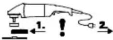
Pull the plug out of the socket before making any adjustments, converting or servicing the machine.
A damaged or cracked additional handle must be replaced. Never operate a machine with a defective additional handle.
A damaged or cracked safety guard must be replaced. Never operate a machine with a defective safety guard.
Do not switch on the machine if tool parts or guard devices are missing or defective.
ENGLISHen
Machines with a soft start (indicated by "WE" in the model designation): An electronic error occurs if the machine accelerates to maximum speed very quickly when switched on. Other safety-related electronic functions are no longer available. Have the machine repaired immediately (see 12.).
Secure small workpieces. For example, clamp in a vice.
When using dual-purpose (combined grinding and cut-off wheels), only the following guard types must be used: type A, type C. See chapter 11.
Using the correct guard:
Using an incorrect guard can lead to loss of control and serious injuries. Examples for incorrect use:
- when using a type A guard for lateral grinding, the guard may interfere with the workpiece causing poor control.
- when using a type B guard for cutting-off operations with bonded cut-off wheels, there is an increased risk of exposure to emitted sparks and particles, as well as exposure to wheel fragments in the event of a wheel burst.
- when using a type A, B, C guard for cutting-off operations or lateral grinding in concrete or masonry, there is an increased risk of exposure to dust and loss of control resulting in kickback.
- when using a type A, B, C guard with a wheel-type wire brush with a thickness greater than the maximum permitted thickness, the wires may catch on the guard leading to breaking of the wires.
Always use the matching guard for the accessory. See chapter 11.
Reducing dust exposure:

WARNING - Some dust created by power or sanding, sawing, grinding, drilling, and other
construction activities contains chemicals known to cause cancer, birth defects or other reproductive harm. Some examples of these chemicals are:
-
Lead from lead-based paints,
-
crystalline silica from bricks and cement and other masonry products, and
-
arsenic and chromium from chemically treated lumber.
Your risk from these exposures varies, depending on how often you do this type of work. To reduce your exposure to these chemicals, work in a well-ventilated area, and work with approved safety equipment, such as those dust masks that are specially designed to filter out microscopic particles.
This also applies to dust from other materials, such as some timber types (like oak or beech dust), metals, asbestos. Other known diseases are e.g. allergic reactions, respiratory diseases. Do not let dust enter the body.
Observe the relevant guidelines and national regulations for your material, staff, application and place of application (e.g. occupational health and safety regulations, disposal).
Collect the particles generated at the source, avoid deposits in the surrounding area.
Use suitable accessories for special work. In this way, fewer particles enter the environment in an uncontrolled manner.
Use a suitable extraction unit.
Reduce dust exposure with the following measures:
- do not direct the escaping particles and the exhaust air stream towards yourself or nearby persons or towards dust deposits,
- use an extraction unit and/or an air purifier,
- ensure good ventilation of the workplace and keep it clean using a vacuum cleaner. Sweeping or blowing stirs up dust.
- Vacuum or wash protective clothing. Do not blow, beat or brush protective gear.
5. Overview
See page 2.
1 " Quick " clamping nut *
2 S u p p o r t f l a n g e *
3 Spindle
4 W A...: Autobalancer support flange (non-detachable) *
5 Spindle locking button
6 Electronic signal indicator
7 Handl e
8 Lock (to prevent the machine from being switched on unintentionally, or for continuous operation)*
9 Trigger (for switching on and off)
10 Button (to turn the main handle)
11 Main handle
12 Additional handle/Additional handle with vibration damping
13 Safety cover
14 Adjusting nut *
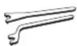
15 2-hole spanner
16 Quick-release clamp (to adjust safety guard without the use of tools)
17 Screw (to adjust clamping force of quick-release clamp)
- depending on equipment/not in scope of delivery
6. Commissioning

Before plugging in, check that the rated mains voltage and mains frequency, as stated on the label, match with your power supply.

Always install an RCD with a max. trip current of 30mA upstream.
Use only extension cables with a min. cross-section of 1.5mm^2 . Extension cables must correspond to the power consumption of the machine (cf Technical Specifications). If a cable roller is used, always roll up the cable completely.
6.1 Attaching the additional handle

Always work with the additional handle (12) attached! Manually screw in the additional
handle securely in the left, centre or right threaded hole (depending on requirements).
6.2 Attach the safety guard
Prior to operation: Attach safety guard.
For safety reasons, only use the guard provided for the respective accessory! Using an incorrect guard can lead to loss of control and serious injuries. See also chapter 11. Accessories! See illustration F on page 2.
- Open quick-release clamp (16). Mount the safety guard (13) in the position indicated.
- Turn the safety guard until the closed section is facing the operator.
- Close quick-release clamp.
- If necessary, increase clamping force of quick-release clamp by tightening the screw (17) (with opened quick-release clamp).
Use only accessories that are covered by at least 3.4mm by the safety guard.
6.3 Pivotable main handle

Only work with the main handle (11) engaged. See illustration C on page 2.
- Push in the button (10).
- The main handle (11) can now be turned 90^ to both sides and can be engaged.
- Make sure that it is securely positioned: the main handle (11) must be engaged and it should not be possible to move it.
6.4 Power-supply connection
The mains sockets must be protected using timedelay fuses or circuit breakers.
Machines with "WE..." in the model designation: (with inbuilt automatic startup-current limitation(soft start).) The mains sockets can also be protected using fast-acting fuses or circuit breakers.
7. Attaching the grinding disc

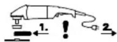
Prior to any conversion work: Pull the mains plug from the socket. The machine must be bed off and the spindle at a standstill.

For reasons of safety, attach the parting guards before performing parting work (see chapter 12 accessories).
7.1 Locking the spindle

Press in the spindle locking button (5) only when the spindle is stationary!
- Press in the spindle locking button (5) and turn the spindle (3) by hand until the spindle locking button engages.
7.2 Placing the grinding wheel in position
See illustration D on page 2.
Machines with the designation W 2..., WE 2...
- Fit the support flange (2) on the spindle. The flange should not turn on the spindle when properly attached.
- Position the grinding wheel on the support flange (2) as shown in illustration D.
The grinding disc must lay flat on the supporting flange.
Machines with the designation W...A 2....

The Autobalancer support flange (4) is permanently fitted on the spindle. As is the with most other angle grinders, a detachable port flange is not necessary.

The contact surfaces of the Autobalance support flange (4), grinding wheel and the k -Stop adjusting nut (1) or other adjusting nut must be clean. Clean if necessary.
- Place the grinding wheel on the Autobalancer support flange (4). The grinding wheel must lie flat on the Autobalancer supporting flange.
7.3 Securing/Releasing the "Quick" clamping nut (depending on features)

Securing the "Quick" clamping nut (1):

Do not use the "Quick" clamping nut if the accessory has a clamping shank thicker than 8. In this case, use the clamping nut (14) with 2-spanner (15).

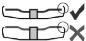
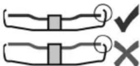
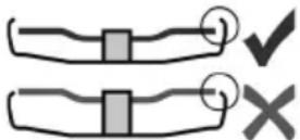
Only use the "Quick" clamping nut when undamaged and in perfect operating condition: the arrow must point to the notch on the ring (see illustration on page 2).
- Lock the spindle (see chapter 7.1).
- Fit the "Quick" clamping nut (1) on the spindle (3). See illustration on page 2.
- Tighten the "Quick" clamping nut by turning clockwise by hand.
- Turn the grinding wheel firmly clockwise to tighten the "Quick" clamping nut.
For machines with the designation W...B... an increased resistance is to be felt on the last 180^
Releasing the clamping nut (1):
- Lock the spindle (see chapter 7.1).
- Turn the "Quick"clamping nut (1) anticlockwise to unscrew.
7.4 Securing/Releasing the clamping nut (depending on features)
Securing the clamping nut (14):
The 2 sides of the clamping nut are different. Screw the clamping nut onto the spindle as follows:
See illustration E on page 2.
- A) For thin grinding discs:
The edge of the clamping nut (14) faces upwards so that the thin grinding disc can be attached securely.
B) For thick grinding discs:
The edge of the clamping (14) faces downwards
ENGLISHen
so that the 2-hole nut can be attached securely to the spindle.
- Locking the spindle. Turn the clamping nut (14) clockwise using the 2-hole spanner (15) to secure.
For machines with the designation W...B... an increased resistance is to be felt on the last 180^
Releasing the clamping nut:
- Lock the spindle (see chapter 7.1). Turn the clamping nut (14) anticlockwise using the 2-hole spanner (15) to unscrew.
8. Use
8.1 Switching On and Off

Always guide the machine with both hands.

Switch on first, then guide the accessory towards the workpiece.

Avoid inadvertent starts: always switch the tool off when the plug is removed from the socket or if there has been a power cut.

In continuous operation, the machine continues running if it is forced out of your box. Therefore, always hold the machine with hands using the handles provided, stand freely and concentrate.

Avoid the machine swirling up or taking in dust and chips. After switching off the machine, place it down when the motor has come to a dstill.
See illustration A on page 2.
Torque activation
Switching on: Slide the lock (8) in the direction of the arrow and press the trigger switch (9).
Switching off: Release the trigger switch (9).
Continuous operation (depending on features)
Switching on: Slide the lock (8) in the direction of the arrow, press the trigger switch (9) and keep it pressed. The machine is now switched on. Now slide the lock (8) in the direction of the arrow once more to lock the trigger switch (9) (continuous operation).
Switching off: Press the trigger switch (9) and release.
Machines with the designation W...B: Torque activation (with dead man's lever)
See illustration B on page 2.
Switching on: Slide the trigger switch (9) forwards and then push the trigger switch (9) upwards.
Switching off: Release the trigger switch (9).
8.2 Working Directions
Grinding:
Press down the machine evenly on the surface and move back and forth so that the surface of the workpiece does not become too hot.
Rough grinding: position the machine at an angle of 30^ - 40^ for the best working results.
Cutting-off operations:
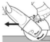
Always work against the run of the disc (see illustration). Otherwise there is the danger of the machine kicking back from the cut out of control. Guide the machine evenly at a speed
suitable for the material being processed. Do not tilt, apply excessive force or sway from side to side.
Sanding:
Press down the machine evenly on the surface and move back and forth so that the surface of the workpiece does not become too hot.
Wire brushing:
Press down the machine evenly.
9. Cleaning
Particles may become deposited inside the power tool during operation. This impairs the cooling of the power tool. Conductive build-up can impair the protective insulation of the power tool and create an electrical hazard.
The power tool should be cleaned regularly, often and thoroughly through all front and rear air vents using a vacuum cleaner or by blowing in dry air.
Prior to this operation, separate the power tool from the power source and wear protective glasses and suitable dust mask. Ensure appropriate suction is available when blowing out vents.
Button (10) for adjusting the handle: Occasionally blow compressed air through the button (when pressed, in all 3 main handle positions). Prior to this operation, separate the power tool from the power source and wear protective glasses and dust mask.
10. Troubleshooting
Machine with "WE..." in the model designation:
- Overload protection: The electronic signal display (6) lights up and the load speed decreases dramatically. The motor temperature is too high! Run the machine in idling until it cools down and the electronic signal display switches off.
- Overload protection: The electronic signal display (6) lights up and the load speed decreases slightly. The machine is overloaded. Work with a reduced load until the electronic signal display goes out.
Electronic safety stop: The electronic signal display (6) lights up and the machine was SWITCHED OFF automatically. If the slew rate of the current is too high (for example, if the machine suddenly seizes or kickback occurs), the machine switches off. Switch off the machine at the trigger switch (9). Switch it on again and continue to work as normal. Try to prevent the machine from seizing. See Section 4.2. -
Restart protection: The electronic signal display (6) FLASHES and the machine does not start. The restart protection is active. If the mains plug is inserted with the machine switched on, or if the power supply is restored following an interruption, the machine does not start up. Switch the machine off and on again.
-
When switched on, the machine accelerates to maximum speed very quickly, i.e. automatic restriction of the starting current does not work (soft start). An electronic error exists. Other safety-related electronic functions are no longer available. Have the machine repaired immediately (see 12.).
W 22-180 MVT, W 22-230 MVT, W 24-180 MVT, W 24-230 MVT, W 26-180 MVT, W 26-230 MVT: - Switching on the machine reduces the voltage briefly. Unfavourable mains power conditions may have a detrimental effect on other machines. Power impedances less than 0.2 ohm should not cause malfunctions.
11. Accessories
Use only genuine Metabo accessories.
Use only accessories which fulfil the requirements and specifications listed in these operating instructions.
Fit accessories securely. Secure the machine if it is operated in a bracket. Loss of control can cause personal injury.
See page 4.
Always use the suitable accessory and the prescribed guard for the matching guard for
the application. See page 5. (Illustrations are examples).
Application:
1 = surface grinding
2 = cut-off grinding
3 = drilling of holes
4 = wire brushes
5 = grinding with sanding paper
Accessories:
1.1 = grinding wheel
1.2 = cup wheel (ceramic)
2.1 = cut-off wheel "metal"
2.2 = cut-off wheel "masonry/concrete"
2.3 = diamond cutting disc "masonry/concrete"
2.4 = dual-purpose diamond cutting discs (combined grinding and cutting disc)
3.1 = diamond drill bits
4.1 = wheel brush
4.2 = cup brush
5.1 = flap disc
5.2 = backing pad for sanding sheets
prescribed guard:
Type A = cutting guard
Type B = guard for grinding
Type C = guard for grinding and cutting-off operations (combination)
Type D = guard for cup wheel
Type F = extraction guard for cutting-off operations
Other accessories:
(see also www.metabo.com)
A Bench cut-off stand
B Adjusting nut (14)
C "Quick" clamping nut (1)
For the complete range of accessories, see www.metabo.com or the main catalogue.
12. Repairs
Repairs to electrical tools must be carried out by qualified electricians ONLY!
A defective mains cable must be replaced only with a special, original mains cable from Metabo available from the Metabo service.
For machines with the designation W...B... the braking pad also needs to be replaced when replacing the carbon set.
Contact your local Metabo representative if you have Metabo power tools requiring repairs. For addresses see www.metabo.com.
You can download a list of spare parts from www.metabo.com.
13. Environmental Protection
The generated grinding dust may contain harmful substances. Dispose appropriately.
Observe national regulations on environmentally compatible disposal and on the recycling of disused machines, packaging and accessories.
Only for EU countries: Never dispose of power tools in your household waste! In accordance with European Directive 2012/
19/EU on waste electrical and electronic equipment and its implementation in national legal systems, used power tools must be collected separately and handed in for environmentally compatible recycling.
14. Technical Specifications
Explanatory notes on the specifications on page 3. Changes due to technological progress reserved.
D_ =max.diameter of the accessory
t_,1 = . permitted thickness of clamping shank on accessory when using clamping nut (14)
t_,2 = . permitted thickness of clamping shank on accessory when using "Quick" clamping nut (1)
t_max,3 =roughing disc/cutting disc: max. permitted thickness of accessory
t_,4 = . permitted thickness of wheel-type wire brushes
M = s p i n d e
I =length of the grinding spindle
n_0 =no-load speed (maximum speed)
P1 =rated input power
P2 =power output
m = weight without mains cable
Measured values determined in conformity with EN 60745.
Machine in protection class II
AC Power
The technical specifications quoted are subject to tolerances (in compliance with the relevant valid standards).
A Emission values
These values make it possible to assess the emissions from the power tool and to compare
ENGLISHen
different power tools. Depending on the operating conditions, the condition of the power tool or the accessories, the actual load may be higher or lower. For assessment purposes, please allow for breaks and periods when the load is lower. Based on the adjusted estimates, arrange protective measures for the user e.g. organisational measures.
The grinding of thinner metal sheets and other workpieces with large surfaces that easily vibrate can lead to a significantly higher overall sound emission (up to 15 dB) than the sound emission values specified. The sound radiation of such workpieces should be prevented to the greatest extent possible by means of suitable measures, such as fitting heavy, flexible damping mats. The increased sound emission must also be taken into account when assessing the risk of noise exposure and selecting suitable hearing protection. Vibration total value (vector sum of three directions) determined in accordance with EN 60745: a_h,SG = Vibration emission value (surface grinding) a_h,DS = Vibration emission value (disc sanding) K_h,SG/DS = Uncertainty (vibration)
Typical A-effective perceived sound levels:
LpA =Sound-pressure level LWA =Acousticticpowerlevel K_pA,K_WA = Uncertainty

Wear ear protectors!
Notice originale
Voir page 2, figure F.
Voir page 2, figure C.
Voir page 2, figure D.
Voir page 2, figure A.
Voir page 2, figure B.
W 22-180 MVT, W 22-230 MVT, W 24-180 MVT, W 24-230 MVT, W 26-180 MVT, W 26-230 MVT:
W 22-180 MVT, W 22-230 MVT, W 24-180 MVT, W 24-230 MVT, W 26-180 MVT, W 26-230 MVT:
W 22-180 MVT, W 22-230 MVT, W 24-180 MVT, W 24-230 MVT, W 26-180 MVT, W 26-230 MVT:
W 22-180 MVT, W 22-230 MVT, W 24-180 MVT, W 24-230 MVT, W 26-180 MVT, W 26-230 MVT:
W 22-180 MVT, W 22-230 MVT, W 24-180 MVT, W 24-230 MVT, W 26-180 MVT, W 26-230 MVT:
W 22-180 MVT, W 22-230 MVT, W 24-180 MVT, W 24-230 MVT, W 26-180 MVT, W 26-230 MVT:
n0 =Tomgangsturtall (hoyesteturtall)
P1 =Nomineit effektopptak
P2 =Utgangeffekt
m = V e k t u t e
Måleverdier iht. EN 60745.
Maskin med beskyttelsesklasse II
Vekselström
W 22-180 MVT, W 22-230 MVT, W 24-180 MVT, W 24-230 MVT, W 26-180 MVT, W 26-230 MVT:
Reservedelsestiner kan downloads pa www.metabo.com.
W 24-230 MVT, W 26-180 MVT, W 26-230 MVT:
POLSKIpl
W 22-180 MVT, W 22-230 MVT, W 24-180 MVT, W 24-230 MVT, W 26-180 MVT, W 26-230 MVT:
He BkIIOuHaIe HNCTpyMeH TpH OTCyTCTBHN HIN NOBpeKdEHH erO deTaIe HIN 3aUHTbIX npncnoc6JIeHH.
MaunHbC nIaBbIM nyckom (c MapnpoBkoN "WE..." Ha TINOBO TaBnueKe): Ecn np3anucke MaunHa Oeyh6bICTPO yCKopaeTcdo MaKcImaJIbHOJyactOTbI BpaueHn,TO IMeET MeCTO Own6Ka B 3JeKTPoHHOM 6LoKe. Dpyrne Yka3aHnno TExHNKe 6e3OpacHocTH OTHOCTeJIbHO FyHKUIN 3JeKTPoHHOro 6L0Ka He npIBoAraTc. HEmdLenHo CdaTe 3JeKTPoHHCTpymeHT B peMOHT (CM. rnaby 12.).
3aKpeIJIeTe He6OJIbUJne 3aROTOBKn, HApPIMep, 3aHMaIte IN B TnCKax.
Pn HcNoB3OBaHn yCTaHaBJIbNAeMbIX Ha
fHaIae KpyROB DBOHORO nPnMeHeHn (KpyROB
Jra WInΦoBaHn I a6pa3NBHO pe3KN) MOxHo
PnpMeHrTb 3aunTHbIE KOxHyN ToIbHO TnA A N C.
Cm. rnaBy 11.
IcnoJIb3yIte COOTBeTCTByIOUm 3aunTHbI KOHyX:
Ecn He nCnOJb30BaTb COOTBETCTByUoyni 3aunTHbI KOKyX,3TO MOKeT npNBecTN K NOTEpe KOHTpOJI HaI INHCTpyMeHTOM I cepBe3HbIM
TpaBMaM. IprnMepbI He npBaHJIbHOrO NcNoJIb3OBAHn:
- npn HcnoB3OBAHnn 3aunTHoro KOxhyxa Tnna A Dnla WnHΦOBAHnT Opuom Kpyra 3aunTHbI KOKyX MOKeT CToJKNHyTbcR C 3aROTOBKo, YTO BeDeT K HeoCTaTOHOMy KOHTPOIO.
- npn nCnoJb3OBAHnn 3aunTHoro KOKyxa Tnna B npn a6pa3NBHO pe3Ke yCTaHOBJIeHHbIM OTpe3HbIM KpyROM BO3HnKaeT ONaCHOCTb BbIbPOca NCKpN OTOJINΦOBaHHbIX YactNu, a TaKHe OCKoJKB WJINΦOBaJIbHOrO Kpyra B Clyuae erO pa3JaMbIBaHn.
- npn HcnoB3OBAHn 3aunTHoro KOxhya Tnna A, B, C npn a6pa3NBHO pe3Ke n uinfoBaHn TopoM Kpyra 6eToHa nn KnpnHOn KlaKn BO3HNKaET NOBbIeHHa ONaCHOCTb BCJeDCTBne Bblpoca nbIn, a TaKHe BCJeDCTBne NOTepn KOHTPOJHaINHCTpyMeHTOM,pe3yJIbTaTOM yeRo YBJIeTcER oTO DaVa.
- npn HcnoB3OBAHn 3aunTHoro KOHyxa Tnna A, B, C tapeIbYaToI ueTko, ToIuHa KOTopoN 6oJIbwe DoNyCTUMoN, nPOBOLOKa MoKeT KaCaTbCra 3aunTHoro KOHyxa, N 3TO npNBODNT K 06pbIBAHNO npOBOLOKn.
Bcerda nCnoIb3yIte noXoJusn dIpa6OerO HNCTpyMeHTa 3auTHbI KOxIyxC.M. rIaby 11.
CHINHEHNE nblJeBOH Harpy3HN
A NPEyPExEHEHNE. IbIb,
O6pa3OBaBsaJcB pe3yIbTaTe ⅢnΦOBKn HaKaDaUHOb 6yMaRo, paCnINiBaHn, ⅢnΦOBKn, CBepHeNn I DpyrNX BnDOb pa6oT, MoKET CODepKaTb XmMueChne BeuEcTBA, O KOTOpbIX N3BeCTHO, YTO OHN Bbl3bIBaHT PaK, BPOKeHHbIe DeΦeKTbI INn DpyrNe NOBpeKDeHnR pePnoDyKTHBHO CnCTembl. PpImepbl TaHX XmMuecknx BeuEcTB:
CBNHueB KpaChe C COdepKaHnem CBNHua;
-MHepaIbHaN PbIb OTCpOnTeIbHOrO KInPnUa, cEmeHTa N DpyrNX BeuEcTB KInPnUHo KlaAKn;
- MblbHK XpOM N3 XHMnueckN O6pa6oTaHHoI DpeBecnHbl.
CTeeneb pncKa 3aBnCnT OT TO, KaK qacto Bbl BbINOJIHReTe 3OT BnD pa60t. YTO6bl yMeHbIHTb BO3dEChTBnE XIMNueCKnx BeIeCTB, pa6OtaIe TB NOMEuEHnX C DOCTaTOUHO BEHTIaIcnei n C IcNOJb3OBaHnEM pa3peWeHHbIX CpeIcTb INHDbNyAlbHO 3aUNrbl, HApPmep, C pecnnpaTopamn, pa3pa6OtaHHbIMn CneuaIbHO Dlan FInbTpaun MKNpocOnnueCKnx YaactNu.
3TO TaKHe KacaetcNbIIN OT dpyrnx MaTePnaIOB, HAnpIMep, HeKOTOpbIX BnIOB dpeBeCnHbI (dpeBeCha Nblb Dy6a nn 6yHa), MetaIIa, ac6ecTa. PyrHe n3BeCThBie 3abOJIeBaHnra — 3TO, HAnpIMep, aJIeprHueckne peakun, 3abOJIeBaHnra DblxATElbHbIX nyTei. He DonyckaTe nonadHnra Nbln BHyTpboPaHn3Ma.
Heo6xOIMO CO6IIOaTb Tpe6OBaHnN DnpeKTHB, DeiCTByUOuNX BOTHOWeHn MaTePnaJIOB, nepcoHaJa, BapnaHTOB npImeHnN MeCT npoBeDeHn pa60T, a TaKHe HaOnHaJIbHbIe npednCaHn (HaNPmep, pIoJKeHnO6 OxpaHe Tpyda, npabnla yTnIn3aun).
Obecneyte ydaJIeHne o6pa3yUOxNcY qAcTnC, He donyckaIte o6pa3OBAHnO TIOJKeHnB OKpykaIoUeM npoctpaHCTBe.
Дяспаьнбix pa6OT nCNoIb3yIte NOxOJaIyIO OChAcThy. 3TO nO3BOJNT COKpaTHTb KOJIYeCTBO YacTHU, HeKOHTpOJIpyeMo Bbl6pacbIbAeMbIX B OKpyKaIOU cyIy.
IcnoIb3yIte nOxOJaUe yCTpoiCTBO ydaJIeHnIbIIN.
ДяУMeHbSeHЯпbleBoH Harpy3Kn DeJaNTe CLeDyUoUee:
-He HanpaBnIte BbI6paCbIbAeMbIe n3 3JIeKTPoHnCTpyMeHTa YacTnCbI NOTpa6OtaHHbI BO3DyX Ha Ce6R, HaxOJaUnxCpRdOM JIODei NNHa CKONJIeHNIpbII.
- IcnoIb3yIte BbITaHHOe yCTpoIcTBO n/nn BO3dyXOOHcTHeJIb.
- xopowo npoBETpnaIte pa6ooye MeCTO n COepeHnTE eRO B YNCTOTE C NOMOuBo NbJIeCOca. POnMeTaHne HIN pOyBkA TOLbKO NOHNMaHT PbIbB BO3dYx.
- 06paTaBbAaTe 3aunTHyU OeJy NblneCOCOM
HIn CTnpaIte. He npOdyBaIte OeJy
BO3dYxOM, He BbIbNbaIte HcMeTaIte C Hee
PiJIb.
5.0630p
Cm. c. 2.
1 3aKHMHraIka Quick *
2Подерживаюший Фланец*
3Unnndelb
4 WEA....POndepKnBaHouuNΦlaHeu abTo6aHaHCnpa (HeCbeMhB)
5KhoNka cTOnopaIHHdJIa
6 ΘлектpoHHbI CNHаньИинДИКaTOp*
7PyKoTHa
8 BLOKHPaTOp (JIA 3aUNTbI OT CnyauHORO BKIOUChENr/aKTINBn3aun HEnpepbIBHORo peKIMpa60TbI)
9 HaKIMHOI nepeKIOUaTeIb (DJIY BKIIOUeHn/ BBIKIOUeHn)
10 KHonka (Дя рergyларови ochobhoу pyKoTkn)
11 OchoBna pyKoTHa
12 DOnOHnTeIbHa pyKoTka/DoOnHnTeIbHa pyKoTka C rAweHem Bn6paun
13 3aunTHbI KOJyX
14 CTaXHbIe raIKN*
15 DByXwTnΦTOBbI KJIouc
16 3aueIka (IJIpeRyIINPOBKN 3aUHTHOKOKyxa 6e3 INHCTpyMeNTa)
17 BnHT (IJIpeRyIpOBKn 3aJHMHO yCNIJIa 3aueJIKN)
*B3aBNCIMOCHTO KOMJIeKtauu / He BXoNT B KOMJIeKT NOCTaBKN
6. BBOD B 3KcPnyatauio
IpeD BBODOM B 3KcNlyaTaunIO npOBepbTe, COBnaDAHOT Jn yKa3aHHbE Ha 3aBOdCKOJ
Ta6nueKe 3NaeHnHa npJKeHn HacTOb CetN CnapaMeTpamn 3JeKtpocetN.
PYCCKHru
IpepeHnHCTpyMeHToM BcerdaNoKJIIOuayTe aBTOMaT 3aUHTbI OT ToKa yTeuKN (Y3O) c MaKC.TOKOMOTKJIIOUeHn30MA.
IcnoJIb3yInTe ydHnHtBbHbI Ka6eIb C MNHmAlhBbIM CeueHem 1,5 MM². YdHnHtEJbHbIe Ka6eJIN DoJIHXbI COOTBeTCTBOBaTb NOTpe6JIeMoM MOUHOCTN IHCTpyMeHTa (cp.TexHueckne xaKaTEpcnCTnK).PpN cNoJIb3OBAHN Ka6eJIbHOro 6apab6aHa Ka6eJIb CneDyeET PONHOCTbIO pa3MOTaTb.
6.1 YctaHObKa dOnoJIHHTeJIbHOpyKOrTKn
Pa6oTaHTe TOnbKO C yCTaHOBJIeHHoJ DOnOJIHnTeJIbHOpyKOrTko(12)! BBnHTnte DOnOJIHnTeJIbHyIO pyKOrTKy Do yNopa B JIeBOe, CpeDHee HnI npaBOe (B 3aBnCmOcTn OT NOTpe6HoCTn) pe3b6OBoE OTBepCTne n 3aTAHnTe OTpyKn.
6.2 YctaHOBka 3aunTHoro KOHyxa
IpeH hauanpa6oT: ycTaHOBnTe 3aunTHbI KOxYX.
H3 coo6paKeHn 6e30NaCHOCTN HCNoJIb3yIte TOnbKO TaKoN 3aUHTbI KOKyx, KOTOpB IpeDyCMOTpeH dIa COOTBeTCTByUOepo paOoeryo HNCTpyMeHTa!EcNI He NcNoJIb3OBaTb COOTBeTCTByUOuN 3aUHTbI KOKyx, 3TO MOKeT npNBecTN K NOTepe KOHTpOJa HAd INHCTpyMeHTOM n cepBe3HbIM TpaBMam. Cm. TaKHe rIaby 11. "PpHaJdJeKHOCTn"! Cm.pncyHok F Ha c.2.
- OTKpoIe 3aueJky (16). YcTaHOBInTe 3aUHTbIy KOKyx (13) B NOKa3aHHOM NOLOXHeHn.
-ПовернITEЗаштейньй кожух тakIMобра3OM,УTOбы erOЗakpbITaя 3OHaбILA obpaцehaКВam. - 3aKpoITe 3aUeJIky.
-При Heo6xOДMOCTo, yBelenuYe 3aJHmHoE yCnIe 3aUeJIKN, 3aTyrHyB BnHT (17) (prn OTKpbIToN 3aUeJIKe).
HcnoJb3yIe ToIbKO Te pa6oue HNCTpyMeHTbl, KOtOpBle BbICTyNaIOTn3-NOd 3aunTHoro KOKyXa He 6oJee, Yem Ha 3,4 MM.
6.3 Поворотна OCHOBHЯ pyKoTHa
Pa60TaIe TOJbKO C 3aΦHKCnPOBaHHoN OCHOBHOpyKoTko(11).
CM.pncyHOKCHa c.2.
- HaKmTe KhoNky (10).
- Tenepb OCHOBHyIO pyKoTky (11) MoXHO NOBepHyTb B o6e CTOpOHbI Ha 90^ n 3aФнКсИрВaTb.
- PpOBepbTe npOuHOCbI NOCaADn: OCHOBHa pyKoAHTKa (11) DOJIHHa 6bITb 3aΦHKcnpOBaHa n He DoJIHHa npOBopauHBaTbCra.
6.4 IopKIOUeHne K cETn 3/NTaHna
CetebIe wTeNCEJIbHbIe po3eTKn DOJIHHbI 6bITb 3aunueHb INHePcUNOHbIMN PnabKIMM
PpeOxApaHnTeJMaHm Hnn JInHeHbIMN 3aUHTbIMN aBTOMaTAMN.
MaunHbIcMapKnpOBHO"WE..."HaTINOBO Ta6nue: (co BCTPOeHHbIM aBTOMaTHueCKM OrpaHnHTeJIem NyCKOBOro TOka (fynKcnnei PnABHOrO nycKa)) CeTeBbIe wTeNceJIbHbIe p03ETKn DOJHKhbl 6blTb 3aUuIeHbl INepCuOHbIMn PnabKHMn PpeDOxpaHNTeJIam INI JInHeHbIM 3aUHTbIMn aBTOMaTaMn.
7. yctaHOBka a6pa3HBHOro Kpyra
Ipeed IIO6oI nepeHaiaKo: N3BLeKeHTeTeByIO BnIKy n3 po3eTK.NHCTpyMeHTdoJHKEN HAXOINTBcB B BbIHIOUeHHOM COCTOHN, a WnHdJIb DOJIKeH 6bITb HeNOdBnXHBIM.
Дя pa6ot C OTpe3HbIMN Kpyramn B ueJx 6e30naCHOCTN HcNoIb3yIte CneuaJIbHbie 3aunTHbIe KOxyN DЯ OTpe3HOrO Kpyra (CM. rIaby 11. PnHaadJeKHOCTn).
7.1Фнcaишпндя
KhONky cTOnopa WnHdJIe (5) MoXHO haXIMaTb TOLbKO npn HEnoDBNKHOM WnHdJIe!
- HaKmTe KhONky cTOnopa shnHdJIe (5) n KpyTnte wHHdJIb (3) ot pyKn do Tex nop, noka KhoNka cTOnopa shnHdJIe OuyTMo He 3a6loKnpyETc.
7.2 YctaHOBka a6pa3nBHorO kpyra
CM. pncyHok D ha c. 2.
MaunHbI c MapKnpOBkOw W 2..., WE 2...
- YctaHOBnTe NOdepKINBaIOUmI ΦlaHeu (2) Ha UINHDeJIb. ΦlaHeu yCTaHOBJIeN IpaBnJIbHO, ecIn OH He npOBOpauHBAeTcRa HA WnIHDeJIe.
- YcTaHOBnTe a6pa3nHBn Kpyr, KaK nOKa3aHo Ha pncyHke D,Ha noDdepKnBaIOuSniΦlaHeU (2). A6pa3nHBn Kpyr DoJIKeH paBHomePno npIneRaTb K noDdepKnBAIOuEMyΦlaHcy.
Maunhbc MapKnpOBKn WEA 2...
NoepKnBaUHmΦaHeu aBTo6aHaCnpa (4) JeCTKO KpeNTcHa WnHdene.3TO O3Haayet,TO,BOTINue OT dpynx yIIObIX WlnΦMaunH, He Tpe6yeTc DOIOJIHnTeJbHbI CbeMhbl NoepKnBaUHmΦaHeu.
I NobepxHocTH NOdEepKnBaHooJero FJIaHua (4) aBTOb6aHaHCnpa, abpa3NBHOrO Kpyra n 3aHHMOH raIKN Quick (1) INN 3aHHMOH raIKN (14)doJIHKbI 6bITb YnCTbIMN. PpHHeoXoDMOCHT Nx HJHKHOPOHCTNTb.
- YctaHOBHTe a6pa3nBbHbKpyrHa NOdepHHBaOuNΦlaHeC(4) aBTo6aJAHcnpa. A6pa3NBbIKpyrdoJIKeH paBHOMepHo npIneratb KΦlaHcy aBTo6aJAHcnpa.
7.3 KpenIeHne/OTBnHcNbHaHne 3aKHMHO raIKu Quick (B 3aBNCmOCTn OT HOMJIeHTaUN)

HpenIeHne 3aHHMHOraHn Quick (1):

EcnToIiHa pa6Oero HNCTpyMeHTa B 0bIactn 3aKIma IpeBbIaeaT 8 MM, 1b3OBaHne 3aKIMHOraKn Quick eueHo! B 3tOM clyuae HcNoJIb3yIte raHy C DByXWTnΦTOBbIM KInOcHm (15).

IcnoJb3yIte TOLbKO HeNoBpeKdEHHyU 3aHmHyO raHy Quick: cTpeJIka DoJIKHaa bIBaTb Ha BbIeMHy HapyHHO KOJIbua (CM. CTp.2).
- 3aФИКСИРУТЕ ШПИНDEЛь (CM. ГЛаву 7.1).
- HacaIte 3aKIMHyO raIky Quick (1) Ha IINHeJIb (3). Cm. pnc. Ha c. 2.
-Pyko3aTAHHTe 3aHmHyIO raHy Quick no YacobOcTpeJIke. - 3aTaNHTe rAky Quick no yacobO CTpeJIKe, cnIbHO NOBepHyB a6pa3NBHbIKpyr.
Y MaunH C 603NaueHem W...B... Ha nocJeHnx 180^ DoJxHO yBCTBOBaTbcra NObIiHeHHoe COnpOTnBJIeHne.
OTBHHyBaHHe 3aJHHMHOraIKN Quick (1):
- 3aФнКсИрУTe WIIINHДeь (cM. rIaBy 7.1).
- OTBnHTnte 3aKIMHyo raHy Quick (1) npotNB YacOBON CTpeKN.
7.4 KpenJIeHHe/OTBnHcNbAHne 3aKHMHOI raIKN (B 3aBNCMOCTH OT KOMJIeHTaUH)
Hpenenne (14) 3aXHMHO raHn:
DBe CTOpOHbI 3aJHMHOn rAaN OToJIuHaOTcR dpyr OT dpyra. HABnHTnte 3aJHMHyO raKy Ha WnHdJIb B CJeDyUoE M nopAKe:
CM. pncyHok E Ha c. 2.
-A)ДЯToHHx a6pa3nBbIx KpyROB:
TTO TOTO6bMoKHO 6blHO HadeKHO 3aKaTb TOHKn a6pa3nBHyk Kpyr, 6ypTN 3aHHMHO raKn (14)doJKeH 6bITb HanpaBJeH BBePx.
B)ДЯTOJICTbIXa6pa3HBHbIXHpyROB:
TTO TO6bMOHHO 6bIIO HaJeHHO HABnHTNb 3aKHMHyO rAky Ha IINHeIb, 6yptNK 3aKHMHO rAkn (14)doJKeH 6bITb HnpaBLeH Bn3.
-3aΦnKcnpyIe IINHdJIb.3aTAHnte 3aKIMHyO raNky (14) c NOMOsbIO DByXHToTOBOrO KJIoua (15) no yacoboi cTpeJIke.
Y MaunH C 6o3HaueHem W...B... Ha nocJeHnx 180^ DoJxHO yBCTBOBaTbcra NOBbIeHHoe COnpOTnBJIeHne.
OTBHHUBAHHe 3aJHMHOraKn:
- 3aФИСИРУТЕ WIINHДELь (cM. rIaBy 7.1). OTBИNTHTe 3aЖIMMHyIO raIky (14) c NOMOцьIO DByXHTNΦTOBOrO KJIIOVA (15) npOTnB YacOBoi CTpeJKN.
8.Зкплуатацья
8.1 BkIIOueHHe/ByIKIOueHHe
HCTpyMeHT Heo6xOaMo Bcerda DepeKaTb oBeMN pyKaMn.
I OIOBODNTe HNCTpyMeHT K 3aROTOBKe TOJIbKO BO BKJIHOeHHOM COCTOAHIN.
He donyckaTe HnpeHaMepeHHoro 3anycka: Bcerda BBklnouaTe INHCTpyMeHT, ecnBnIka 6bila n3BLeueHa n3 po3eTKn nnecn npon3oWeJ c60B B noDaue 3JeKtpo3Heprnn.
BpeKHe HepepebIBHOJ 3KcNlyaTaunn HNCTpyMeHT npoDoJIkaeT pa60TaTb, DaKe ecn OH BbIPBeTcH 3pKN. PoToMBy CceIa KpeKN DEpKHTe INCTpyMeHT DByM pyKaMn 3a pyKoAHTH, 3aIMnTe yCTOuHBOE NOLOKeHne I NOLHOCTbIO CHOHcEHTPnpuyTEcB BbINOJIHReMOI pa6Ote.
He donyckaite 3abnxpeHnI INBcacbBaHHN IHCTpyMeHTOM nbIIN ctpyKn. He klaIte 3JeKTPoHnCTpyMeHT Do NOHOr OCTaHOBKn DBNrataJIeJ.
CM.pncyHOKAHa c.2.
HpaTHOBpeMeHHoe BKNIOueHne:
BkIIOueHHe: nepeDbINbTe 6IoKnpaTop (8) B HApBaBLeHn CTpeJKN HaKMITE nepeKnOyateJIb (9).
BbIKJIIOUeHHe:OTnycTnte HaKIMHOI nepeKIIIOuHaTeIb (9).
HenpepbBbHbI peXnMa60TbI (B 3aBnCmOCTn OT KOMnJIeKtauu):
BkIIOUeHHe:pepeBnHbTe 6IoKHpAToP (8) B HApPaBHeHn CTpeKn n HaKMnTe nepeKlIOuAteIb (9).3JeKtpOnHCTpyMeHT BkIIOUeH. TeNepb pepeBnHbTe 6IoKHpAToP (8) eue pa3 B HAppaBHeHn CTpeKn, YTObI 3a6IoKpOBA Tb HaKHMHOI nepeKlIOuAteIb (9) (peKm HeppepbIBHOI pa6oTbl).
BbIKIOueHHe:HaKMnTe NOTNcyCTNTe nepeKIOuATEIb (9).
HnctpymEnbI c 6o03haueHneM W...B: KpaTkoBpeMeHHoe BkJIIOUeHne (cФyHKuNei abTOCTOna)
CM.pncyHOKBha c.2.
BkIoueHne: nepeBnHbTe BnepeHaKHMHO npeKIOuataJIb (9), 3aTeM HaKHMHO HAKMITE BBepx nepeKIOUaTeJIb (9).
OTKIOUcHHe:OTNcyCTnTe HaXHMHOI nepeKIOuOaTeJIb (9).
8.2 Pa6oUne yHa3aHnA
UlnfoBaHne:
PnHKMaIte HNCTpyMeHCT C yMEpeHHbIM ycJIHem I nepeMeaTe erO NO NOBepxHOCTN B3aD IN BnepeD, YTO6bIOBepxHOCTb 3aROTOBKN He neperpeBaJacb.
YepHOBoe wIINΦOBaHHe: IJIЯ NOJUyeHnXopoWero pe3yIbTaTapa6oTaIteCycTaHOBOuHbIM yrIOM 30^ - 40^
PYCCKHru
A6pa3HBHOe OTpe3aHHe:
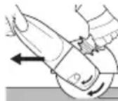
Pn a6pa3NBOM OTpe3aHnB CcERda pa6oTaIe BO BCTpeHOM HappaBHeHH (CM. pucyHok). NHaue HHCTpyMeHT MOKeT HeOHNDaHHO BbICKOHTb n3 npOnnla.Pa6oTaIe c
yMepeHHoIpoaYe, COOTBeTCTByIOUeI O6paBaIBaEMOMy MaTePnAly. He dOnyckaIte nepeKocA, He HaXImaIte N He paKaunBaIte NHCTpymEHT.
IInnoBaHne CnOJIb3OBaHHem HaJdaUHOI 6ymar:
PnKMaTe HNCTpyMeHCTyMEpeHHbIM yCINHeM nIepeMeaTe erO NO NOBepxHOCTn B3aN IN BnepeD, YTO6bIOBepxHOCTb 3aROTOBKn He neperpeBaJacb.
06pa6oTHa hapdoUeTHaMn:
ymepenHNO npnKmaiTe nHCTpymeNT.
9. OuInCTka
Pn pa6Ote BO3MOxHcKoJIeHHe yactnuc
obpaTaBIAEMORo MaTePnaJa BHyTpN
3NeKTponHCTpyMeHTa. 3To yXyDwaet
OXlaKeHHe N3NeKTponHCTpyMeHTa.
TokopobOJaune cKoJIeHnMOryT HApuyuNTb 3aUHTHyU N3OJIaCNIU 3JeKTpONHCTpyMeHTa, YTO COnpJKeHO C ONaCHOCIO npaKeHn 3JeKtpNueCKHM TOKOM.
Yepe3 He60JIbUHe paBHbIe npOMeKHTKn BpEmEH TtateJIbHO ydaJIaTb 3aIrp3HeHnI N3 nepeDnIX N 3aDHNX BEHTINLAuONHHbIX UeJIe
3JIeKTPoINHCTpyMeHTa IIN IpOdyBaTb INx CyXIM BO3dYxOM. PepeD 3TNIM OTcoEduHITe
3JIeKTPoINHCTpyMeHT OT HCTOCHNkA NITaHnA, a pRn pa60Te NCNoJIb3yIte 3aUHThIe OUYN I COOTBeTCTByIOUs peCnnpaTop. Ppi npOdyBKe DOJXHa 6bITb ObecneueHa DoCTaTOUHa BBITJHKHa BEHTINLAuNIA.
KhoHa (10) dnypeylnpoBnu pykOHTn: Pn HEO6xOIMOCTN ydaIaIyTe 3aIpy3HeHn I3 KHOHN IIIN pOdyBaIte ee cyXm BO3dyXOM (B HaKaTOM COCTOAHN, BO BCEX 3 NIOJKeHn OCHOBHOn pyKoTKn). IpePe 3TmM OTcoEHNHTe 3JIeKTPoHHCTpymeHt OT NCTOCHNka NITaHn I HocHTe pN tON 3aUHTbIe OUYn I peCnnpaTOP.
10. YcTpaHHe HEnCnPaBHOcteI
MaunHbI C MapKnpOBkOJ "WE..." Ha TnIOBOJ Ta6nUKe:
-3aunTa OT neperpy3Hn: 3JeKtpoHHbI CNrHaNbHi INHdNkATOp (6) 3aropaeTcN Yactota BpaueHn NO Harpy3HOJ 3AMETHO ChnKaETc. NObblneHHaTeMnepaTypa DnRaTeJI! DaIte nopabotb 3JeKTPoHNCTpyMeHTy Ha XOIOCTOM XOy, nOKa OH He OCTbIHET IN He NorachET 3JeKTPoHHbI CNrHaNbHi INHdNkATOp.
-3aunTaOTneperpy3Hn:3JeHTPOHHbIN CNrHaNbHbI INHnKaTOp (6) 3aropaetcN Uactota BpaueHnnoh Harpy3HoCJELHA NOHNxAeTc.3JeHTPOINHCTpymeHT neperpyhen. PpOdoJIHkaTe paOtaTb C
NOHNKeHHoH HArpy3KoN, NOKa 3JeKToPOHHbI CNHaJIbHbI INDnKaTOP He NoraCHET.
-3JeHTPOHHOe abapnHoe OTKIOUOHe: 3JeHTPOHbI CNrHaJIbHbI INHdNkAtOp (6) 3aRopaETc, H MaunHa cAmOCToTeJbHO OTHJIOUaETc. Pn CInuHOM 6bICTpOM HapacTaHn TOKa (3TO pOnxCoDHT HaPmEp npBHe3aHNo 6IokHnpOBKe nIIN OTdaYe) 3JeHTPOHnCTpyMeHT OTKIOUaETc. BbIKIOUHTe 3JeHTPOHnCTpyMeHT HaKIMHBIM NpeKIOUaTelem (9). Pocne 3Toro erO cIeDyET CHOBA BKIOUHTb I npOdoJIKNITb pa6OTy B HopMaJIbHOM peKHMe. N36eraIte 6IokHnpOBKn B daJIbHeIWe.M. rIaby 4.2.
- 3auneta OT NOBTOPOHOro nycKa: 3JeKToPHbIcHraJIbHbI INHdINHaTOp (6) MInrAETn3JeKToPHOHCTpymeHT He pa6Otaet.
Cpa6oTala 3aunTa OT NOBtOPOHOro 3anycHa.
EcIn npn BkIIOUeHHOM INCTpyMeHT CeTeBaJ
BnIka BCTabJIeTcR Bpo3eTKy, INN NocLe C60r
BOcCTaHOBNeHa NODaCa 3JeKTPoNTaHIN,
INCTpyMeHT He 3anycKaeTcR. BbIKIOuHTe IN
CHOBa BkIIOUHTe INCTpyMeHT.
TnD=3aHTbI KoxyX IJIaIIIOBaJIbHOJ
TnF=BbITJHKHOJ3aUNTHbI KOKyXdJI a6pa3NBHOpe3KN
Bo3MOHHbIe npHnAdJeHxHocTH: (Cm. TaKHe caHT www.metabo.com)
A CToIka Ia pe3Km MeTaIIa
BCTaXHbIe raKn (14)
C 3aKHMHa raKa Quick (1)
Полны accopTUMeNT npHnAJIeJHKoCTe CMOTpIte Ha caIte WwW.metabo.com Ил В ГЛаВHOM KaTAlore.
12. PemoHT

K pemOHTy 3JIeKTpOHnHCTpyMeHTa DONYCKaIOTCra TOIbKO KBaIIINΦnICnPOBaHHbIE NaJIInCTbl-3JIeKTprNK!
NoBpeKdEHHbI CeTeBOKa6eJIb CJIeDyeT 3aMeHrTb TOnbKO Ha CNeUHaJIbHbI, OpiRnHaJIbHbI CeTeBOKa6eJIb Metabo,KOTOpbIMoJHO pnpO6pctN B cepBnCHOM ueHTpe Metabo.
Y MaunH C 06o3HaueHnem W...B... npn 3aMeHe KOMnJIeKTa yroJbHbIX UeTOK TaKHe CneDyET 3aMeHrTb TOPMO3HbIe HaKnAaKn.
CnNcKn 3aNaChbIX YacTei MoXHo cKaaTb C caYTa www.metabo.com.
13. 3auntata OKpyhaioe cpebl
O6pa3ykuocaraaIbnfoBaIbHaIbMOKeT coepKaTaB BpeHbIe BeueCTBa, NO3tOMy ee CneDeyET yTNIN3nPoBaTa HAdJeKaUIM 6pa3OM.
Co6IIOdaIte HaunOHaJIbHbIe npaBnla yTIN3aUN IN nepepa60TKN OTCnyKINBwero IHCTpyMeHTA, yNaKOBOK IN pInHaJdEJKHOCTeN.
ToIbKO dIaN cTpaH EC: He yTHIN3npyIte 3JIeKTPoHNcTpymEnTbI BMeCTe C 6blTOBbIMN OTXODAM! CorlaChO dIpeKTNBE EC 2012/ 19/EU no OTXoAM 3JIeKTPuYeCKoro n 3JIeKTPoHNHO6OpyDoBaHH N COOTBeTcTBkyUHm HaUHOHaIbHbIM HopMam 6blWne B yNOTpe6JIeHHN 3JIeKTPoPn6Opbl N 3JIeKTPoHNcTpymEnTbI NOJIeJHAT pa3dJIbHOYTHIN3aCNI C ceJIbIOHX NocJeDyIoSe I KOLOrHuCeCN 6e3OnaCHO nepepa6OTKn.
14. TexHnueckne xapaKTepeNCTnKN
IorcheHnKaaHHbIM,yKa3aHHbIM Ha c.3. OctabJIeM 3a co6oN npaboHaTexHnueckne n3MeHeHn.
Dmax =MaKc.ДиamEtpo pa6Oyero HnHCTpyMeHTa tMaKc.1 =MaKc.DOnyCTmMaJTOJIuHa pa6Oyero HnHCTpyMeHTaB DnHaNa3OHe 3aKIma npN HCNoJIb3OBaHHN 3aKIMHOJraIKN (14)
t_max,2 = MaKc. ДуСТМАЯТOLИнha pa6Oчero HCTpyMeHTa B O6JIaCTn 3aЖИма пи HcNoIb3OBAHIn 6bICTpo3aЖИMHOn raJKN Quick (1)
t_max,3 = Kpyr Дя черноюшлфовань/ OTpe3Hoi Kpyr: MaKC.ДОпустимаяТолцина paбочero INHCTpyMeHTa
P2 =BbIXOHaMAOuHOCTb
m =Macca 6e3 cTeBOrO Ka6eJra
Pe3yIbTaTbI n3MepeHn noJyHeBb COOTBeTcBnco cTaHapToM EN 60745.
HnctpymEnKlacca3aunTbI I \~ nepemehhbi TOK
Ha yka3aHHbIe TexHnueckne xapaKTepeNTKN pacnpoctpaHIOITc DOnyCKN, npdeYCMOTpeHHbIE DeiCTByIOUIMN CTaHdApTaMn.
3HaueHn 3Mnccn Wyma
3Tu 3HaueHn IO3BOJIO T OeHNBaTb N
CpaBnBaTb 3MnCCnIO Wyma pa3NHybIX
3LeKTPoHHCTpyMeHTOB. B 3aBnCmOcTn OT
ycNoBn 3KcnIyatauH, COCTOHN
3LeKTPoHHCTpyMeHTa HnPa6OuHX INCTpyMeHTOB
fAKTnuecka Harpy3Ka MOKeT 6bITb BblIe HnHKe. DnOeHNn PnIMepHO rpoBHr 3MnCCn
yUHtBaHte NepepbIBbB bPa6Ote H fAsbI Pa6OtBc C
NOHNHeHn (WymoBOH) Harpy3KoN. OnpeDeJInte
nepeYeHb OpraHn3aunOHbIX Mep No 3aunTe
10Nb3OBaTeJIc C yyeTom Tex nIN INhBX 3HaueHn
3MnCCn Wyma.
Ipn WJHFOBAHN TOHNKX JNCTOB HIN Dpyrnx IeRHO BnObnpuyuux 3aROTOBOK C 60JIbwoi NOBepxHOCTbIO MOKeT BO3HNKaTb 60JIbwoe WymBOoe DaJIeHne (do 15 b), npeBbIwaIOoee 3aDaHHbIe 3NaueHn. TaKHX 3aROTOBOK Heo6XODIMO ppeDpNIHmAtb COOTBeTCTByUOuHe MEPbl dN 3aUnTb OT paCnpocTaHEnra Wyma,
PYCCHNru
Ha npimep, yklaabibTaB Hx Ha TaKeIbIe, npyHHbIe WymONOrLoaHouIne MaTbl.
Bo3MOxHocTb yBelenHOro WymOBoro DaBHeHn Heo6xoDIMO npHHMaTb BO BHNMaHne TaKHe npu OueHKe OnaCHOCTN WymOBo Harpy3Kn N BblOpe COOTBeTcTBYIOxN CpeIcTB 3aunTb Cnyxa.
O6uee 3NaueHne Bn6paunu (BeKTopHaCyMa Tpex HappaBHeH), paccHTaHHoe COrJaCHO EN 60745:
ah,SG =3MnCCNOHHOe 3HaueHne Bn6paun (UINΦOBaHne NOBepxHOCTn)
ah,DS =3MnCCNOHHOe 3HaueHHe Bn6paunn (WJINΦOBaHne CO WJINΦOBAJIbHBIMn TapeIkanm)
Kh,SG/DS =Ko3ΦΦHcHEnT nOprpeHocTN (Bn6paun)
YpOBeHbIyMa IIO TnIyA:
LpA =ypoBHeb 3ByKOBOr DaBHeHn
LWA =ypoBcHb3ByKOBOMOUHOCTN
KpA, KWA = KOaΦΦnUeHT nOprEwHocTn

HaedeBaIte 3aunTHbIe HayuHnK!
EAC
CTpHa n3rOToBLeHn: TepMaHn
Пожибовпел: "Metabowerke GmbH", Metaboallee 1, D-72622 Nuertingen, Германь.
ИМнорТерВ Рocси:
OOO"MeTa6oЕВра3Я"
PocSry,127273,MocKBa
yI. BepezOBa aIJIe,Д 5 a, cTp 7,oФиc 106
TeI.:+74959807841
Cpok cnyk6bI n3dennn coCTabnreT 7 let. He peKOMeHdyeTcR K kCnIyatauN no nCTeueHn 5 let XpaHeHH C DaTbI n3rOToBLeHH 6e3 npedBaPHTeJbHOI npOBepKn (daTy n3rOToBLeHHm. Ha aTnKeTke).
Oqnuqnpduuf ulqpfluluf nngnjjg
W 22-180 MVT, W 22-230 MVT, W 24-180 MVT, W 24-230 MVT, W 26-180 MVT, W 26-230 MVT.
- Uhuugui qnpnnpnlpip npuusuginluupuuf uupuudwulbguwqtgnu: 0 wtpph Lthunpuwwuupuwupuug uwwuogptmu wwhqdu 6 G uul uuplpp: 3uigh 0,2 Ohgh gudp huaqnnpjuu uauuulilp nuiuuhucnlglp yuupuuuqpi:
11. qupuquifip
Oqmuqnpdl.f huih ophqhuiu Metabo qupuquqlp:
Oqunqnptf hwhj wju nntgm jgnu lucw uwhghbphlu 1
muhcbcph hmnuummuumnn mpuqmhep:
Wpuquilpp 6hwn lu wufuq li uupugilu npupf h: pht uqhp pnughl hn cuhwqnudn uupfp, mup qihmupwugbf amfp: tpt umpfl mghmmuupgbl n qumfinu, mnnunmui k fuiuulmfip nnunu
Stu k 4:
Oqnnqnpdtf pungnnmuu uuiu mcunnuuufftph huiup wunntuud hnhuuluunuul/qnpdh t
hwunwnuunw uwnuunu 5: (uupp ppuu 6 uupu hunnp):
Ppuluuguiun uwnuunffgip.
1=2nHmUuHbUHmJpn
2 = tnpwhq
3 = Ufigfphlmppmmn
4=UHmmunmuulqufJnquwnfikpmlnhmu
5=z1h[1u1f h[1uipu]pnl
Uupfhblin hlpunnn qnpdsffilp.
1.1 =uunmmumcunlunulmummmh6kp
1.2 = 2q|wq|b|h(htpuu|duu6)
2.1 = yunnnnulununununll «Ulunun»
2.2 = 4nnnnulunununll «Pwnl.unnflnnf
2.3 = U,1uununununununununununununununununununununununununununununun
2.4 = ympnn uqnmunmwh kphwh h pfumghumn] (hunmghmuu hlnnnl hnnpnn uqununu)
3.1 = U,ulunl.hnpunh> q|h|ulp
4.1 = u np unquiful filp
4.2 = qwulpwulldunqulwhfip
5.1 = 4mmf i npm| qnn| gnn | uynn| mmh fki
5.2 = 21fuwuufukhhuulwhunuufukh uup
Iumunutud uucmuaufih yununu.
S[uiA= nwnuqih2 qunwip/s/wnunjg lupnn uununulphilbunup
SHuB=nnuunuHlyIuuuuphhyhnqiuu uchuanuufil.ph huidun
Shu C=nwunuwgh2 hwhuph2 hnqwul qnpwug wumwnuifgph hwnup (hnwlgnu)
S[1w]D=nnmwnuwhlqunwphqwnpwpa hlnqwlh
S|u|F=Oqufuc huupuupuuf uullplntjpn]unpuuWwUwunuifgphhuwip
U. uuppuqunfil.p. (uk'u www.metabo.com [mu]fnu)
A Ubuunuwhufhfnn
B UeHg uWgh (14)
CUpuquwutnhyunfli(1)
Lpugnigh qupwqutph wupnnuulg dpuqph
dwfinpwunm hwnw ughlf www.metabo.com qn
oqunlbf qumpmqutph hnuuulm qmmnng:
12. lipunnpnmu

l111puluq qnpohfihlp dlpuinpnnup npnnl lhpwhuGwgl shwH hwnuunnuuWu piwuqunnuuTu nngwU wufuqbnh ngg:
Juuuud Ll.lnpului huplp1p uuplp1h dnuvuphil jhu Metabo ophqihui hnnnch gwhunntuud luptml, ujI lupthk tnf pht Metabo uuuuupuufuig kuntpig:
Unllh wufuufuW...B... uupnulun uupflph nkaufnuwulpht hnuupnhduuufuul uihpuudcn l gwh hnpuqgl mqhlwl/hcuhuul uunppu:
Metabo l.l.lnpulu qnpdhfip h pnuunpnuu ughpuudwnnpu u npufn uhtf glp Metabo Gplwugngs:Zmgkpp qquiff www.metabo.com Lmyf 1pim
Phiwupfhinn duuulph guifilp qupanl fglplnllk www.metabo.com qufhfg:
13. Tgulwihgwlwph uucunuufimpnuf
ZnHuiu mchnnmffhphug unnuugud hnc hupun L
fhuwuhp gmpb npumgwhl, qhpnp t Gpuig fchu
kpugm/ntnqulhufup:
mmnptf oqnnnpodt. qnpffpht, hmptpnnpnufgh p t nppuquifph qpuugufh l qpuucuufu fhpupplu qnpnn uunwhg hpwhguqgp:

Uhj6Btplgph hnmmp. khlmpnmuq
qnpdhglpp lptf spuuhl lglguuujmupht hn
chhuhi: bpaunquul' L1klnpuul'lu L1klnpnuu
h6 umpfunnupuupbplpumpl 2012/19/hpuunuqih mqujhu hnnununnuuunuog opgfh hnunomj, kluqnulm qnpohfukqunf t muaqduh hunufk hkpumphl H qnqhuuul uuduuiuq qpuucuul
14. Sljulihlqulquf pflpuqhp
t_max,3 = _1,ppnnu_1,uuuucu|u|u|u|u|u|u|u|u|u|u|u|u|u|u|u|u|u|u|u|u|u|u|u|u|u|u|u|u|u|u|u|u|u|u|u|u|u|u|u|u|u|u|u|u|u|u|u|u|u|u| = _1,ppnnu_1,uuuucu|u|u|u|u|u|u|u|u|u|u|u|u|u|u|u|u|u|u|u|u|u|u|u|u|u|u|u|u|u|u|u|u|u|u|u|u|u|u|u|u = _1,ppnnw_1,wnp w_1,wnn p_1,n p_1,n
tmax,4 =nwnwnwnjH [wnqwnlGtp[wnwn]LwqnJ G pmnnpH hmmnnpn
M = p1h uupnulpul
1=2n|nnh|htplwnpnpnG
n0 =nupwugpuggf uqnnjungtpf fuuwl (uunmjuifpwhnnlBuwnqumfufuwh)
P1 =UfumufuHhugmhnqnpmpn6
P2 =Sp[ml hqnpmpmfi
m=Punuunugunmgunlupn
Qnhtl l nnnnepen EN 60745

4nDf uucunuunpuiu II quuh

Φnunbuulu hnuuuf
Uulud unlqihhuiu uuiuililipnniluunpli h cnqnlgk (huuiuunuwuuf qnpnn nnuugupunGp):

UpuuufitumufitupdtfItp
Lcuiudupdffghqinlpjuaiphhuunp1uununl huukunl uquqnhfnl uui qnphfki nui quhphfki nueununufgh pnn upnuuugumuugph fuwuugih: Cun lhpunufg uwwuogbph, qnpdh yfiwih hhpwnnn uwpwqutph' qdnuulcdilduuulucldiuhuugh upuuuugunuugph fuGulp: 2ucuuplhy duunuulh uubf pnghnsuflppu gudp plnwnepjuf wpuunuufuhi pniupe: Unnu np wdpfgb unwnuwr htnn oqnqnpn hmmip dnf hmnnmnnmnn mncunqgih ngfih gulu quwhpuyuufghngfp:

Ufdd uhtbund pupuh phptgpp qnd pnll ppnpnngm wucunumfuih dunu kupnn hwhqtgk
gihmmp mmpnlpqumqhp qqmhpqpmqmg (1h6 15) hcpmd pmjlmnpkll mnnmhpmdtph hnshann:
wng nwnlgtp cwhlhu wghpdcan f hupunnpfhu
gmltgbl npwhlnn mnpn ophfnn tbnll uwwd gip,
ghm mnmll hpwhn npqtp ubnnpptl: Unmh
mqgnppmjf nnmpq qfhmhntlu h lnnnpym
huuunmuununuug uucnuuuh2 dhngfp pufplhu ukaft I
hucb unGt gluulpupp uonmhp wpaunl
hmpunnpm pjmge:
Summingikfikph pfihuwinep updlfp (kptf mnnnpjnuuufip) jllnppwq qnup) huiudu EN 60745 gnp.
ah,SG =Swwuwmufgtpmptf(Uwltbgtp|hnqun) ah,DS =Swwuwmufgtpmptf(znmwnlwnlwnlunl hnqun)
Kh,SG/DS =UgHJnLgHpJnLg(Smnnunlgl)
U.1hA-wnwhuhy hJmHnquny
LpA UImunl fGcufmuflmuml
4.2 Kepi COKKbI XaHe OFaH KaTbICTbI Kayinci3diK TexHNKacbl 6oBbIHwa HycKaynap
Kepi cokkbl axkapnaftwi DeHreIeK, tipeyiw
axkapnaftwi Ta6aKaHa, cbIM KbJIuwaK XeHe T.6.
CnKtbl aHaHaBIn TyPfAH aImaBb-CanMaBbl
KypaldbH 6yFaTTaYbIH Hemece KapMaBbIN
KaNyBaHah naJa 6oNaTbH KeHET peAkunr 6oBbIN
Ta6bIaNbbl. KapMay Hemece 6yFaTTay aHaJMaBbl
aImaBb-CanMaBbl KypaIbH KeHET TOKtan
KaNyBaH anapbIn coraDb. HEtNxEcHDe
6akblaycbl3 KaIHaH 3JeKTPnIK KypaI aImaBbl-
CaMaBbl KypaIbH aiHaNy 6afbITbHa Kapcbbl
6yFaTTanFAnKepe ydeNi
MbicaIbI, axapnaftwi DeHreIek daBihdamaJa
kapmaIbI KAIFaH Hemece 6yfaTTanFaH XaFdaIHa,
daBihdamaFbIbIFAH axapnaftbi
DeHreIeKTIH JNeri WataCbIH KaNybl XaHe
HTnIXecInde 6y3bIybl Hemece Kepi COKbl
TyIbpybl MymKiH. Axapnaftli DeHreIek COHaH coH 6yfaTTanFaH Kepderi DeHreIekTIN aHaNy
6aftbHa 6aIIaHbICTbl NaJaIaNHyMbifa KaPaH He
NaJaIaNHybIdaH apbl Ko3faIbn KeTei. ByI
peTte axapnaftbiW DeHreIekTep 6y3bIybl Da
MymKiH.
Kepi cokkbl 3JneKtpnik Kypanbl KaTe
PnaDanaHydbIH XHe/Hemece Japamcb3 KymbIC
WapTtapbHbIH HtNHexci 60bn Ta6bIaNbl. Ohbl
TemeHde CnNaTTaTfAHaDaI apHaBlcakTkBk
WapanapbH Ka6blDan 6oNDbIpMayfa 6oJaBl.
a) 3NeKtpnik KypaNbI eki KOJImeH MbIKtan YcTaHbI3 XeHe DeHeH3 6eH KOJIbIHbI3DbI Kepi COKKbI KYWIte T3IMdi etETIH opHBIKtBi KaIbINka KOJIbIHbI3. Kepi COKKbI KYWIH Hemece KbIqDAMdTy Ke3IHde peAKUra Me3EtIH SaBInay MymKiHdirIH MymKINdiRiHwe XOFapBI DeHreJe caTay ywiH, 6ap 6oJca, apDaNbIM KocBIMwA TyTKbIWTbI NaDAnAHbIHbI3. PaJaHaNu bApHaBlcA KcTBkI WapanapblHbIH KEMerImeH Kepi COKKbI MeH peAKUra KYWIIH 6aKaJIaybMyMKH.
e) Ewkaaah KOnbHb3dbI aHaHbIn TyprAh anMaJIb-CAJMaJIbI KypaJIbIH KaHbHa anapMaHbI. Kymblc KypaJIbI Kepi COKKbl HOTNXeciHde KOJIbHb3Fa XbIJXbIN KETyIMyMKIH.
6) Dehehi3di 3neKtpnik Kypan Kepi cokkbidaH KO3faIbIn KaIybi MymKiH aImaKaTH anWak YCTahbl3. Kepi cokkbl 3neKtpnik KypaJIbbl 6yfattanfah Xepderi axkapnaFbIsh DnHreJekTIH KO3faIbIC 6afblbHa KapcbI kypri3eDi.
B)БypbIHTap,etKip xneKTepeT.6.
aMaftbIHda aHpbIKwa caKTbIKneH Xymblc
ICTeH3.AmAlbl-canMaIbI KypanDapDbIH
dAnbIHdAmara Kapay yWBIn KeTyiHe XHe iNih
kanybHa kon 6epMeH3.AhJaMaJIbI anMaJIbI-
caMaJIbI KypaJI bypbIHTapda,etKip xneKTepeDe
Hemece cekipin KaIraH JaFaDaIa IInHyre 6eIM.
Byn 6aKnay MymKiHdiRHeH aybpInyFa Hemece
kepi cokkbifa anapblcofabl.
KA3AKJWAKk
e) Araaw kecyre aphaJraH sbIHxbipnbI apa Tocemih, cerMeHTTep apaIbIr 10 MM-deh acatbIH cerMeHTTeIReH anMaCTbI KeckiW deHreNeKTI XHe Ticti apa Tocemih NaJaAHa6aHbI3. MyHdai anMaJIbI-caImaJIbI KypaIadap JnI Kepi COKkBfA XHe 6aKblay MymKiHdiirHeH aIbIpblyFa anapbln CofaBl.
4.3 Axapay XeHe a6pa3nBTi Kecy Ke3iHderi Kayinc3dIK TexHNKacbl 6oBbIHwa apHaNbI Hyckaynap:
a) Tek 3neKtpnik Kypan ywiH MaKyIaHaFah
abpa3NBti Kypanapdbj Xhe TnicTi abpa3NBti
KypaJFa apHaJFaH KopFaHbIi KaIINaKTbI
naDanaHbIHbI3. 3neKtpnik KypaJFa apHaImaFah
abpa3NBti Kypanapdbj XetkiJIkiT i Typde Xa6y
MymkIN 6oNMaIbI jXHe Onap Kayinti BoNbIn
Ta6blaBl.
e) Niirre h axkapnaftbiw DeHreIeKTePdi OnapdbiH axkapnAHTbIH 6eti KopraHbI W KaJnak KneeriH Xa3bIKTbIFbY cTInHe 6oJMaHTbIHdai etin opHaTy Kepek. KopfahBiW KaJnak KneeriH Xa3bIKTbIFbIH aH XOFApbl 1bIFbIN TyPfAH, KaTe opHaTbJFaH axkapnaftbiw DeHreIeKti XeTKJIikTi Xa6y MymKiN 6oJMaJDbI.
6) Kopfahbiw kaIInak 3neKtpnik Kypanfa 6epik OphatbIybyi XeHe eH XOFapbl Kayinci3dk MaKcaTbIHda abpa3NBTi KypaIbHbI 6apbIHwa WaftbH 6eniri naJaIaNHyBIfa awbIK 6onbl TpytaHdai etin peTEnyi Tnic. Kopfahbiw KaIINaK naJaIaNHybIHbI CbIHbIKTapdaH, abpa3NBTi KypaImen KeHET XaHaCyduh XeHe KNIMdi TyTaHdbPa aIaNtBuH YUkBiHHaH KopFayFa KEMekTeceDi.
B) A6pa3nBTi KypaIapDbI TeK ycblbIaTbIH MaKcaTbHa cainkec KOndaHyra 6oanaBl.
Mbicanl: eW XaIadJa Keckiw DeHreKeTIn
6yip 6eTimEn axapnaMaHbI3. Keckiw
DeHreKeTep MaTePnaIdbI DeHreKeTIH xnerimHe
anyFa apHaIraH. Keckiw DeHreKeKke 6yipiHeh
KYw KOndaHy OHbIH 6y3bIyBaHa eKeJyIMMkiH.
r) ΘραдыIM 3aКьIMДаЛмаган KьICпаФлаHeцTi NaДАнБИHbI3, OьИн Eишемi MeH NiшИ NaДАнFAH axapnaftbIw DeHReLEKke caiKec Kenyi Tnic. Kapambl ФлаHeцТep axapnaftbIw DeHReLEk ywiH TIpeK 60ЛВn Ta6blnAdbj XeHe OcblaNsa OьИн CBHbIN KaNY KayniH a3aTadbl. AxapnaftbIw DeHReLEKtepre apHaflFaHФлаHeцTeP 6acka axapnaftbIw DeHReLEKtepre apHaflFaHФлаHeцТep DeHReLENeHy MymkiH.
F) YIkeHipeK 3JIeKTpNIk KypaIapDbIH To3FaH axapnaftbIw DeHReJKeTepin naIdaIaN6aHbI3. YIkeHipeK 3JIeKTpNIk KypaIapFa apHaNFaH axapnaftbIw DeHReJKeTep WAFbIH 3JIeKTpNIk KypaIapDbIH KOFapbl aHany XnInirHe Xo6aIaN6faH XeHe cblHybl MymKiH.
I) Eki MaKcaTbI DeHreNeKeTpDi KOnDaHraH Ke3De ePdaBIM OpbIHdAnaTbIH XMybIC YwIH XapamDbI KopFaHbI W KaNakTbI NaDanaHbIHbI3. Dypbc KOpFaHbI W KaJNaK NaJaHaNbIMaca, KaJaaynb I KopFaHbIC KaMTaMaCbI 3 etINMei, 6yI aybp JxapaKaT aNyfA eKenyi MymKiH.
4.4 A6pa3nBti Kecy Ke3iHderi Kayinci3dk TexHNKacbl 6oBbHwa KocbIMwa apHaNbl HycKaynap:
a) Keckiw dHreKeTih CbHaJahybiHa Hemece TbIM KOFapbl 6acy KbICbIMbHa KOJI BepMeHi3. TbIM Tepeh Kecik XacamaHbI3. Keckiw DeHReJeKke apTBiK JYKTeMeHH TYCyI OHbIH apTBIK KepiNicHe XeHe KNFaW TaHyFA Hemece CbHaJaHYFa eKeIn, a6pa3nBti KypaJdBiH Kepic COKKbI Hemece CbIH MyMKHdiH apTTbIpaDiI.
e) AInHaBIn TyprAn KeckiDHeReIeKTH anDbIHDa XHe apTbIHDa TypMaHbI3. Erep KeckiU DeHReNEkTI daBbIHdAmamEn 6ipre e3iHi3deH apBi KblKbITcaHbI3,KePI COKbI KaFdaBbIHDa 3NeKtpnIK Kypan aHaBbIN TyPraH DeHReNKeHep 6ipre Tpya e3iHI3re Kapa NaKTbIPbJIybl MyMkiH.
6) Keckiw DeHreIeK KbcblbIn KaIca Hemece Kymblctb1 TOKtaTcAhbl3, 3NeKTpNik KypaldbI eWiphi3 De, DeHreIeK ToBbIK TOKtaHaHwa KOJIbIHb3Da YcTaN TypbHb3. OJIa aHaNbIn TyprAH Keckiw DeHreIeKTI KecIKTeH WbIFapbIN anyra opekeT XacamaHb3, aHTnece Kepi cokkbl TybIHdaybl MyMKIn. KbICblny ce6e6IH anbIKtan KOJIbIHb3.
B) 3NeKtpnik Kypan DaHbIHdAmada opHaIacca, OHbl KaTaNocnab13. AnDbIme KeckiW DeHreNEKe ToNbIK aHaJy KInirine KeTyre MymKINdk6epiH3, TeK codaH Kein H Kecy OpeKeTIH abaJIan XaJIractbIPbIHb13. Kepi XaFdaJaDeHreNEK yCTaNbIN KaNybl, DaBHdAmadah cekipin KeTyi Hemece kepi COKkbl TydbIPbbl MymKiH.
r) Keckiw DeHReJKeTIc bHaIaHybIHAn Kepi COKKbl KayniH a3aHTy YwiH TaKTanap MeH YNKeH daBHdAmanapDbI eHderen Ke3De Tipe NOKbIHb3. YNKeH daBHdAmanap 3 CaImaBHBH, ocepHe MaBICbIN KaNyBI MymKIn. DaBHdMaHbI DeHReJIeKTIe EKI XaFbIHAn, ocipece KecIK cb3bIFbIHn XaHbIHDa XaHe XnEK YCTIHde Tipe KOIO KepeK.
f)Bap Ka6bipraJapda Hemece 6aca da KepiH6eTih aImaKTapda 6aTbipbIn Kecken Ke3de epeKwe MyKnT 60nbHbI3. BaTbipbInaTbIH Keckiw DeHreIek ra3 Hemece cy Ky6bipnapbIH, 3NeKtpJIk CbIMApdbI Hemece 6acka HbICAHaapDbI Kecken Ke3de Kepi COKkbI TyDbipybl MYMKH.
I) Knaew KecikTep XacamaHbI3. Keckiw DeHreJekke apTbIK KYKTeMeHH Tycy i OHbIH apTbIK KepiNiciHe XeHe KNFaWtAHyFa HEmece CbHaJaHyFa eKeIn, abpa3nBti KypaIdbH Kepic COKKbI HEmece cbHy MymKiHdiH apTtbipadbl. ByI aybp Jkapakat anyfa eKeenyi MymKiH.
4.5 Ereykym Kaara3bImeH axkapny Ke3iHderi Kayinci3dk TexHNKac6oBihwa apHaibI HycKaynap:
a) Dypbic eJWeMdi KaKaKcbIbIpfbInapDbI NaIdaIaNbIHbI3 XHe KaKaKcbIbIpfbIHbI TaHay 6oBbIHwa eHdpywi MmimETTepiHe Ha3ap aydapbIHbI3. Tipeiyu axapnaftbIu TabakuaapdaH bIfbn TypatbIH KaKaKcbIDpfbInap naJaIaNHybifa kapaKat Turi3yi MyMKIn XHe IInHyre, KaKaKcbIDpfbInapdbH y3inyiHe Hemece kepi COKKbIF a npabIN COFybIMMKIN.
4.6 CbIM KblIwauKapMeH Kymbic icTey Ke3iHderi Kayinci3ik TexHNkacbi 6oynbIHwa apHaBbl HycKaynap:
a) CbIM Kblwak eDetteriDen naDanaHbINFaH Ke3De De, OHbIH iWHeH CbIM 6eJWeKTepi Tycetihc Ecepehi3. CbIMdapf TaBIM XOFapbi 6acy KbICbIMbl apKblbl apTbIK KxKTMe TycipMeHi3. Ywna cbIM 6eJIweKTepi KyKa KNIM XHe/Hemec Tepi apKblbl OHaI Kipin KeTyI MymKiH.
e) KopraHbIkwKaJNaKTbI naJaIaNHyfKeHec 6epince, KopraHbIkw KaNak neH cbIM KblnwaKTBiH XaHAcyBHaXoJ 6epMeHi3.
Tepenkeni XeHe Ta6aKwJbI KblIwaKTapdbIH DnAmetpi 6acy KbcBIMb MeH opTaHaH TeNkiu KWTiH acepiHeYfAHObMyMKH.
4.7 Kayinci3dk TexHnKacb60nbHwa KocbIMHa HycKaynap:

ECKEPTY - ΘρДaɪbɪM KOPFaHbɪU Ke3ɪnɪdiPIkTi TaFbɪŋ Jypiɪh3.

KynaK KopFaHbCbIH KInn KypiHi3.

ECKEPTY-3JneKtpnIK KypaIbI epaIbIM Eki KOJImEH naiDaIaNbIHbI3.

Akapnaftbiu DeHreNeke apHaJFaH KOpFaHbiu KaNaKaTbI a6pa3nBti Kecy KymbICTapbi yuiin naDanaHaBIs.Kecki
HReKTepeMEn XMbIC icTey yuih Kayinci3ik TypbIcbiHaH Kecku DeHreKeke apHaJFaH KopfaHbiW KaNaKTbI NaDaAnaHbIHbI3.
CerMeHTTep apaIbIbI 10 MM-DeH acatbIH cerMeHTTeIReH anMaCTbI KeckiW DeHreJeKTePdi naJaHaHaBIs. Tek Tepic cerMeHTTik Kecy 6ypblTapbHa pyKcat etineDi.
BaiNaHbICtbpInFaH KeckiIeHreNeKTepei, Onap HbIfaTbInFaH 60nca faHa naJaAnaHbIHb3.
Ninriu TceMeIepDi axkapnaftbIw KypaJImeH 6ipre XeKti3iIReH XHe TaIan eTInreH XaFdaJa KaJDaHa KaJDaHbIHbI3.
Kypal MeH KepeK-JapaK eHdipyuiciciH HcaynapbIH opbHaBbI! DeHreJeKTepei MaM MeH cokkbIDAH KopfahbI3!
AnMaIbI-caImaJIbI KypaIapIbI eHdpywiHiH HyCKayIapBiHa caiKeC YKbIITbI caTay XeHe KOJaHy KepeK.
Ewkaaah Keckiw DeHreJeKTepei cnbipa axkapay Hemece Terictey Kmbictapby yuhi Naindaanha? Keckiw DeHreKeTepre 6yipliK kibcIM KOJdaHyFa TbIbIM caJIbHaDbI.
AaHbIHdAmHaB, MbIcAlb, KbICkbI W KpyblfblnapdbH KEMerimeh 6epik 6ekity xhe XblXbIn KeTydeH Kopfay KepeK. YJKeH DaHbIHdAmapdbI XeTKinIKTi TypDe Tipen KOHO KepeK.
BypaHdaJIbI eHdIpMeci 6ap anMaJIbI-caIMaJIbIKypaIap naJaHaNbIHFaH Ke3De, UINHdeJIb YUbI axapnaFbIu Kypan caHbInaybIHbIH TY6Ie TImeyiTnic.AmamblcAImaJIbIKypan IpeK OIMacBIHbIH
y3bIHdbfblwnHdelen ywiH xeTkiNkTI eKeHdiriHe Ke3 keTki3iHi3.AmAlbl-caImalbl KypaIbH npeK OIMacbl wHnHdeIbDiH npeK OIMacbHa cKeC Kenyi Tnic. WnHdelen y3bHdbfbl MeH wHnHdeIb npeK OIMacbH 3-6eTTeh XeHe 《 T E X H N k A l b i k DepekTeP> aTb1 14.-6eimHe KapaHbI3.
Kapamblc taunohapkbk copfbll KypblfbiHbI naDanahyfa Kehec bepinei. 2pdaibIM MAKC. kblctay torbl 30 Ma KypaTbIH FI aBTOMATTbl axbipatkbih (RCD) aDbIH ana KocbiHbI3. BypblTBk axkapnaFbI FI aBTOMATTbl axbipatkbbl apkbbl ewiipinre HkaFaada, acnantbl TeKcepy XHe Ta3anlay Kepek. Ta3anay ^ 串 atTb9.-6enimdkapaHbI3.
3aKbIMdaJFaH,deOpMaunraFa yuBipapaHaH HeMece dipinDeiTih KypaIapdbI naJaIaNHyf Taibim CaNbHaDbI.
a3 Hemece cy K6bIpnapbIbH, 3neKtpnik xeJinepein XaHe KeTepriu Ka6bIpFaIapdbH (CTaTnka) 3akbIMdanybHa kon 6epMeHi3.
KaHdai da 6ip peTey, KaTaa ka6dbikay Hemece TexHnkaJIbIK Kbl3MeT KepCeTy apeKeTIH opbIHdAmac 6ypbIH KeiINIK aHaHbI po3eTKaDaH sbIFapBIn anbIHb13.
3aKbIMdaIaNFaH Hemece KapbIKwAkapbI6apbI 6ap KocbIMwa TyTKblTbI aMnAcMbpy KepeK. KocbIMwa TyTKblWb6y3bnFaH acnantbI naJaHaH6aHbI3.
3aKbIMdaJFaH HeMece XapbIKwakTapbI 6ap KopFaHbI W KannakTbI anMaCTbIpy KepeK. KopFaHbI W KaNaFbI 6y3blfAH acnantB I naJaIah6aHbI3.
EeKeTepi HemeC KOpFaHbIC Kypblfblnapbl XeticneuTH Hemece 6y3bIFaH acnantbl KocnaHbI3.
Bipkabntb icke kocy cyHKcnaCb6ap acnantap (Typ TaTaaacbHda «WE...» 6enrici 6ap):erep acnan icke KocbInFaH Ke3de MaKcmaNDbai aHaNy Xnirine DeHHe Xblndam Ydece,6yn 3neKTPOHdbIK 6JOKTa akaylbIKTBiH opBH anFaHbIH 6IiDipei. 3neKTPOHdbIK 6JOK 4yHKuaJaPbHa KaTbCTbKayinci3dk TexHnKaCbI 60bIHwa 6acka HycKaynap KepctinMei. dAcnTbIpeey XehdTeHi3 (12.-6enimdi KapaHbI3).
UaBn daBnHdAmJapb6eKtiH3.Mbcanbl, onapbl 6iNdek KblckblHda Kblicbl3.
ФлаHeц opHaTbIINFaH eKI MaKcaTTbI DeHReJIeKTeP (Kypama axkapnaftbIsh XeHe abpa3nBti KeckiIu DeHReJIeKTeP) naДaIaNbIINFaH XaFdaIJa, TeK KeIeci KopFaHbIIS KaIINaK TypnepiN naIaIaNHyFa 6OlaIbI: A Typi, C Typi.
11.-6eImdi KaapaHb3
Dypbc KopraHbI W KaNnakTbI naJaNaHy:
Kate KopfahbIkwannak 6aKbIay MymkiHdiriHe H aibpblnyfa XeHe aybp JapaKaT aNyfa eKenyi MymkiH. Kate naaDaanHy MbicaJapbl:
A typin deri Kopfahbii KaJnak 6yipineh aXkapnay MaKcaTbIHda naJaIaNbHIFaHda, KopfahbII KaJnak neH daBbHdama 6ip-6ipHe Keepri KeNTipin, XeTKJIikci3 6aKbIayfa eKeenyi MymkiH.
-BTypiHderi KopFaHbI W KaJnak 6aHaNbIcTbIpBlnFaH KeckiW DeHreJeKTePMeH abpa3nBTi Kecy MaKcatbIHda naIdaNaHbIHaFHa, aXapNaFbI W DeHreNEK cbHbIN KaJFaH XaFdAaHa, naJaDa BoNFaH YwkbH MeH axapnay BeNIkTepiHi
KA3AKJWAKk
coHdaa-ak axapnaFbI W DeHreNEK cbHbIKTapbIHbIH TIO Kayni apTaDbI.
-A,B,CTypiHderi KopFaHbI Kannak6eToH Hemece KipniK kalay 6oBbIHwa 6ynipiHe h axapnay MaKcaTbIHda naDanaHaBInFaHda, WahHHbIH 7bIFybIHaH Hemece 6aKbIay MymKiHdiirHeH aibIpblNydaH Kepi COKKbIHbIH apTKaH KayPi TybIHdaNbl.
-A,B,C TypiHderi KopFaHbI W KaIIaK pyKcaT eTinreH wamadaH kaIbIH 6oNfAH dNcKiJI KblIwaKaNeH bIpe naIdaIahbIJaHaDa, cbIMdap KopFaHbI W KaIIaKa KaIIaKa TnIO JxHe 6yJ cbIMdApDbIH CbiHybHa eKeIyI MymkIH.
OpaHbIM aIMaJIbI-caImJaI bI KypaNFa JkapA Mbl KOpFaHbI W KaJINaKaTbI NaIdaIaNbIHbI3. 11.-6eIIMdi KapaHbI3
UaH kYkTeMecin a3aIy:
ECKEPTY-EreyKmKaFa3bImeH axkapay, apanay, axapay, 6ypfblay xeHe baca da KymblCTapbl otki3reH Ke3de naJa 6oJatbIH ShaHHbH Ke6ip TypIepi obIpbl, Tya 6itKeH KEMictikTepdi Hemece Ke6eO KyneCiHb 6acka da 3aKbIMdapbl TydblpaTbHb 6enrini XmMnJIbK 3aTTapbl KaMTnbl. MyHaai XmMnJIbK 3aTTapblH 6ipHeWe MbICaNbl:
-KopfacbH KaMTntbH 6oay iwiHderi KopfacbH,
KpybIbIC KipniU, LcEMHnEN BacKa Kpiu Kanay 3aTTeKTepeHnnaDa 6oJatbH MnHepaJdbI WaH XaHe
-XIMNAbIK XOJIMeH ΘHdJIReH CypeKTeri KUWeJa XHe XPOM.
Tayekelapexci Myhdai KymbictapdbIH Typi KaHaaNbIKbI KNI opbIHdanaTbIHdbIFbIH TayeJI. MyhainxMnraBk 3aTAPdbIH acepiHa a3aHTy yuH: xetKinikTI Tpye JeelDetirreH kaunapda Kymbic icTeH3 XHe Kymbc 6apbcihDa MnkpockonnaBk 6enweKtepdi cy3riey uhi aphaBI e3ipneHReh pecnnpatop cnaKbI Xeke Kopfahbc Xa6DbIFbIH KOndaHbIH3.
Bye epexe backa MaTepeHaIapDaH, MbicabI, cyeKTH beIri biip TypnepiHe (EmeH Hemece WAMwAT cyperiHH waHb), MeTaNdH, ac6ecTteH naJa 6oJatbIH waHaFa da KaTbICTb 6oJIbN KeJeDi. BacKa beIri ci bPkataTapfa, MbicabI, anIepnraIbIK peakunnap XaHe TbIHbIC any XoJdpbIHc bPkKaTTapbl KAtaDbI. WaHbIH DeHere eHyIH 6oJdbIpMaHbI3.
MaTePnAJIbIHbI3, KbI3MeTKePnep, KymBic KaFdaNbIMeH KymBIC opHbI 60yblHaKoJdaHbIaTbIH DInpeKTINBaIapDbI XHe YTTbIK HcCKaMaIapDbI CaKaTahbI3 (MbicaJIbI, eH6ekTi KopFay epexeJIepi, KeDeRe Jkapaty).
Paina 6oNaTbH 6eJIkTePdi dAn con JeepDe XnHaHbI3, KopwaFaH optaftucyIne kon 6epMeHi3.
ApaHai jymbicapuHjapaMdbi KepeKjapaTapdbi naDanaHbHb3. OcbinaWa KopwafAnopTaFa 6akblaycbI TycetIH 6eikTeepin MeIwepi aanTbnaDbI.
ApaHai bI waHcOpfbIbTIb naHaIaHaBbIHb3.
WahKyKtemecih a3aTu yuH:
-
naJa 6oNaTbH 6eJIKTePjXHe acnAnTbH aya aFbIHbH e3iHi3re, aHaHaNbI3daFbl aDAMapFa Hemece KaTkah WaHaFa 6aFbITTamaHb3,
-
copFbI W KOHdbIpFbIHb XeHe/Hemecce aya Ta3aJaFbIUt bKOJIaHaHbIHbI3,
- KymbIC opHbIH KaKcbIan XeJntiH3 XeHe copy apKbIbI Ta3a Kynde YcTaHbI3. KaIbIKTan XaTKaH WaHDbI cbNblpHbI3 HeMece YpIen WbIFapbHbI3.
-KopFaHbIi KIMDi JxbyIHbI3 HeMece WaHbICopbIHbI3.YpJeYre, KaFyFa Hemece KbJIwakneHaTa3aJnayFa 60MaNDbI.
5. lony
2-6etri kapaHb3.
1 Quick kbcna raikacbi*
2 TipeiyuФнанeц*
3 W n H d e N b
4 W A...ABTO6aJaHcnpDIn TipeyiuΦnanei (aIbIH6aNDbI)
5UHHndb6ekitkiinH Tymeci
6 ΘлектpoHдьИ сигнанДыИ ИнданКаТОP*
7 T Y T K bI W
8 KynbIn (Ke3deincoK KocblnydaH KopfayFa Hemece y3iKc3 Kymbic peKmIH Kocyfa apHaHa)
9 BaTbIpMa aybIcTbIpBIn KocKbIi (Kocy/ewipyre apHaIFaH)
10 TyIme (Heri3ri TyTKbIuTbI 6ypan peTeyre apHaIFaH)
11 Heri3ri TyTkbii
12 KocbIMwTaTkbiw /diipinDi 6ackbiW KOcBIMwA TTKbiw
13 KopfahbIw KaIInaK
14 Kbicna raika
15 Eki caHbIayJIiKiTT*
16 bcbpma (kopfaHbIkw KaJnaKtbi KypaJcbl3 petteyre apHaJIFaH)
17 BypaHda (bICbIPMaHbIH KbICy KyuH peTteyre apHaHaH)
*Xa6dbkTanyfaoaHnabHcTbI / XeTKiIm JNbIHbTbIFbHa KipMei
6. Kɔлданьіcka eнri3y
KoIaHbIcKa eHI3y aIbIHda 4npMaIbIK TaTaNwada KepeTeINReH HOMHaNDbI KepHey MeH HOMHaNDbI JnIiK TOK JeJIiHi3DiH DepeKeTpIe CaikeC KeJIeIHirHe Ke3 JeTKi3iHi3.
OpaHbIM MaKC. Kblbictay Torbl 30 MA (RCD) aIbIH aJia KocbiHbI3.
MnHmamdbi KeIeHeH KIMacb1 1,5 MM2 KypaHTbIH Y3apTKbIi Ka6ebdi FaHa naJaIaNahbIHbI3. ¥3apTKbIi Ka6eIbep acnantbIH TYTBIIaTbIH KyaTbIHcOJIeK cenyiTic (TexHnKaJIbIK DepeKTePdI kapaHbI3). Ka6eIb 6apabAHbIH naJaIaNahFAn Ke3de Ka6eIbDi opaaiBIM TOnbIKTaJ Ka3bIHbI3.
6.1 KocbIMwa TyTkbluTbi OPhaTy
OpHaTbIiFaH KocBIMwA TyTkblWineH (12) FaHa XyMbIC ICTeHi3! KocBIMwA TyTkblWtBcOJ KaK, optaHfbl Hemece OH KaK 6ypaHdaJIb CaHbIayFa (KaKeTTIikke kapan) KOImen 6ypan Kipri3iHi3.
6.2 KopfahbIw KaJINaKTBIOphATo

KoIdaHbicka eHri3y aIdbIHda: KopFaHbIi KaIINaKTbl OPhaTbIHbI3.
Kayinci3dkTypfbicbHaH TEK Tnicti aImaIbI- canMaJIbI KypaJFa apHaNfAH KopFaHbIi KaNaKaTbI naJaIaNbIHbI3! KaTe KOpFaHbIi KaJNaK 6aBbIay MymKiHdiRHe nAibpblyFa XeHe aybp JxapaKaT aNyFa eKeJyI yMmKiH. CoHdai-aK «KepekXapakTap» aTbI 11.-6eImDi kapaHbI3!
2-6etteri F cypeTih kapaHb3.
-blcipmaHbI (16) aUbIHb3. KopFaHbIi KaIIaKaTbI (13) KepcetijreH Kynde opHaTbIHb3.
- KopFaHbI KajnakTbI OHbIH Ka6bIK 6eJIiri naJaIaHaHywbIfa Kapan TypaTBHdai etin 6ypaHbI3.
-bcipMaHbJxaybIN KObHb3.
Kaket 6oJca, bICbIPMaHbIH Kbicy KyWih 6ypaHaHaBI (17) TapTy apKbJIbI (BICbIPMa aWbIK 6oJFaHa) apTbIpyFa 6oJaBl.
KopFaHbI W KaIINaKTaH KEM
DereHe3,4 MM WAmacbHa
WbIFbIN TypaTbIH aImaJIbICaIMaJIb KypaIapDbI
naJaIaHbIHbI3.
6.3 AHaMaJIbI Heri3r TyTkbl
Bekitnyi Herizri TTKblwneh (11) fHa XyMbic icTeH3!
2-6eTTeri C cypeTIH kapaHb3.
-Tyumehi (10) 6acbHb3.
-EHdi Heri3ri TyTkbIHTbI (11) eki xakka da 90°-ka 6bypayfa kHe bekityre 6oana.
- Bepik opHaTbIJaHbIH TeKcepiH3: Heri3ri TyTkbiU (11) 6ekiriin TpybJ XeHe aHaImaybl Tnic.
AnMaIbI-caImaJIbI KypaJIbI daJIbIHdAmFaTeK KocyJIbI KyiHHe anapbIHbI3.

Kehet icke kocbIybHa xon 6epMeHi3: Jekinik awa po3eTkaDaH cybipInFaH HeMece HJxabkayy3iInreH 6oJa,epaibIM NTbl eWipiHi3.

Y3dkci3 KymbcpexunmiHde acnan KOJaH Tycipinre HkaFdaHa da apbI Kapa JyMbic 1di. CoHbIKTaH epaBIM acnantbIeKoJMeH bI TYKbIHTapbIH aYCTaHbI3, TypaKTbI INTA TypbIHb3 XHe bap Ha3apbIHb3DbI HdaNaTbIH KymbcKa aydpbIHb3.

Acnpanka Wanh MeH KOHNKaHbIH KybIHdaybIH Hemece TaPbIyBH 60JIbIPMaHbI3. Acnantbl ReHHe KeIH KO3FaNTKbIIToJIbIKTaI aHaHwa KOIMaHbI3.
2-6etteri A cypeTih kapaHb3.
Kbicka Mep3imre Kocy:
Kocy: KyIbInTbI (8) KepcTeKi 6aFbITbImeH XblXbITbIN, 6aTbIPMa ayBICTbIPbIN KockblWtBI (9) 6acblHb3.
Owipy: 6aTbipMa aybictbipIN KockblWTbl (9) xi6epihi3.
Y3dkci3 xymbic pexnmi (ka6dbkTaJnyf aanhaHbICTbl):
Kocy: KjIbInTbi (8) KepcTeKi 6aftbImeH KblNkBiTbn, 6aTbIPMa aybICTbipin KockbiWtbi (9) 6acBn TypbIHb3. Acnan eHdi KocblBn Typ. EHIki KJbInTbi (8) Taft Bi 6ip pet KepcTeKi 6aftbIMeH KblNkbITbn, 6aTbIPMa aybICTbipin KockbiWtbi (9) 6ekitih3 (y3dkci xymbcpeximi).
Owipy: 6aTbipMa aybICTbipBn KocblWtB (9) 6acbln xi6epiH3.
W...B 6enrici 6ap acnanTap: Kbicka Mep3imre Kocy (Kayinci3 ToKtaty cyHKnraCbImeH)
2-6eTTeri B cypeTih kapaHbI3.
Kocy: 6aTbIPMa aybICTbIPbIN-KOCKblHTbl (9) aNfakapai XblJXblITbIHb3 Da, CoDAH KeiH6aTbIPMa aybICTbIPbIN KOCKblHTbl (9) KOFapbl Kapai BaCblHb3.
Θωipy: 6aTbIpMa aybICTbIpBIN KockblWTbl (9) xi6epiH3.
8.2 Kymbic 6oBInHwa HycKaynap
Akapnay:
Acnantb optawa Kyywnen Kbcbn, daaHdaMaHbIH 6eti KaTbKb36aunTBHaan etin yctiHri 6et 6oBihwa anfapaTka XblnXbITbHbI3. Cnbpia axapnay: kakcb HtNkere kon keTKi3y yuih 30^ - 40^ opHaTy 6ypbUWBHa Kymbic icTeHi3.
A6pa3nBti kecy:
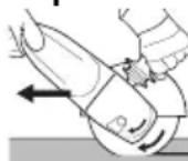
A6pa3nBti kecy ke3iHne apdaNBIM
kapama-Kapcbi 6afttneH (cypETTI
kapaHbI3) kymblc icTeHi3. Kepi
XaFdaiDa acnan keciKTEH KeHET
cekipin WbIFbyMymKiH. OptaHa,
EHneNetIH MaepnAnFa JapamDbI 6epinicneH Kymbc icTeHi3. KucayTuFa, 6acyFa XHe TEHceNTyre 6oMaNdbI.
Ereykym kara3bimeh axkapnay:
AcnantbI opta KUwneH KbICBn, DaNBHaMaHbIH 6eti KaTbKb36aunTBHda ein yCTiHi 6eT 6oBHwa aNfApTKa XblXkBiTBHbI3.
CbIM KbINaKaTpMeH XyMbic ICTey:
AcnanTbI opTaWa KywneH KbICbHb3.
9. Ta3aJay
KymbicapbicbIHda 3neKtpnIK KypandbIH iHHe MaepnAn 6eIweKtepi XnHaanybl MymkiH. Byn 3neKtpnIK KypandbIH cybITbIybiH HaawapnataDbI. Tok etki3riu weriHdi 3neKtpnIK KypandbIH KopraaTbIH OKwaynaftbIWBH 6y3bIN, TOK COY KayinH TydbIPybl MymkiH.
3neKtpnik KypaIdaFbI Kipdi 6apNbIK aIbIHbIMeH apTKbI XeJIDeTy caHbIaynapbI apKbINbI KyJeni Typde, JxI XeHE MyKmT CopbIn HemeCe KypFaK ayamEn YpIen Ta3apTbHbI3. ByI apeKeTTiH anDbIHDa 3neKtpnIK KypaIdbI KyAT Ke3iHeH axkbipTaBn, KopFaHbI Kc3IqipIK neH XapaMdbI pecnnpaTopbl Knin aIbHbI3. YpIen Ta3apTy Ke3iHdE XeTKiniKiTi aya TApTkbl W KeJIDeTy kAMTamacbI3 etiny Tnic.
TytkbwTb peTeyre apHaIFaH TyIme (10): KaKeT 6oJca, TymMeDeH KipDi copBIn Hemece Kypfak ayameH yPJIen Ta3apTbHbI3 (6acblFah Kynde, Heri3ri TytkbWtBn 6apNbIK 3 KyiHde). Byn epeKeTTIH anDbIHda 3JeKtpJIk KypaIbI Kyat Ke3iHeH axbipTaBn, KopraHbI W K3iNdiPik neH pecnnpaTopdbI KIN aNbHbI3.
10. AkayIbIKTapDbI KOHO
Typ TaKaTaNacbHnDa «WE...» 6enrici 6ap acnantap:
-ApTbIK KYKTeMeDeH KopFaHbIC: 3JKeKtpOHDbIK CnHaJIbIK INDkaTOP (6) XaHbIN, KYKTeMe actbIHdafta aHany Xniriri KATTbl TEmeHdeNi. Ko3FaNTkbiI TEMnepaTypacbl TBIM Kofapbl! Acnantbl cybifaHwa XaHe 3JKeKtpOHDbIK CnHaJIbIK INDkaTOP cHReHwe 6oc Kypic KyiHne XymbIC ICTeTIi3.
-AptbIK KyKTeMeH KOPFaHbIC: 3JKeKtpoHdbIK CnHaJIbIK INHdNKaTOP (6) XaHbIN, KYKTeMe actbIHdafta aHaNy Xniniri A3FAHTA TeMeHdeNdi. Acnapka aptbIK KxKTeMe TycTi. 3JNeKtpoHdbIK CnHaJIbIK INHdNKaTOP cHReHWe KymbICTbl TMeHDeTINREH KxKTeMeMe HkALFactbIPbIHbI3.
-3neKtpoHbIK Kayinci3dk axbipatkbIbI: 3neKtpoHbIK CnHaNDbIK INDnKaTOp (6) XaHbIn, acnan e3diirHeH OWEJI. ToKtBih apTybl TbIM XblIdAm 6OJFaH (MbICanbl, KeHet 6yfaTTaJIFaH Hemece Kepi COKkbl TureH) KaFdaNda, acnan eWedeI. Acnantbl 6aTbIpMa aybictbipIn-Kockbl (9) apKbIbI bIeWiPiHi. CoaH KeinH KaTaNKOcbIn, XyMbICTbl EeTTerIeJ KeAIfactbipHbI3. KeinHr 6yfaTTaNyFA Kon1 BepMeH3. 4.2 60nlimH kapaHbI3.
- Kaɪta icke kocbɪnyaH KOPfA hIC: 3neKtpoHdɒblc cnHrʌnɒblk nHdɪnkatop (6) XbɪNbIbIbIbKTAN, acnan xymblc ictemeNi. Kaɪta icke kocbɪnyaH KOpfA hC icke Kocbɪnɒbl. Acnantbɪn Kocyɒbl KyyiHnde keiŋlɪk awa po3etkaFa caɪbɪHfaH Hemece 3neKtp KyaTbɪmeh Jæbɪktay y3ɪn'reHHeH Keiɪn KaɪnbɪHa KeɪreH Jαfdaɪda, acnan icke kocbɪnmaɪɒbl. AcnantbI eWipin Kaɪta Kocbɪnɒbl3.
- Acnan KocbIraH Ke3de MaKcMaJbI aHaNy Xnirine Dein H eTe Xblam yedni, FHN icKe KOCY TOBbH ABTomaTTb TpyDe IeKTERi (6ipKaIbINTb Ice Kocy) KbIMet eTnei. 3NeKTPOHbIK 6NOKta akaybIK opbH anDbI, 3NeKTPOHbIK 6NOK fynHKunlaapbHa KaTbICTb Kayinci3ik TexHnKacbl BoBHnHa 6acka Hyckaynap KepceTinMei. AcnanTb Ipeey XeHdTeH3 (12.-6enimdi kapaHbI3).
W 22-180 MVT, W 22-230 MVT, W 24-180 MVT, W 24-230 MVT, W 26-180 MVT, W 26-230 MVT:
-Kocny npouectepi KepHeydiH Kbicka Mep3imDi TEmeHdeYIH Tydbipadbl. KaFbIMcbI3 KeJI napameTpIepinde backa KypblfBilnap icTeH 1bIfbyMymKIN.ToIbIKKeJI KapcbIbIFbl0,2OM IwMaCbIHah KEM 6OJFaHa, aKayIbIKTapdbIH bIKTmAmIdbIbIFbl TeMeH 6OJaBl.
11. KepeK-ЖаразКтap
Tek KaHa TynHycKa Metabo KepeK-kaPaKaTapbIH KOJaHaHbIHbI3.
Tek KaHa Ocbi NaIdaIaHy BoHbIHwa HyckayIbIKTa KeItipinreH TaIaNTap MeH CnNaTTapFa cai KeIeTIH KepeK-JkapAKTapDbI NaIdaIaNbIHbI3.
Kepek-kaapakapdb6epik 6eKtiH3. Acnan yctaftbiw iwiHne naDanaHbIHaH kaFdaHa acnantb6epik 6eKtiH3. BaKbIay MymkiHirHeH aBipbIcaHbI3, kapaKaT aNyblH3 MymKiH.
4-6eTti KapaHbI3.
OpaaiBIM TEK eHdiipictIK TancbipMaFA Kapambl aImaJIb-CanMaNbl KypaIbI XaHe 6enrIeHReH KopFaHbI W KaNaKTbl naDaHaHBi3.
5-6eTTI kapaHbI3. (CypeTTep Mbican peTInHe 6epijireh).
OHHipicTik TancbipMa:
1=yctihri6etimehaxkapay
2 = abpa3nBtKecy
3 = caHbInay 6ypfbInay
4 = cbIM KblJlJaKaTpMaH XyMbIc iCTey
5 = ereyKYM KaFa3bImeH aXapnay
AnmaIbI-calMaJIbI KypaJdAp:
1.1 = cnbpa axkapnafbiW dHReNek
1.2 = axapnaftbIb6actneK (kepaMknabIK)
2.1 = «MeTann» KeckiW dHreIerI
2.2 = «Kipniшkanay/6eToH» KeckiudHreIeri
2.3 = «Kipniш KaIay/6eTOH» anMaCTbI KeckiW deHreneri
2.4 = eki MaKcaTbI KeckiU DeHreNeKeTep (Kypama aXkapnaFbIu XaHe a6pa3nBti KeckiU DeHreNeKeTep)
3.1 = anMaCTbI 6ypfbInay KopoHkanaPbI
4.1 =DomanaKbInlwaK
4.2 = ta6aKaJbI KbluA
5.1 = nameJIbDi TIpeyiW axapnaFbI W Ta6aKwanap
5.2 = kaxakcbidbipfblnapfa apHaIFaH Tipeyiw axkapnafbwu Ta6aKaWanap
6eJrineHren KopraHbIkw KaIInaK:
A Typi =-KeckiH DeHreNEKKe apHaJFaH KOpFaHbIa KaJNaK
B Typi = axapnayFa apHaIFaH KopFaHbI W KaJIInaK
CTpyi axapnayfaxaHeabpa3nBti kecyre apHaFaNopFaHbIiKaJNaK (KNCbIHdacy)
D Tpyi = axapnafbiw 6actneke apHaIFaH KopFaHbIi KaJNaK
F Tpyi = a6pa3nBti kecyre apHaIFaH aya TaPtaTbIH KOpFaHbIw KaIINaK
KocbImwa kepek-kakapTap:
(www.metabo.com Be6-caNTbIH Da KapaHbI3)
A MetaJIbI Kecyre apHaJIFaH 6aFaHa
B Kbicna raika (14)
C Quick Kbicna raikacbi (1)
Kepek-kaapakTapdbH TOnbIK Ti3iIMH www.metabo.com caHTbIHda Hemece Herizri KaTaNOrTeH KapaHbl3.
12. XoHney

3neKtpnik KypaIJa XeHDey KymbICTapbIH TeKaHa 3neKtpsi MaMaH eTKi3yi Tnic!
KA3AKUAKk
Bv3bnFaH XeJIiK Ka6eIbDi TeK Metabo Kbl3MeT Kepcety opTaJIbIFbIHda catbIn anyfA 6oNaTbIH apHaBbl, TynHcycka Metabo XeJIiK Ka6eJIImeH aybICTbpyFa pyKcat etineDi.
W...B... 6enrici 6ap acnanTapda Kemip KbInwaKTap XnHaFbIH anMaCTbIPFaH Ke3e TeXeriiW KaIbITAPdbI da aJMAcTbipy Kepek.
MetaboФин�ына Кэнчудякжет eTeTiH Metabo3ЛeКТрПИК КралДарБIMENбіреБapьИbI3. Mekeнжайпь www.metabo.com caNTbIHda 6epinreH.
Kocajkb6eJWeKTePdiH Ti3iMepin www.metabo.com caJbIHDa JyKTen aNyfa 60ana.
13. Kopwafrn opTaHbI Kopray
AkapaydaH naJa 60NaTbIH WaHa 3nHdbI 3aTTeKTepe 60Nybl MymKiH, COHDbIKTaH OHbl TnicHwe KeDere XapatyKepeK.
NananaHbInFaH acnantapdbI, opaybiTapdbIXhe KepeK-kaPaKaTapdbI KOpwaHaN opTa ywiH Kayinci3 Typde Kedere Kapaty XeHe KaTa eHdey BoBHwA YTTbIK epKeJepdi YCTaHBiB13.

TeKaHa EO enDiepiHne: 3JNeKtpnIK KypaIdbI TyPmbICTbIK KOkbicka TactamaHbI3! 3JNeKtpnIK XHe 3JNeKtpoHdbIK ecki
KpybIIFbnap KHe YTTbIK 3aHFa TypneHdipy
XeHHderi 2012/19/EU eyponanbIK DnpeKTnBaCbHa
Caikec, naDanaHbInFaH 3neKtpNIk Kypannap
6eneK XnHaBbIN, KopwafAn opta ywiH Kayinci
KaHTa eHdeyre xibepinyi Tnic.
14. TexHnKaJIbI K DepeKTeP
3-6eTteri mJImeTTepre TyciHKTeMeNep. TexHnKaJIbIK dAmyFa Kapai e3repyi MymK
Dmax =aJMaJIbI-caJMaJIbIKypaJIbIH MaKc. dJaMeTpI
t_max,1 = raiKa (14) naIaIaNbIJaFah Ke3deKbICy DnIaIa3OHbIHdAfbI aIMaJIbI- canMaIbI KypaIdbIH MaKC. pyKcaT etJrReH KaJIbIHDbIFbl
t_max,2 = Quick kbiicna raikacbl (1) naJaHaHbJFaH Ke3De Kbcy dNaana30HbIHDaFbI aMaNbI-CAImaJIbI KypaIbIH MaKc. pyKcat etinreH KaNbIHDbIFbl
t_max,3 = cNbpa axkapnaFbI DeHreNEk/KeckiW DeHreNEK: aImaIbI-caImaIbI KypaIbIH MaKC. pyKcat etinreH KaIbIHdbIFbl
t_,4 = _i=1^n n_i k_i n_i w_i a_i k_i t a p_i b_i h MaKc. pyKcat etiJreH KaJIbI HdIbI Fbl
M=wnHneJbdiH npek oimacbl I=aXapnafbiW wnnHdeJbdiH y3bHdbIFbl n0 =6oc kypic kyinHderi aHany xniniri (mKc. aHany xniniri)
P1 =HOMHaIbI TyTbIHbINaTbIH KyaT P2 =WbIFbc KyaT
m=kejinik Ka6eJbc3 caJMaFbl
OJIwey MAnepi EN 60745 cTaHapTbHa caI ecentenei.
AиHbIMaJIbI TOK
BepinreH TexnKaJIbI DepeKTepeIe YfapblHbl ayblKyIap 6onybl MymKiH (kapaMdbI cTahdApTTapFa caI).
3MnccnayIbIK KepcetkiuTep
AtanMbIw KepceTkiWTepeNekTpnik KypaIapDbH 3MmCCnrcBih aHbIKTayFa XHe ePtpni 3NeKtpnik KypaIapDbI caIbICTbipyfa MymKiHdk 6epei. PAndaIaNHy XaFdaIbHa Kapa, 3NeKtpnik KypaIapDbH Hemece anMaIbI-caImaIbI KypaIapDbH KyIbHaibI KyKTMeHi KeTepyi Hemece TeMeHdTeYi MymKIn. KymbICTaBi y3iNicTeppDi XHe pa3anapDbI aHbIKTay YsiH TEmeHipek KyKTMeHi KaMTaMcB3 etIH3. CaikeciHwe BeimdeJreH 6arafa cai naDaIaNhybl yuH KopFaHbc WapanapbH, MbCaIbI, yBIMdaCTbipy wapaIapbIH aHbIKTaHbI3.
Kya Ta6ak MetanbI Hemece yctIHri 6eti Ykenb Baca OHa dipindeiTIN daBHaMaIapDb aXapnay KepcTeINrH WbyIn 3MnCCnrcbHbH KepcTeKiUTePiHe anTapblkTaJ KofapbKaIbNb WbybN 3MnCCnrcbH (15D5 WamacbHa DeiH) Tydbpyb MyMKIn. MyHdai daBHaDamaIapDaH TybHdaTbH WbylNb aybp, NKemdi dipin backbiw KineMeWepepi OPhaty CnKtBi apHaBb Iwaapanap apKbIbI 6oJbIpMayfa 6oJaIb. AckbH WbyI 3MnCCnrcbH, COHDA-Ak WbyIn JyKTemecinH Kayinb 6aFanaFaH XaHe KapamDb KyNaK KopFaHbcBtH TaHdaFaH Ke3De eckepy KaKeT.
IpiJiH xaJIbI KepcTeKlWi (yU 6aFbITbIH BEKTopJIk KocbiHdbicbl) - EN 60745 cTaHdapTbHa caI aHbIKTaJaDbI:
ah,SG =ipinidH 3Mnccnayk KepceTkiwi (yctihri 6eTTepdi aXapnay)
ah,DS =iipinIH 3MnCCnIbIK KepcTeKlIiTI (tipeyiawapnaftbIw Ta6aKaameh axkapay)
Kh.SG/DS =Annci3diK (dipin)
YnriA eIeMdi IbIbIc DeHrei:
LpA =Bb6bcKbCbIMbHbIH DeHreI
LWA =db6bc KyuhiH DeHreH
KpA, KwA =ДэлсizДИК

KopFaHbIw KyaNaKkAn TaftbHbI3!

Catbin anywbfia apHaJfah aknapaT:
Caikectik ceptnufkaTbI:
CeykeciK cepTnФkaTbI: Nc TC RU C-DE.BJ08.B.00909, JapamDbIbIK Me3iMi: 26.10.2017 K.-25.10.2022 K., «INbaHOBCKM ΦOHaCEptnФkaaun» KUHK, «INBAHOBO-CEPTNΦKAT» eHIMdepdi cepTnФkaTay oprahbl bepreh; Mekehkabl (3aHdbI xHe HaKTbl Mekehkabl): 153032, Pecen Φepeaunrcbl, INbaHOBCa obn., INbaHOBO K, CtaHKOcTpontJIb Koeeci, Nq1 yu; ten. (4932)77-34-67; qakc (4932)77-34-67; E-mail: ivfs@mail.ru; AkkpeDntaun aTtEcTaBl Nc RA.RU.11BJ08,
24.03.16 J. AkpeDnTaun BoBbHwa
ФeДералдьКызMetпнбepiIreH
Ondipuyi eJ: TepmaHnna
Öhdpuyi: "Metabowerke GmbH", Metaboallee 1, D-72622 Nuertingen, Германь
Peceire mtnopTaybI:
ЖШК «MetaбоЕврази»
Pecen, 127273, Møckey
Bepe3oBa aannn Keweci, No 5 a, 7-KypbIbIc, 106-KeHce
Tei:+74959807841
HndipinreH KyHi KypaIbIH TaKtaIwacbHa
KepcetinreH 10 TaH6aJIbK cepnJIbK HemipiHne
wnppnHaFaH.1-cah kblbl bInipei, Mbicabl,
«4» caHbI eHIM 2014 kblbl eHdiipilireHIN 6iJdpedi.
2- XeHe 3-caH eHdiipiIreH Kbldafb ai caHbIH
6iIipedei,Mbicanbl,《05》-MaMbip aBl.
ΘHIMHI, kapaMdbIbIK Mep3iMi 7 KbiIDbI KypaIDbI.
HnIpiIReH KYHHHeN KeiH 5 XbIn CaKtayda TpyFaH KaFdaJa aAnbH ana TeKcePmeCTeH naJaAnaHy YcbHbIMaDbI (EHnipinRe H KyHH XanCbIpMaHaKapaHb3).
Пайдалиуьоюнча hyckаманьи Нукypасы
1. Šañkeштигу Туypалу DeКларача
Typy JkaHa cepnIbIK HOMepn apKblny
6eIINHeHReh 6yn KblMaNoOuy MaunHa
TeMeHKyIePrE XoON 6epepn H6n3 e3y6v3dYH JeKe
XoONKePcHInrN6n3 MeHen XapBIAJn6bI3: *1),
DnpeKTbAHbIH 6apDbIK XoBoOnOpyHa *2) JkaHa
HopMaIapbHa *3).TexHnKaJIbIK DoKymEHTTepre *4)
-3-6ETTeh Kaparbla.
Kooncy3nykTy caKTOO MaKcaTbIHda kapaKaTa Ka Tyypa KeIyyu aTaBbH
YbIrapBInraH KoproOuy YexOndy KOnDoHyHy3! Typa 3Mec KoproOuy yexon waimMaHdbi 6aWKapyydAn YbIRbin KeTYYCyHe KaHa ap KaHdaJ XapaKaTTapra aNbn KENYYCy MymkyH.11. Akceccyapnap 6eMyn da kapaHbI3!
2-6et, F cyeTyH kapaHbI3.
- CbIbIpMaHbI (16) ahyh3. Koprooy kantamaHbI (13) KepctyIreH a6aJda opHOTyHy3.
-KoproooykankakTbIka6bik aImarbl KoIdoHyyuHy Kapan TypryaI Kblbn 6bpyHy3.
-CbIbIPMaHbI Xa6bIbIb3. - Kepek 6oIroH yUpya, (cblbIpMa aUblIn TyprHa) BnHTtn 6eKnTyy apKbInyy (17) CblbIpMaHbIH KbInhItyy KvUH Ke6eInTyHy3.
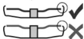
Koprooy kanoTTOH KEMHHe 3,4 MM YbIbIN TyprAn Ns WaaMaHaDapbIH rHa KOJDoHyy KepeK.
6.3 Herns 6ypynMa Tytka
Heru3rTuTka TaBilraH abaIda rHa NHTee (11)KepeK.
2-6et, C cypetyh kapaHb3.
- BacbIyTbI (10) 6acbHb3.
- 3Mn HErn3rN TyTKaHbI (11) 3Kn TapaKka TeH 90^ 6byyn, 6ekntce 6oJOT.
-BekeM OToypraHbIbH IN TeKUeepHnH3: HErn3rN TyTKa (11) 6ekntnInn, 6ypyn6aun KepeK.
6.4 ΘηεκTp TapMarbiHa TyTaawTbipyy
TapMaKtBik WTeNceIb po3EtKaIapb IHePcunJaBik 3pIMe CaKTabiHTap JIINHJbIK KOpROOy aBTOMaTTap MeHeH KoprOlyu KepeK.
Tnntyy ta6aIbHda "WE..." Den Xa3bIraH MaunHaJap:
(Kypr3yyTOKTy aBtOMaTTbIK Tpyde YeKTeRnH KAMTBJINrAe (KaJaDAn Kypry3yy FyHKUraCbI).
TapMaKTBiK WTeNceJIb PO3eTKaIapbl INHepuJIbIK 3pIMe CaKTarblTAP JKe IINHuaJIbIK KOPROOuy aBTOMaTTap MeHeH KOpROnyUy KepeK.
7.Жылmaлооу диСКТи OPHOTуy
Kaipa Ka6dyu NHTepHHnH aNbIHda: Ky6aTTOO uHpyH po3eTKaDaH axbipaTyy 3apbl. CtaHOKty euyyn, uHHdeJIN TOKTOTyy Kepek.
Kooncy3nykTy KaMcbI3DOO MaKcaTbIHda, Kecyyy X3EKTHN KaKKaHbIH KOJIOHYy cyHywTaIaT (AKececcyapnap 6eJMyH 11. kapaHbI3).
7.1 WnnHdJn 6eTtTee
I 55
- UnnHdenn 6eTee (5) 6aKbIyBH 6acbln, UHHdenn H 6eTTeeuy 6ackbIybl 6eETenreHy ce3NJMeHHue (3) KOJ MeHeH aJNaHTbIHb3.
7.2 Kblmaoooy dncktn ophotyy
2-6eT, D cypeTyH kapaHbI3.
W 2..., WE 2...den 6eIInJHeH MaunHaIap:
-Tnpoeuy (2) pnaheuTn uHHdene opHOtHy3. Pnaheu uHHdene aJNaH6aca, Tyypa opHOtUny den 3cenTeNET.
- 6pa3nBdyy TerepekTn D cypetyHne KepcTyrIeHdei, Tnpeev (2) fnaHeuKe opHOtvy3. Xblmaooy Terepek Tnpeev fnaHeuKe Tern3 Otypuy Kepek.
W...A 2... den 6eIrrnHeHre MaunHaIap:
ABTO6aHaHcnpHn Tpueey fnaHeu (4) WnnHdIeIre Kayy 6ekntIeT. BaUKa 6ypTuY KblMaIOOuy MaunHaJapdaH aibIpMaHaBbIN, KOUyma Tpueey fnaHeu Taan KbInbH6aNT.
ABTo6aHaHcnpHn Tnpeeuy φIaHeuHH (4), a6pa3NbDyy TerepeKTH JkaHa (1) Quick Tnpeeuy raikacbIHbH (14) Xe Tnpeeuy raikahbH
6eT Ta3a 6onyu kepek. Kepek yypda anapdbi Ta3anoo 3apbln.
- 6pa3nBdyy Terepektn aTo6banaHcnpnH Tnpeey (4) pnaHeunhe opHoTyHy3. A6pa3nBdyy Terepek aTo6banaHcnpdn H Tnpeey pnaHeunHe Tern3 Otpuy Kepek.
7.3 Quick KbInyBITMa raKacbH 6eKnTyy/ 6oWoTyy (KOMnJIeKTAuNcBHa JapaWa)

Quick KbInyBITMa raKacBn (1) 6ekntyy:
3rep Kblnyy aImarbHdaBn Ws waimaHbI 8 MM DeH KaJbH 6oJco, Quick KblnybITMa raKacBH KOJDOHyra 6oJbOHT! AnDaH COH KblNyBTMa raKaHbI (14) 3KN Ke3eHKeA uKbU MeHen (15) 6eKNTyy Kepek
Bnp raha MaHdEmcN3 Quick KblInybitMa raKacbIH KOJIIOHyHy3:Ke6e MeHeH cbIpTkbl WakeKueHn HOrIg rHa KepyHyWy Kepek (2-6., cyp. kapaHbI3).
- ⅢnHdEiDn 6eTeTTeHy3 (7.1 6eIyMyN kapaHbI3).
- Quick kblnhytma raikacbiH (1) winnHdenre (3) opHOryHy3. CypETTy kappaHb3, 2-6eTTe.
-Quick Kblnhybta raikacbiH caat Xe6ecn 60oHua KOJI MeHeH 6ekntuHn3. - Kblimanoooy terepeKTH Kyu MeHen caaT xe6ecn 60IOHua aIJaNTyy apkblny Quick kbInyItMa raikacbIH bekTNH3.
W...B... den 6enrnneneH MaunHaanapda akbpkbl 180^ kuyTyy TOCKOONdyk MeHeN KOUToNywy KepeK.
Quick KblnhyTma raKacbH (1) 6oWoTyy:
- ⅢnHdEiDn 6eTeTTeHy3 (7.1 6eIyMnKapaHbI3).
- Quick kblnvyItMa raKahbI (1) caat Jke6ecnHe Kapshb 6ypan yeuHn3.
7.4 KbInyblMa raKaHbI 6ekntyy/6oWoTyy (KOMnneKeTauuCbHa JapaWa)
KbInybitMa raJkaHbI (14) 6eKNTyy:
KbIyBtMa raiKaHbIH 26EtN 6bpN-6npHeH aIbIpMaJHaT. KoHTpraKaHbI 7nnHdJIre TeMeHKyDeN Kblbn 6ypaHbI3:
2-6eT, E cypetyH kappaHb13.
A) Kya Ka BImanooy TerepeKTe p uYH: KbIyItMa rKaHbH XomTy (14) eIe kapan TypraHDbIKTaH, Kya Ka BImaNooy TerepeKTo 6ekem opHotyyra 6oJOT.
B) KaIbIH XbINMaIOOuy TerepeKTeP yUH: KblnYbITMa raiKaHBiXOMyTu (14) TeMeH kapan TyprAHHbIKTaH, KblNcBTMa raiKaHbI WnnHdJIeTge6ekem opHOtyyra 6oJOT.
- ⅢnHdEJn6eTToHy3. KbInyItMa raKahbl (14) caat Jke6ecn 6oHua (15) aukbi MeHeH 3kn Ke3eHekKe 6eKnTuHn3.
W...B... den 6enrnenreH MaunHaapda akbpkbl 180^ kuyTyy TOckOoNdyk MeHeN KoTuIywy KepeK.
KbinyMa raKaHb60wOtuHy3:
-ⅢnHdEJn6eTToHy3(7.16JyMyN KapaHbI3).KbInyblMa raKaHbI (14) caaTxeBecnHe KapWbI
KbIPfbl34Aky
(15) aukbIy MeHen 6ypan 3KN Ke3eHKeTHe YeuHHN3.
8. KɔŋdoHyy
8.1 Kyurzy3yy/Thuypyy

Maunha by ap daibim 3kn KOJOn Kapmoo Kepek.

Aderenhe 1aMamdbkyry3yn, aHdah COH daepanma MaTepeNaIra anbIn KeJIyyKepeK.

KokcytaH Jypr3yn anyyydah caKaTHyy yUH: BnIka po3eTKaJa cyppyyn KETKeHDe Jke
3NeKtp Ky6aTbHda 6y3yIyy opyn aIraHda MaunHaHbI eUpyn KOoy KepeK.

Y3ak y6aBkItka KyIgY3yIgHne, MaunHa kondoh 6oWotyIgHda da nItebepet.
OwoHnyKaTah, MaunHaHbI ap daBIM 3KN KOJ MeHeH TyTKacbIHaH KapMaI, TpyKTyU abaIra KeTKnipu, aHdAn COH KymuSha Ka KehyI bypyy Kepek.

HaH Je cypyHdy WaImaHra copyynn KnpuHHe JoJ 6ep6eHn3.MaunHaHbI
eUpyrEHNKINNH KbIMMbIaTkbIy TOKTOHOraHa UHypdy Cyypuw Kepek.
2-6eT, A cypeTyH kappaHbI3.
MometaJyy Kyry3yy:
Kny3yy:BeTTeIyTu (8) Xe6eHH 6aRbITbIHda XblDbipBn, KOtOpryu 6acKbUbH (9) 6acblb3.
Upyy:Kotopy (9) 6acbIHyH KoE 6epnHn3.
TbIHbIMcbI3 NHTeYY (ka6dbIbIbIbHaXapawa):
Kyu3yy:BeetTeryy (8) Xe6eHH 6aBtBnDa KblDbipBIn, KOToPry 6acBtuH (9) 6acBn, KapMan TpyHy3. 3Mm MaunHa Kyry3yNdy. 3Mn KOTopy 6acBtuH 6eTTee yuyn (8) 6eTTeryy DaBti 6np J0ny Xe6e 6oHua (9) XblDbipBbI3 (TbIHbIMCbI3 NWTETYY peKIMn)
Oupyy:Kotopyu 6acbIyBH (9) 6acbln, Kaipa KoE 6epHn3.
W...B den 6eJrInJeHren MaunHaIap:
Kbicka MoeHETKe Knyr3yy (ABTOKTOTyy cyHKnrcbl MeHeH):
2-6eT, B cypeTyH kappaHbI3.
Knyry3yy: KOTopy6aCKbUbH (9) aIbira XblDbIpBIn, KOtopyTu eIe kapa (9) 6acblb3.
Oурyy:KoTopryu (9)6aKbUbIn KoE bepnHn3.
8.2 Nw HycKaMaJapbI
Xbimnmaoo:
CTaHOKTy opTo Kyy MeHen 6acbIn, daarpaJIma MaTePnAnDbIn YcTsyKv 6eNyry eTe bCbIn KeTneuYyH anDbira, apTKa XblnDblpBlh13.
OdypakaJxblmJIoO:KakbIHaTbIJaanyyYyH 30^ -40?C6ypMeHenNHTeKepek.
KbIMmaooy Terepek MeHeH keCyy:
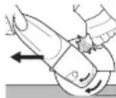
KbImanooy Terepek MeHeH Kecn
KaTkaHa ap DaIbIM NcCKTHN
aIaNbIbIbHa KapWbI (CypETy
KapaHbI3) IwTee KepeK, BoJbOco,
MaINHaHbIH KecnReH KepDeH
Ke3eMeJcY3 Tuyn KeTyy KOpKyHyy JkapanaT.
IwTeJIIN XaTKaH MaTePnaJra bIaNbIKTanraH,
optOo Kyy MeHen NwTee KepeK. OTe KblwaIyyra,
aUbIKya KUY KeNTnpyyre KaHa MaUNHaHbI
yauKOoro KOJ 6ep6ehn3.
Bapa6aHdyy, yoiJraH haxdaKtyy cyprycy MeHen XblImaIooOy cTaHOKTOP:
CTaHOKTy opTo kyu MeHen 6acbIn, daaypdaIma MaTePnAnDbIH YCTYHKV 6eNvY 8Te bCbIn KETneWn YyH anDbira, apTKa XblDblpbHb3.
3bIMdyy ueTkanaP MeHeH uHTee:
MaunhaHbOpToO Kyu MeHeh 6acbHb3.
9. Ta3aJoo
IwTeTIN KaTkHaMaunHaHbIn NcHHe KOUToOy YAH OTpyn KAlbIbIMymKvH. ByJ 3NeKTp WaimaHbIM My3DaTyHy HaayapNaTaT. Tok ETKepyyyu YAH 3NeKTp WaimaHbIHbIKoproOuy H30JIaIcBbH 6y3yn, 3NeKTp COKkyCHy Anyy KOPKyHyH JapaTbIbIMymKvH.
Bnpu kTaN 6aKbI apalnbHda aIdbIHkbI KaHa apTKbl a6a aINaHTyyu Ke3eHKeTp apkblnyy
YAHbl Ta3anAn Je KypraK aba MeHeh YInETyn
Typyy KepeK. Koprooy Ke3 aIHeKTePdN Knnn
XaHa YauHdAn KoproOuy Tyupa KeJreH 6eTKantbl
Kninn IaMnDbl TOK 6yIarbln 6epyyUyeKNTtEH
axbipatbHb3.YInETyy UypyHda XeTNIUTYY
copdyppyUa6 KaMcbI3daJIbIbIbI KepeK.
TyTkahbI (10) Tyypanooy 6ackbIy: 3apbln 60lonco, 6ackbIyTbIh KInpH Ta3aJaNbI3 Ke Kypran a6a MeHen yIeTVHy3 (6acblrA h abalbHa, Heru3rN TyTkahbIH 3 abaJIbHaTeH). An yuyH 3neKtp WaImaHbIH 3JeKTp 6yIarbIH aXbIpTaBn, KoproOuy Ke3 aIHeK XaHa peCnnpaTop KInyy 3apbln.
10. MyuIyTuKTepy Ondoo
TunTyu Ta6aBbHda "WE..." den Ka3bIraH MaunHaJap:
Ausbikya JyKToH KOPRO: 3JKeTPOHdyK cnHn HndNKaTopy (6) Kyuyn, Kyu KeIReHde aHaNyy XbiUtbIgI KaIMKNDEn a3aNaT. KbIMbIJaTkbIyTaIbI aXbIKyA TemnepaTypa! IaImaH My3daBlya JkaHa 3JKeTPOHdyK cnHn HndNKaTopy eKyu, aHbI Kpy KypuWTe NHTeHHn3.
-AuBikya KKTEN KOPRO: 3JKeTPOHdyK CnHaI INDkATopy (6) KInyN, KCh KeINReHde aNaHyy KbiUtbIbI KNUHHE a3aaiat. 3JKeTp WaMHaBHa aBikya KCh KeINReH. 3JKeTPOHdyK CnHaI INDkATopy eKyuTe, TEmH KCh MeHe H NtE BepHH3.
-3NeKtpoHdyk abapnIbIK eUpyy: 3NeKtpoHdyk cInHan nHdNkaTopy (6) Kynyn, MaunHa e3yHoH-e3y OyN Kanat. 3rep yypdaI bcyblIaMdbIgI eTe XorOpny BoIco (MICAJIbI, KYTYCY3eH TOKTON JKe T3n KeTKeHDe)
MaunHa euypyIeT. Ouypyy 6ackbIbH 6acbln, Ka6dbkTbI euypyy (9).MbIHdAn KINH aHbI Kaipa Kyry3yn, KaIMKn peXIMde NwTei 6epu KepeK. KnHHKeIe 6nOKo Twyyp6eere apakETteHrIne. ByI 6enymdy kapaHbI3:4.2.
-KaIraan Kypr3yydH KOPRO: 3NeKTPoHdyK CnHAn HnDnKaTOpY (6) BYLbYlDHT KaHa 3NeKtp WaimaHbI NwTe6eB KaNat. KaIraan Kyry3yyHy 6eETTEeuy TY3Mek NwTeN KeTeT. MaunHa Kyry3yLrEHeJe Ky6aTbI eUpyrReHDe H KInn H Kaipa bepuIreHde UHypdyh BNJkAcbl CaibIbI Typca, MaunHa Kxpr3yy6eHt. MaunHaBbIeUpyn, Kaipa KYIry3yHy3.
- Kyriy3reHne 3neKtp waimaHbI Xoropky aHaHyy KbiUThbIrBaHa eTe Te3 XeTeT, 6.a. JYrpy3yy TOrHyH ABtOMaTTbIK YeKTErHu (KaJdaH Knyr3yy fYHKuJaCbl) mUTe6eBn KaNat. 3NeKTPoHdyk 6JIOKTO KaTa 6ap; 3NeKTPoHdyk 6JIOKTHfYHKUJaPbIH TmNHTYY TexHnKaJIbIK KOONCy3dyK BOHOHa 6aSha Ka KepcETMeJeP JOK. 3NeKTP waimaHbI DaopoO OHDOOR OTKepyHy3 (12.6eJyMn KapaHbI3).
W 22-180 MVT, W 22-230 MVT, W 24-180 MVT, W 24-230 MVT, W 26-180 MVT, W 26-230 MVT:
- KyuIy3yy npoueccTeepHne YbHaNyy KbICKa MeeHOTKe Tswyn KaanT. TapMaKTbIH napameTppepn bHraicb3 60nco, 6aoka acnanTap 6y3yyn KaNbIbMbMyMKvH. TapMaKTbIH TONYK TOckOONdyry 0,2 Omro XeTnece, 6y3yIyy d3apnK opyn an6aayt.
11. Akceccyapnap
Metabo nmpMacbHaH yBikKaH TynHycka TaTnKTeTnKTePdN rHa KOndoHy cyHyTaJat.
Uyyn 6apakyaKeJtnpunreH TaanTapra KaHa MyHe3dEmeIepre TnIMuTYY akceccyapnapbl rana KOnDoHryna.
AkeccyapnapdbI 6ekem opHoTyHy3. 3JekTp
waMaHbIH KapMarbUHTa NwTeTIN KaTKaHda:
3JekTp waMaHbIH 6ekem opHoTyHy3. BaWKapyyHy
Xorotyy kapaKaT anyyra ceBen 6onyu MymKyH.
4-6eTTn kaparblja.
Kymuyu 3JemeHTke Tyypa KeIyyu KoIOnyuy 6eIyK TY JkaHa KepCETYrReH KoproOuy yExoNdy KOnDoHyHy3 5-6eTTn Kaparblna. (CypETep MncaJI 60No aNaT).
Iw TanwbipMacbi:
1 = YCTVHKY 6eTN MeHeH KblImaNoO
2 = Белучу Гунмдр.
3 = TeuNKTePdN KeCyy
4 = 3bIM ΦeTKaIapbl
5 = Haxdkaara3bHbHxblImaIOOCy
KoJonyyy6JnykTep:
1.1 = Kapá JébíMaJIoOouy dIuCK
1.2 =Жылmaлоочуndиш(kepaMknalbIK)
2.1 = KecyyuyДиСК "MeTaNП"
2.2 = KecyyuДиСК "KnpnU/BeToH
2.3 = Kecyyu anma3 nckn "Knpnn/BeToH"
2.4 = ΘKN MUNIeTTn atKapyyuy dNcK (apanaW KblMaIOOuy KaHa KeCyyyu KbIMaIOOuy dNcK)
3.1 = Anma3 6byprynooocy
4.1 = Terepek ΜεΤα
4.2 = έιπις γυγή Μετκα
5.1 = nlaactnHaIbIK XblImaIoooy Ta6aKaHa
5.2 = Kbimmaooy JnCTTep yuy H Kblmnaoooy Ta6aKa
Kazbilaran Koprooy yexoI:
A Tn6n =Bényyky Koprnooy 6nyk
B Tn6b = kblImaNoo yUyH KoprOooY 6eNyK
C Tn6n = XbIImaJoo XaHa (apana) 6eJyyy JXbIImaJIOO YyH KoprooY 6eJyK
D Tn6u = nIiNtTu KblImaNoo yUyH KoproOuy 6eNyK
F Tn6n = copyn anyyuy 3neKtp toryH euypyyy Kopr00uy 6eynk
Башka akceccyapnap: (www.metabo.com kapaHbI3)
A MeTaN Kecyy yuyH Tnpoeu
B KbinybItma raika (14)
C Quick Tipeeyraika (1)
AkeccyapnapdbIn Tonyk accoptmehnH www.metabo.com caTbHaH JKe 6aikbl KaTaNOrDnKapaHbI3.
12. PeMoHT
3JIeKTPHCTpyMeHTTpeMOHTTOO aTaIaUbIraH TeIeO yCTaKaHaIapbIHda raha Kypry3ynyuKepek!
By3yIraH TapMaK Ka6eHH TynHycka Metabo Ka6eHN MeHeH rHa aImaWtBipyy Kepek. AhbI Metabo TeJnnee 6op6OpyHaH caTbIn anyyra 6oNt.
W...B... den 6enrnenreH MaunHaapda
IeTKanap TOnTOMy H anMaWTbIPbIN XaTKaHDa,
TOPMO3 KaNTaTManapbIn Da anMaWTbIPyy KepeK.
Metabo qnpMaCbIHbIH 3JKeTp Jka6DbIKTapbIH peMOHTTOO yUH Metabo eKyIuYnyrHe KaipblbIbI3. IapeKTePn www.metabo.com caHTbIHan TabacbI3nap.
KamdbikTapdbIH TN3MecnH www.metabo.com caHTbHaH KyKTen anacbi3ap.
13. AúnaHa-уeɪpəHy Koproo
Paina 60IroH XbJIMMaJIOO yaHbIHda 3bIH 3aTTap KaMTbIbIbIbMyMKyH 60IroHdyKTah, aHbI TaanTaraDai yTuIN3aCuaJNO KepeK.
3KoIornIbIK Kaipa naJaIaHy KaHa NtTeH YbIKaH Ka6DbIKTapbl, TaHraKTapbl KaHa akceccyapnapbl Kaipa NtTeTyy 6OIOHha yJyTTYK 3pexeJIepn caKaTaBla.
EB eKeIepy yUH rHa: 3u KaaH 3JekTp KypaIapbIn YIDey TaWtAHbI KyTcyHa TaWtAbbIa! KOnDoHyIraH 3JekTpOHNyK XaHa 3JekTp KypaIapbIn BOIOHua 2012/19/EC Ebpona 3peKeIepn 6oHua KaHa yLyTTyK MbI3aMdapra bJaBik, KOJDOHyIraH 3JekTp KypaIapbIn 3yHNe YoYrTyn, aIIaHa-yeIpeRe 3bIaN KeJItnp6BeHEn KeJIbIn bIpRbTIbI W KepeK.
14. TexHnkaJIbIK wapTTapbl
TeTaNapdbIn CypETeJyWHy 3-6eTTeH Kaparblia.
TexNkaBik nporpeccke baNaHbIwTyy
e3repyyIepdy anDbH ana Kaparblia.
Dmax =nWuMaMhBHyH ypyKcat 6epnIreH mAKcMmAnDyy DnaMeTpN
t_max,1 = n KbInyblTMa raKacbl KOJIOHyIraHda KblNbITMaHbH YeRnHdern Nw WaMHaBbHbH ypykcat 6epNJreh MaKcImaJIyy KaBbHbIbI (14)
t_max,2 = Quick KBINyBITMa raNkacbl KOJIOHUYIraHda KbINyBITMaHbIH YerHHdern Ns WaaMHaBbHbIH ypyKcAT 6epnIReH MaKcImaIdyy KaJIbIHdbIRbI (1)
t_,3 = cypyyy Terepek/kecyyy Terepek: nshwaimaHbIHbIN ypyKcat 6epnIreH
MaKcImaNdyy KaJIbIHdbIbl
t_,4 = aK a K a p b i H b i HK a J b i H d b i F b i
M=Kvrgptme ca
=KbImMaNoOuyIINHDeIyIePkTynKnCaNbi
n0 =Kpy KpyuTery aHnaHyy bINaAMdbIRbl (MaKcImaNdy aHnaHyy KbiUbIRbl)
P1 =HomHaIyy KepeKeTeyyy Ky6aT
P2 =Ubyyyky6aT
m=TapmaKa6eIncn3 caImarbl
OJIyHmAAHcN EN 60745 cTaHapTka bIaNbIK aHbIKTaJaT.
II KnaaccTaBjXa6bIK
\~ Θ3repeMe TOK
BepnJreHep Knpn3yyIepyH 3ce6n MeHeh BepnJre (yypdaBcTahdapTTapra binaik).
KaIaIKTap
75 Byn Maahnep 3neKtp HNCTpyMeHTTN KaandbIKTapbIH 6aanaT XaHa ap KaHdA 3neKtp HNCTpyMeHTTepDn CanblbipBn 6epet. Iw peXMMdePHe XapaSha, 3neKtp INHCTpyMeHTTN Xe NaTPOHNy Habapbl, yUypDarbl Mmndetyu NUnHe HxorOpY Ke TEmH 6OlyWy MyMKvH. MnDeTTyy NtTH NtBhlryynapbl XaHa TemeH fa3acblb 6aaoo yUH KapaBlna. BepJireh 6aanapra bIaNbIK KOJDOHyUy UyH TNIWHTYY KooNCy3dyk YapaanapblH 6eJIrInerInne, MICAbl, yIOwTypyy YapaanapblH.
AaHTbI yOH 6eTTepn, Jyka NInCTTepn JKe 6bp a3 dnpunDen TyprAh Hecpepepn XbIMAlaraHda YHdyN KepCEtyIReHdEh DaIbI KeN 4bIbIbHa (15 Da Ra YeHH) c6en 6onyuMymkyH. MbiHdAn Hecpelep YHdyH aMbIKya 4bIyyCyHAn TneWeJyy YapaIap MeHen KoprOlycy Kepek. McaJIbI, YoH nnU3K DeMnΦnpiHe TpyraH KInEmuepep. OoOHdoJ3Je bI3bI-yy TaacnPnIHN KopKyHyUH 6aaNooo JaHa yRyyHyBilaNaBkTyU KOPROOHy TaHDOOO YHdyH KOrOpyJaBbI KapaJIbIbIKepek.
IinpHJDeeHyhKaJIbI eJHcMy (yU 6aBbITbIH BeKTopdyK cyMMacbI) EN 60745 bJaahbIK aHbIKTaJIraH:
ah,SG =INpINIDeOHyH 3MNCCNnBbIK KepCOTKvY (YCTYHKKaTMapDbI Kblmnao0)
ah,DS =4aHkaJyyHyh 3MnccnJbIK KepcETkyy (Ta6ak TpyHdery XblmanoooTerepek MeHen Xblmanooo)
Kh,SG/DS =KaTaIbIK KOaΦΦnueHTN (DnPnDae)
bl3bIyyHvN DeHr3aJn:
LpA =akyctNkajbIK 6acbIM
LWA =akcyTnKaIbIK Ky6aTTyJyK
WaiKeHTNK TaTbIKTaMaCbI:
UaKeTnK TAcTbIKTaMaCbI: Nc TC RU C-DE.BJ08.B.00909, XapakTyy MoeHToY 26.10.2017-#. 6a#tan 25.10.2022-#. YeinH, «UBAHOBO-CEPTNΦHKAT» OOO «UBaHOBckn IOnd CeTnФkaCun» eHymdy TAcTbIKTOO orpaHbI TaPabHaHbepuInre; Dapern(lop. JkaHa paKT 6oHua): 153032, PocSna ΦepeauncaB, UbaHO B6oHua): 153032, PocSna ΦepeauncaB, UbaHO B6oHua): 153032, PocSna ΦepeauncaB, UbaHO B6oHua): 153032, PocSna ΦepeauncaB, UbaHO B6oHua): 153O32, PocSna ΦepeauncaB, UbaHO B6oHua): 153032, PocSna ΦepeauncaB, UbaHO B6oHua): 153032, PocSna ΦepeauncaB, UbaHO B6oHua): 153032, PocSna ΦEpeauncaB, UbaHO B6oHua): 153032, PocSna ΦepeauncaB, UbaHO B6oHua): 153032, PocSna ΦepeauncaB, UbaHO B6oHua): 153032, PocSna ΦepeauncaB, UbaHO
HdpyyIeH eke:epmaHna
ΘΗνργμγγ: "Metabowerke GmbH", Metaboallee 1, D-72622 Nuertingen, Γερμαήσι
PoccydaIbIMnOpTTOOy:
OOO "MeTa6o EBa3n"
Poccn,127273,MockBa
Bepesobar anner Kue., 5 a, ctp 7, 106-KeHce Ten.: +7 495 980 78 41
OHypyIReH KyHy WaaMaHaBbIH 3HTaMraCbIHda KepcTeYIReH 10 opyDyy cepnIbIK HOMepHHe IuΦpIeHReH. 1-can XblbH 6nIInpeT, MncaIbI, 4CaHbI 6yIOMdyH 2014-KblbI eHdpyIReHvH 6nIInpeT. 2 KaHa 3-caHapbl eHdpyIReH XblDaIbI aIbI 6nIInpeT, MncaIbI, (05)-MaI
Biyomdyn KOnDoHyy MeeHETy 7 XbIJ.
HnyyIeHnKnn5KbIcKaTanca,anBHa ana TeKwepe6ecTeH uke Knpn3yy CyHyuTaIbauT (daepaIraH KyHyN 3TNKeTkaDaH kapaHbI3).
OpnirhaIhna IInctpyKci3 ekcnnyataii
f) He BnHOpNCToBvIe 3NoWeHI wLiΦyBaJIbHi dNcN BiD eJeKtpoIHCTpymEtIB 6IbWoO p03mipy. LliΦyBaJIbHi dNcN, BnroTOBLeHi dNpeJ EJeKtpoIHCTpymEtIB 6IbWoO rpo3mipy, He po3paXoBAhi Ha BnCOHy qAcTOTy oBeptAHnMaIOra6apHTnHex eJeKtpoIHCTpymEtIB i TOMy MoKByTb 3pyHbATncr.
g)ПдчаснКОпСТУВаHнДИСЧAMNДЛЯДBox 3aBxDn BnKOpNCTOByte BiDNOBiDHN 3axnCHN KOnyX DnBnKoHaHOrO 3actocyBaHn. HeBnKOpNCTaHHra BiNObiHOrO 3axnCHOrO KOxya MoHe Iprn3BecTn Do BiCyTHOCtI Heo6xIDHOrO ekpaHyBaHn, Ta JH HacJIIOk DO TЯнKOrTO TpaBMyBaHn.
4.4 DoaTHOBI Bha3iBn 3 TexHIn6e3neHN npu BiDpi3aHHi a6pa3NBHMn dnchamn:
a) YnKaIte 6JIOkyBaHH BIDpi3Horo Kpyra Ta 3aHaTo BucOKoro npHTncKHO 3ycNJIA. He BHKOHyTe 3aHaTTO rN60Ki po3pi3N.
IpeBaHTaKeHnB BiDiPI3HOro Kpyra npncKOpOe
Horo 3Hoc i 36iJbUye cxNJIbHiCTb DO nepeKocy a6o
6IOKyBaHHa RK HAcJIIdOK - MOKJIINBicTb BiJaChi
abo pyHyBaHHa.
b) YHnKaIte 3NaXoJHHeHH B 30Hi nepei BiDiPi3Hm Kpyrom, 10 O6eptaetbcra, i no3ady HbOr. Ppi 3MiueHHi BiDiPi3Horo Kpyra B 6OboJIbOHaII DeTani B HAnpami BiD c6e eJeKtpoIHCTpyMeHT y BnPaHy BiDaqui MoKe BiDCHOHTI pRMO Ha Bac pa3OM 3 DnCHOM, 10 o6eptaETbcra.
c) Y pa3i 3aKlnHIOBaHH BIDpi3HOro Hpyra a60 nepepNBaHH pO6OTn BmMHITb eIeKtpoiHCTpymEt i DoueKaHTecr, nOnn Kpyr NOBHicTIO 3yNNHTbcr. HikoN He HAmaraiTEcB BtARHyTN BIDpi3Hn Kpyr, 0o 06epTaETbcr, 3 PO3pi3y - MoJInBa BiJa4a. BCTahOBiTB i ycyhble Te npuHny 3aKlnHIOBaHH.
d) He BMHaIte IHCTpMEnT 3HOBy, RaHcO BIn BCE ue 3NaXoNtbcB O6po6JIbOaHIN DeTAli. Ipepe npOobHeHHm po6To NdoeHaTeCn, nOnn IHCTpMEnT DoCgRHe p6ooyi YactOTn 06ptAHn. IHaKSe MoKInBe 3aJaHHN Kpyra, Ioro BVsCKaHbAHN 3 O6po6JIbOaHOi DeTAli a6o INoBa BiDau.i.
e)Пинраite ПИNTa603arOTOBH BeINKOro
po3mipy, 7O6 3HN3nTn pN3nH y BnnaHy
3aIaHHaBn H3HO Kpyra. BeInki 3arOTOBH
MOHyTB npOnHaTnc NID BlaCHOIO BarIO.
3arOTOBky CIIpiNpaTH 3 DBOX CTOpIH: 6ln3bKO
JIiHi BnKOHAnHry po3pi3y Ta y3DObHK II KpOMKn.
f) BydbTe OcO6nB0 O6epeKHi npu BnHOHaHHi 3aRn6hNx po3pi3iB CtiHax Ta iHnx 3oHax, 1o He nporIaIObCra. Pn 3arN6JIeHHI DnCKa NiJ Yac pi3aHH MoJINBNI KOHTaKT 3 ra30-i BOONpOBoDAmN, eJeKTPnuHOIO npOBODKOIO Ta iHsIMN o6'kTaMn, 1o BnKlnKaE BiDaay.
g) He BnKohyIe KpNBoJIHiHn pi3.
IpeBaHTaKeHH BIDpi3HOro Kpyra npNcKOpIOe Ioro 3Hoc i 36iJIbUye CxINbHicTb DO nepeKocy a60 6LoKByBaHHa, a Ka HacLiDOK-MOHNBicTb BiDaayi abo pyHyBaHHa, lo MoKe PnN3BeCTn Do TAnKKOro TpaBMyBaHHa.
4.5 Oco6nBi Bha3iBHN 3TexhIKN 6e3neHn npu wliifybaHHHaKaDaHm nanepom:
a) BnHOpncTOByTe HaJdaHn nnip BiIDNoBIDHO rO3MIPy, DOTpIMyTEc b IHCTpyNciBnpo6bHnHa 0oD Bo6Op y panepy. HAnDaChn nanip, 10 BuCTynae 3a MeKi TApIyactoro UJIiFyBaJIbHOrO Kpyra, MoKe CTaTn PnPHIO TpaBM, 3aCTPraHn, PO3pHBy HAnDaCHOrO nanepy Ta BiDaayi.
4.6 Oco6nBi Bha3iBKn 3 Texhikn 6e3neH npn BHKoHaHHi p06it 3 dpOToHmM nithaMn:
a) Ppimitbdo ybaru, 0o dpotrahi utkntn Btpaayotb wmaotyn dpOTy TaKOH np3BnuahHomy BHKOpncTaHHi. He npHkaadte 3aHaADTO BnCOHe pNTnCKHe 3ycnJIa.
BidniTaOciI SmaToUKN dPoTy MoKyTb IerKo npoxOuNTn Ckpi3b TOHky TKAHNHy OJrpy Ta/a6o npOHKnATn B wKipy.
YKPAIHCbKAuk
b)Пи ВИнористанни 3axnchoro HOKHyxa He Donyuchaite NORO HOHTaHTy 3dpOTraHOU ⅢITHO. Tapiuacti i yauKOBi uiTKn nid dieIO npNTsCHNO 3ucnilia i BiDcHTpOBHX CNI MOKyTb 36ilbSuBaTN CBi DiAmETp.
4.7 DoaTHOBI Bha3iBn 3 TexHn 6e3neHn:

PONEPENHEHH!3aBKnHaJaRaTe 3axnchi OKyIApN.

HaJaTaIte 3axChi HabyuHnKn.

NONEPEDHEHHIPiJvacpo60TH3aBKnTpImaTe eJeKtpoiHcTpymeHToboma pykam.

He BnKOpNCToBvIe 3axNCHN KOxyn IJ
IiOyBaHHnPiD Yac BnKoHaHHn PO6iT 3
BIDpi3aHHn ABpa3HBMn DNCKAMn. Pid Yac
AHnPO6iT 3 BiPi3HNMn DNCKAMn 3 MeTOIO
KN KOpNCTuTEcra 3axNCHM KOxYXOM IJ
AHHaBpa3NBHMn DNCKAMn.
He BnKOpNCToBvTe cerMeHToBaHi aIma3Hi BiDi3Hi KpyrN 3 BiDCTaHHIO MIX CeMeHTaM NOnHa1 10 MM. DOnyckaETbCRA BnKJIIOUHO BiJ'EMHNI Kyt pi3aHHc CerMeHTa.
BnKOpncToByTe 3'eHaHi BiDiPi3Hi KpyrN TiIbKn, AkiO BOH NocnJIeHi.
BnKOpNCToByTe eJnactuHbKn, RKnO BOHn BXoJaTb DO KOMnEHTy a6pa3nBnHex IHCTpyMeHTi BnPo6HnK HanoJIrae Ha ix BnKOpNCtAHHi.
DotpmyTecbpeKomeHdauiBnpo6Hnka IHCTpyMeHTy Ta npnilaJr! 3axuauTe DnCKn BiD NOTpanJHnMaCTnla Ta ydapib!
36epiraTe iHCTpyMeHTaJIbHI HacaIKN Ta NOBOdTEc3 HIMN BiIOBIDHO DO BKa3IBOK Bnpo6Hnka.
He BnKOpNCToBvIe BiDiPi3Hi Kpyr nIyOphOBoro 1iIyBaHnA6o BnJaIeHHN 3ayCeHeu! Tpe6a yHnKaTn 6iHOro TnCKy Ha BiDiPI3Hn Kpyr.
3aROTOBka NOBHHa HadiHNo npJIraTH Do
NOBePxHi Ta 6yTu 3aKpIJIeHa BiD 3iCKOB3yBaHHa,
HAnpIKJa, 3a DonOMoTO 3aTnCKHnx pInCTpoIB.
ДЯ BELINKHX 3aROTOBOK Tpe6a NepeIb6aHTNt
DOCTaTHIO ONOpY.
Pn BHKOpCTaHHi IHCTpyMeHTaBbHx HacaDOK 3 pi3b60BOIO BCTaBHO KIHeCb IINHDeJI He NOBHeH TOpKaTHcNepΦopOBaHOI OCHOBn a6pa3HBoro IHCTpyMeHTy. NpeKoHaTecr, Io p3b6a IHCTpyMeHTaBHOI HacaDN Mae DOCTaTHO DOBXHNy DIA KpINLeHNr DO WNNHDeJI. Pi3b6a IHCTpyMeHTaBHOI HacaDN NOBHNa CnIBNaTaTI 3 pi3b6O IO WNNHDeJI. DaHI UDO DOBKNHr Ta pi3b6u WNNHDeJI DN.Ha CTOp. 3 Ta B po3di1 14. TexHiYi xapaKTepNCtIKN.
PeKOMeHDoBaHO BnKOpNCToBbATn BiIDNOiDHN CtaioHapNn BnTJXHHN PnCTpi. 3aBXdni NiKJIouaTe npncTpi 3axnCHoro BiKJIoueHHN (Pi3B) 3 MaKcImaJIbHmC TpyMOM BnTOky 30 mA. IicIa BiKJIoueHHN KyTOBOi WlifMaunHn PnCTpOcM 3axnCHoro BiKJIoueHHN Tpe6a nepeBipNTn Ta NouchTtN MaunHy. DnB. po3di9. YnueHH.
He BnKOpNCTObYTe NOsKOJKeHi, EKcEHTpNHi Ta Bi6pyuOi IHCTpyMeHTaJIbHI HacaIKN.
YHnKaIe N0sKoJKeHHra3OBHX Ta BOOpOBIaHNx Tpy6, eJIeKTpHuHOI npOBKn Ta HecyHx CTiH (CTaTnKa).
Ipeed npoBeeHnM pO6IT 3 HaJauTyBaHHn, nepeoChaueHHa 60 o6ClyroByBaHHn BHTTb BnIKy 3 po3ETKn.
NoWKoJKeHy a6o noTpickaHy DoaTKOBy pyKoRTKy cIiD 3amInHt. He ekCnJIyAtyTe MaunHy 3 NOWKoJKeHoPyKoRTKOIO.
PoiKoJKeHn a6o notpickaHn 3axnCHn KOxH x C1iD 3amHHTn. He eKcnIyatayTe MaunHy 3 PoiKoJKeHm 3axnCHm KOxHxOM.
He BMnKaIte iHCTpymeHT, kNo Ioro DeTaJI a60 3axiChi npncTpoi BiDcyTHi a6o yuKoJKeHi.
MaunHn 3 nlaBnM nycOM (3 mApKyBaHHaM "WE..." HaTexhui Tabnuci): RaKo npn 3anych MaunHa dyKe WbNDIO pncKOpOeTbcr Do MaKcImaJIbHnx OBeptIB, To Mae MicCe NOMIka B eJeKTPOHOMy 6Looi. He MoKHa po3paxOByBaTH Ha iHsi FyHKuE JeKtPOHOrO 6LOKy, RKi BiNObIaIOb 3a 6e3neKy. HeraHNo 3daTe eJeKTPOIHCTpyMeHT B peMOHT (INB. PO3d1 12.).
3aKpInIIOHe MaJI 3aROTOBKn. BnKOpNCTOByNe, HAnpNKlaI, neUaTa.
JHKUO DNCHN, BCTaHOBJIeHI Ha 0JIaHci,
BNKOpNCTOBYOTBCr DnI DBOX CIJIeN (KOM6iHOBaHi
WIIfYBaJIbHi DNCHN Ta a6pa3NBHi DNCHN DnI
BiDpI3aHH), MOKHs BnKOpNCTOByBaTI TIlbKn TaKi
TINN 3axnCHNX KOJyXIB: TnI A, TnI C.
DNB. po3di1 11..
BHHOPNCTOByTe BiIDNOBIiHn 3axHCHN KOHyX:
BnKOpNCTaHHeBIDNOIBHO3axnCHOrO KOxya MOKe npu3BeCTn DO BTPaTH KOHTPOI TO Ta TAKHO TpaBMyBaHH. PnKlaDn HeHaJIeKHO RnKOpNCTaHH:
-Пдчасвикорпстаннгзхисного кхуха.TNYAДлЯшліфувангТорцemКрура3хиснй кхуxTa 3aROTOBkaMOKHyTB3aBaKaTHОДHe OДHOMy,単прИЗBEDEДо HeDOCTaTHbOro KOHTpoJIIO.
-Пдчасвикорисангязaxис HorO кжуха Tnny BДЯ abpa3nBHorO BiDpi3aHHЯ 3a DOnomorOHO 3'EDHaHnx BiDpi3Hnx KpyrIB BHNKacпдВицeнн риЗн BiD icKOp, lo BiDJItaIbTb, TaЧАСТOK BiD wLiФуВань, a TaKoJ yIamKIB WLIΦyBaIbHOrO Kpyra y pa3i NOro po3IOMy.
-ПдчасВИКОРИСТАнгЯЗХСHOrO KOKHyxa TINIB A,B,CДЯ abpa3nBHoro BiDpi3aHHa60 шлфуванн Topcem Круra 6eToHу a6o ueIHOI KlaDNK BUNHKaE NiDbuIeHn Pn3NK Upe3 NINOBE HABaHTaKeHHa, a TaKoK Upe3 BTPaTy KOHTpOJIIO 3 BiDauJeO YK HacLiIDOK.
-Пд ус ВИКОРиСТаннэ 3axиСHоRo KOxуха TUNiB A,B,C 3 TarIчacToO uTko,TOBинa RAKOI nepeBnUyE DoNyCTmY,ДрOTn MOxTyb 3ITKHyTnC3 3axиСHIM KOxухom i Ze moXe npu3BecTn Do IX 3JAmY.
3aBKn BnKOpNCToByTe 3axnCHn KOxH, 10 niXoNTb Do IHCTpyMeHTaIbHOi HacAn. DnB. po3dIn 11..
3HHHeHHBnNBy nIy:

NONEPENHEHH-NNI,IOYTBOPINBCB HbacnIDOK WlifyBaHH HaKaHMM
naepom,po3nHIOBaHH,UIiΦyBaHH, CBepdHH Ta iHxNPObi, MICTb xIMiHi peOBNH, 0C npuHnroB paK, BpOJKeHi DepeKTn a6o iHwi ykoDkeHH pePpOyKTNBHOI cnCTem. PnKlaDi TaNX ximHnx peOBOH:
- CBNHecb y φap6i 3 BMICTOM CBNHQU
-MinepaIbHn nn 3 6yDInBeIbHOI cErJI, cEmeHTy Ta iHNx peOBN cErJIAHOI KlaKn, a TaKoK
-MNJHK Ta XpOM 3XIMiHNO O6pO6JIeHOI DepeBHNCTynInb pN3nky 3aJeKHTb BiD TORO, Jk qacto BN BnKOHyTe ue BnBd po6it. Uo6 3MeHUnTN BnINB XIMiUHX peOBOHN: PpaIOHTe B nPmIuEHHx 3 DOCTaTHbOBeHTnJaiceto Ta 3 3aTBepdKeHNM OC0buctHM 3axNCHM CnpAJaHeHHM, Jk-OT pecnipatop, PO3pO6JIeHN CneiaJIbHo DIAJ FJIbTpaqii MiPKoCKOnIHNX qactnHOK.
Ie TaKoK CTocyETbcNnly BiD iHnX MaTepiAIB, HAnpNKlaD DeaKNx BnIDIB DepeBa (DepeBnHHn nn dyba a6o 6yka), MetaLy, a36ecTy. IuSi BiDiomi 3axBopIOBaHHra-ue, HAnpNKlaD, anepriHi peakii, 3axBopIOBaHHra dnxAlbHNx WJIAxB. YnKaIte NotpanJIaHHn NnLy BCEpeDInHy TiJa.
Dopmyteb Bka3iBOK CTOCOBHO BaWOro MaTepiany, nepcoHaNy, cfepn Ta Micya BHKOpNCtAHnA, a TAKOH DePKaBHx npaBnI (HapnKlaI, nOLOKeHHn Ipo OXOPohy npaCi, yTnIi3aCiIO Toio).
3a6e3neuTe yIOBIOBaHHaNly B Micci yTBOpEHn, He dOnyckaTe NOro BiKlaJeHHa NaOBepxHax.
Iy Cneuiahnx po6it BnKOpncToBy Te BiIOBIDHe npnila. Lc Do3BOJNTb 3MeHHTN KJIbKiCTb NIIy, 10 HeKoHTpOlbObaHO NOTpanJIOTb y DOBkllna.
BnKOpncToByTe BiIDNoBIiHi 3acO6n yIobJIIOBaHHa nnly.
J3MeHHeHHBnNBy N
- He HanpaBnIte NOTIK NOBITpr, 10 BNXOJNTb 3 IHCTpyMeHTa, Ha Ce6e, IIOJe, JKI 3HAXOJrTbcra NOBJN3y, Ta Ha CkyNJueHHNJIy;
- BHKOPNCTOByTe BNTJHHN npNCptpi Ta/a6o OUYBaH NOBITp;
- DObpe npoBriptpojTe po6Oe Micce Ta 3a6e3neuYte YnCTOTy 3a DonOMoroIO NnIOcoca. NiIMiTahHra Ta BNDyBaHHra 3diMae NnI y NobiTpa.
-3axnchnojOaIqOuHCTHTN3aDOnOMoTO nnloocaa60 npaHn. He moKHa noTo npOdyBaTH, Bn6BaTH a60 uHCTHTUitKOIO.
5.Orna
DUB.CTOp.2.
1Швднозатинckha raIGNa Quick*
2 OnopnH ΦlaHeCb*
3Unnndelb
4 W A... onopHn φlaHeCb aBTo6aHaHcnpa (He3HIMN)
5KhonkaphiKacaiiIHHndela
6 EneKtpoHHn CnHnaJIbHN iHnKaTOp
7PyKoRHa
8 ΦικaTOp (ДЯ 3axncty BiД BnnaIkoBOro BMKahHra/ aKTnBauciб 6e3nepepeBHOrO peKIMy po60Tu) *
9 HaTnckHn nepemHKaY (YBIMK/BIMK)
10 KhoNka (JnpepyJIIOBaHHaOCHOBHOI pyKoRTkn)
11 OchoBHa pyKoTka
12 DoaTKOba pyKoTHa /doaTKOba B6ponorlnHaOua pyKoTHa
13 3axnchnoKohyX
14 3aTnckHa raHka
15 KJIou niДBa OTBOpn*
16 KJIaMHa (ДЯpeRyIIOBaHHa3axHcHOro KoKHyXa 6e3 iHCTpyMeHTy)
17 TBNHT (Для ретуловаHHЯ 3aTnCKHOrO 3yCINJI KIAIMKU)
*3aJIeHHO BiID KOMnJIeKHaTcii / He BXoHt b y KOMnJIeKT IOCTaHaHH
6. BBeDeHnB eKcnLyataciio

Ipeed noaTkom po60n nepeKoHaTeC8, 10 Bka3aHi Ha TexHcHt Tabnuc nplaNy
HAnpyra Ta YacToTa B MepeXi CnIBNaIaHOb 3 DaHIMBaWoI eNeKtpomepexi.

3aBxnnPiKnHouaTe npncTpi 3axnchoro
BIDKIOUeHHa (I3B) 3 MaKcHMaJIbHIMCTpyMOM BHTOKy 30 mA.
BnKOpNCTOByTe NOOBKyBaIbHn Ka6JIb 3 MIHimaIbHm nepetINHom 1,5 MM². NIOOBKByBaIbHi Ka6JIi NOBHHI BiIDNOIBaTn CNOXHBaHI NOTyKHOCTI IHCTpyMeHTy (nopIBH. TexHiHi XapaKTepnCTnKi). PnBnKOpNCTaHHi Ka6JIbHorO 6apabHa Ka6eJIb cIId NOBHICTU p03MOTaTI.
6.1 BcTaHOBLeHHaDoatKBOIpyKoTTH

PnBukohHHi 6yDb-RAKnx pObi 3aBKnMae 6bTu BCTAHOBLeHa DoaTHKOba pyKoTka (12)!
BkpyTiTbdoataKOBy pykoTky do ynpy B liBni, cepeHni a6o npabn (3aJIeKHO bID noTpe6n) pi3b6obn OTbip i 3aTgHiTb BiD pyKn.
6.2 BctaHOBJIeHH3axnCHoro KOnyxa
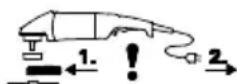
Ipeed noaatkom po60tn: BCTaHOBITb 3axnCHN KOxYX.

3 npuHn 6e3neKn BnKOpncToBynte
BnKIOUHO 3axHCHN KOxYX, npn3HaueHn Iy BIDNOBIDHOI IHCTpMeHTaIbHOI HacaKn!
BnKOpNCaHHeBIDIOBHO3axNCHOroKOxya MoKe npu3BeCTNo BtpaTH KOHTPOITo Ta TAKKORO TpaBMyBaHH. DnB. TaKOH po3dIn 11. PpnaJa!
INB.CTOp.2,MaI.F.
-BiDkPnIte KJIaMky (16).BCTaHOBIb 3axNCHNI KOJx (13) Ha Bka3aHe Micce.
-Поверніть кOKуx 3aKpntOIO CTopoHOIO Do KOpNCTyBaaya.
-3aKnIe KJIaMky.
- 3a Heo6xHocTi 36ilbWitb 3aTnCKHe 3cHJIJI KJIAMKNI, 3aTARHyBwN rBNHT (17) (npn BiDkPnti KJIAMCi).
YKPAIHCbHKAuk

BnKOpNCToByTe IHCTpyMeHTaJIbHi HacaIKN, Iki 3axIChN KOxUx nepeKpNbAc He MeHwe, HkHa 3,4 MM.
6.3 NobopoTHa OCHOBHa pyKoRTHa

IpaqOnTe TlBKn i3 3aqiKcObaHO OCHOBHOpyKoTko1 (11).
ДиВ.стор. 2, мал. C.
- HaTnCiHtB KhoNky (10).
- OCHOHy pyKoTky (11) MoKHa noBepHyTN B Ody 3 DBOx CToPiH Ha 90^ i 3aΦiKCyBaTu.
- IpepeBipTe HaidHicThb Nocaikn: OCHOBHa pyKoTHa (11) NOBHHa 3aΦiKcyBaTnCra Ta He oBeptatncr.
6.4Плкlioуеняdo eJeKtpomepehi
TencbHipo3eTKnKINBHeHHMaOTb6yTN 3axuhehiIhepuiHMMnPnaBKMn3aNo6iXHKamn a6oJIiHIMN3axNCHMnabTomatm.
MaunHn 3 MapkyBaHHaM "WE..." HaTexHiHni Ta6nuyi:
(3i B6ydoBaHm aBtOMaTHHM 06MeJyBaHem NyckOBoro ctpMy (fYHKcIeIO nlaBHoro nycky)).
ITeNceJIbHi po3eTKn HINBLeHHeMaTOb 6yTNI 3axuIeHI IHepuiHIMN PIABAKHMN 3aNo6iKHNKAMN a6o LiHHMn 3axNCHMn aBTOMaTAMN.
7. BctaHOBJIeHHnI shiΦyBaJIbHOrO dNcHa

Ipeed6ydb-ramnpo6oTaMn3
IpeoChaueHnHaBxDn BNTraTe BNkky 3
po3eTKn.MaunHa nobHHa 6yTN BmKHeHa, UNHdJIb NOBHeH 3ynHHTNCr.

Ppno p60ti 3 BiDiPI3HIMN DnCKaMn 3 MeTOO
6e3neH KOpNCTyItec3axnCHM KOxYXOM
ДЯ BiDiPIaHHa 6pa3HbHMn DnCKaMn (DnB. po3di 11. PpIaIaJIa).
7.1ΦiKcaui wnnHdeJia

KhONKy fikcaqii shnHdJe (5) MoXHa HATNCKaTN TiIbKn npH HepyXOMomy
wnnndeni.
- HaTnCHiB KhoNky fikcauii uHHdela (5) Ta nobepHITb uHHdela (3) pykoIO,doKu KhoNka He 3aphiKcyETbcra.
7.2 BctaHOBJIeHHIJIiΦyBaJIbHOrO nIcHa
ДиВ.стор. 2, мал. D.
Maunn3 maphybaHHm W 2..., WE 2...
- BctaHOBIb onOpHn ΦIaHeu (2) Ha IINHdeJIb. ΦIaHEuBCTaHOBJIeHn npaBnJIbHO, RaKIO BiH He OBeptaETbcra Ha IINHdeJI.
BCTaHOBIb ⅢIiΦyBaJIbHn DnCK, Ra NOKa3aHo Ha MaJIIOHNy D,Ha onOpHn ΦJIaHEuB (2). ⅢIiΦyBaJIbHn DnCK NOBHeH pIBHomipHO npINJRAtn Do ΦJIaHua.
Maunn3 maphyBaHHm W...A 2...

OnopnHnΦlaHeCb aBTo6aJaHcnpa (4)MiHOp npKpInIeHn Do uHHdJeA.AnAoIyHo do
iHux KuyTOBnx 7JIΦMaunH TyT Hemae nOTpe6n y 3HIMHomy onOpHOMy fHaHci.
KoHTaKTHi NOBepXHi OOnOpHOro FJIaHcIa ABTo6aHaHCnpa (4), WlIiCyBaIbHOrO DnCKa Ta 3aWNIDKO3aTnCKHOI raiKn Quick (1) a60 3aTNCKHOI raiKn (14) NOBHHI 6yTH NCTHMN. OunchTe 3a Heo6xIdNocti.
- POKlaDiTb ⅢIiΦyBaJbHnДИСК Ha onOpHn ΦlaHeuB abTObαlaHcnpa (4). ⅢIiΦyBaJbHnДИСК NOBInHeH pIBHomipHO npJIraTn Do ΦlaHcz.
7.3 3aTgHeHHBbIckpyBaHHbWbNIO3aTnCKHOIraHKn (3aJIeXHO BIDKOMnJIeKHTaii)

3aTARHeHHaBnKo3aTnCKHOIraKN (1):

IHKIO IHCTpyMeHTaJIbHa HacaKa B Micci 3aTnCKy Mae TOBUnHy 6JIbWe 8 MM,
WBnDKo3aTnCKHy raKy BnKOpNCTOByBaTu He MoXHa! Y cboMy BnnaDky KOpNCTyITeC 3BnuAHOIO 3aTnCKHOIO raKOIO (14) Ta BiNOBiDNHM KJIOnyem NiD DBA OTBOPN (15).

BnKOpncToByTe TlBKn HeyuKoJKeHy WBNko3aTnCKHy raKy: CtpiKa NOBHHA
BkayBaTHa BnIMky 3OBHIuHbOro KJIbUra (INB. MaIOHOK Ha CTOp.2).
-3aφikcyIte wnnHdeIb (nVB. po3di7.1).
- BCTaHOBIb 5BnIko3aTnCKHy raHy (1) Ha 5nnHdJIb (3). DnB. MaI. Ha cSTOP.2.
-3aTnHtB WbNko3aTnckHy raKy pyKaMn 3a rOHHNKOBIO CTpiJKOIO.
-NotyHHM NOBOPOTOM WlifyBaJbHOrO DnCKa 3a RoINHHKOBOIO CTPIIKIO 3aTARHiTb WBNIDKO3aTNCKHy raIHy.
Y MaunHax 3 MapkyBaHHm «W...B...» Ha octaHHix 180^ BiDyBaETbcra 6IbIsh 3HaHn CynpoTnB.
BiDkpyyBaHHaBnKD03aTnCnHoi rAHH (1):
-3aφikcyIte winnHdJIb (DnB. po3diJ 7.1).
-BiKpyTtB WbNdko3aTnckHy raKy (1) npOtI rOHHNKOBOI CTpiKN.
7.4 3aTnHeHHBipHyBaHH3aTnckHoi raHn (3aJIeHHo BiKOMnIeKtaui)
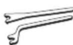
3aTARHeHHaTHcHooIraHKn (14):
3aTnCKHa raKa Mae 2 pi3Hi CTOpOHn. HaKpyTiTb 3aTnCKHy raKy Ha IINHdJIb, JIK NOKa3aHO Ha MaJIIOHKy:
ДиВ.стор. 2, мал. E.
A)ДЯTOHнxшлcfyBaIbHnxДиСИВ:БурТИКЗATNCHNOIraIKN(14)nobepHyTNIDOROpN,IIO3a6e3neUeHaJIHHN3aTnCKTOHKnXDINCHIB.
B)ДЯTOBCTnx wIiΦyBaJIbHnX dNcKIB:
BypTNK 3aTnCKHOI raHKn (14) NOBepHyTNI DOHN3y, 0o 3a6e3neUye HaDiInHe po3TaWbAHNraHKn Ha WnHDeJI.
- 3aφikcyte wHnHdeIb. 3aTgHiIb raHy (14) KIOUcH PiD IBa OTBOpN (15) 3a RoINHHNKOBIO CTPIKIO.
Y MaunHax 3 MapkyBaHHM «W...B...» Ha octaHHix 180^ BiDyBaETbcra 6IbIsh 3HaHn CynpOTNB.
BidkpyuBaHHaTnCHHOraHH:
-3aφikcyIte winnHdJIb (nVB. po3di7.1). BiKpyTiB 3aTnCKHy raHy (14) KliOyem NiD Dba OTBOpN (15) npOTn rOdnHHNKoBOi CTpiKN.
8. EKcnnyatacia
8.1 yBIMKHeHHBIMKHeHH

IhctpymEnT 3aBxN Tpe6a TpMaTH O6oma pyKaMn.

IiBbTe Do 3aTOBKn TiIbKn yBIMKHeHn IHCTpymeHT.

He donyckaite Heymnchoro 3anycky: 3aBKn BmHKaTe iHCTpyMeHT, RkUo BNkaBnTHyTa 3 po3eTKn a6o RaKuo CTaBCr 36iB.4u ci eJeKTpoEhepriii.

Y peKmI 6e3nepepBHOi pOBoTH iHCTpyMeHT npoDBKyE npaQOBaTH, HABiTb RnIO BiH eTbcr 3 pyK. Tomy 3aBxKn MiCHO TpMaJTe pOMeHT DbOMa pyKaMn 3a pyKOHTky, 3aIMiTb Ke IIOJOHeHH I NOBHcTIO CKOHcHTpyNTec MOKHYBaHi pOboTI.

He donyckaTte 3aBnXpeHHa60 BCMOKTyBaHHIHCtpymENTOM NIIy I TnpCNI.
He KlaTb BmKHeHn eKeTpoIHCTpyMeHT Do NOBHOI 3yINHKn DBNrHa.
INB.CTOp.2,MaI.A.
HopoTHoUacnI peKHM po60Tu:
YbIMKHeHHa: nepecyHbTe fiKcaTOp (8) yHaNPmky CTpiKN i HaTnCHiTB HaTnCKHn nepemnKaq (9).
BIMKHeHHa: BiDnyctiTb HaTnckHn nepemnkau (9).
Be3nepepeBHH pexnM po60TN (3aJIeHHO BID KOMnIeKHTaui):
YbIMKHeHHa:pecyHbTephiKcAtop(8) yHaPmky CTpiKN,HaTncHiTBpepMnKau (9)i yTpmyte noTo HaTncHeHm. IHCTpyMeHT yBIMKHeHn. PepeCyHbTephiKcAtop (8) 1e pa3yHa npMaKy CTpiKN, 0o6 3aΦiKcByTu HaTncHNnpepeMnKau (9)(6e3nepepbH a pObota).
BIMKHeHHaTNCiTB nepemkaq (9) i BiDnycTiB Noro.
Maunn3 mapkyBaHHm «W...B»: MomentaJIbHe BBIMKHeHHr (3 yHkuicIO abTomatNuHOI 3yHHN)
ДиВ.стор. 2, мал. B.
YbIMKHeHHa:HaTnCKHnpeMnKaU (9) nepecyHyTN Bnepei nicJaTO HaTnCKaHHaMpeMiciTn HaTnCKHn nepeMnKaU (9) DorOpu.
BnMKHeHHaBnPyCTHTHaTnCKHn (9) nepemka.
8.2 Po60qi Bha3iBHN
山iΦyBaHHa:
PnHTNcKyIte iHCTpymeHT 3 NOMIPHM 3yCNJIaM i nepemiiuyTe Ioro no NOBepxHi Ha3aI IBpepe, 06 nobepxHraOTOBKn He neperpiBaJacr. O6dnpHI pO6Ot: dIy OTpMaHnHa Do6poro pe3yIbTaTy npauOHe 3 KytOM HaxIny 30^ - 40^
Bidi3aHH a6pa3NBHMn dNcAmn:
Ipn BiDpi3aHHi a6pa3nBnMMn DnCKamN 3aBXnn npaouTe B 3yctpiHOMy Haprmi (INB. MaIOHOK). IHaKHe IHCTpyMeHT MoKe HecNoDiBaHO BVsCKoHTN 3 npONJy.
IpaouTe 3 nomipHO IOndaueo, BiIOBIDHO OoObo6IOBaHOro MaTepiAly. He IOnyckaIte nepeKocy, He HaTnCKaIte i He po3roI dyIte IHCTpyMeHT.
UliyBaHH 3 BnKOpNCtAHHm UliyBaJbHoro nanepy:
PnTnckyIte iHCTpymeHT 3 nOmiPnHm 3cynllam i nepemiiuyTe NOro No nobepxHi Ha3a I BnepeD, 06 nobepxHa 3arOTOBKn He neperpiBalaac.
06po6ha npotAHMMn iTkAMN: NOMIPHO npHTNCkyte iHCTpymENT.
9. OvnüeHHa
Ipnpo6oTi MoKJIbBe ChyUeHHaCTOK
Obo6pIIOBaHOro MaTePiAly ycepeNHi
eKeTpoIHcTpMeHTy. Ce noripWye OxolodKeHHa
eKeTpoIHcTpMeHTy.CTpymOpOBiHi cKUneHHa
MOKyTb NoripuHTn 3axHCHy i3OJIauIO
eKeTpoIHcTpMeHTy, IO BHKInKae pN3NK
ypaKeHHa eKeTpruHm CTrpMOM.
Yepe3 HeBENKi PiBHi npomixn yacy peTeIbHO OunuYte NpeaHI i 3adHI BeHTnlauiHni UINHH eKeKtpoiHCTpyMeHTy a6o npodyBaHTe ix cyxHM NOBITpAM. Npeed cIM M BiD'EDHaTIe eKeKtpoiHCTpyMeHT BID dKepeLa KInBLeHNr I HAdiHbTe 3axNCi OKyIrpN i BiNDOBiDNH pecnPapToP. 3BeptaHTe yBary Ha TexHiHo npabNlbHy BVITXkN pyn BVdyBaHHi.
KhoHa (10) peryIIOBaHH pyHOaTHn: 3a Heo6xHocTi BnJaIe Te 3a6pyDHeHHa 3a DonOMoroIO nIIOcoca a6o IJIaXOM BnDuBaHH CyXIM NOBITpAM (KHONKa B HaTNCHTOMy IIOJKeHHi, B 3 IOJKeHHx OCHOBHOI pyKOaTHN). Ipeed cIIM BiD'EdNaTe eJeKTpoIHCTpymENT Bd DkepeLa KInBLeHH i HAdiHbTe 3axnChi OkyIapri i pecnipatop.
10. YcyHeHHa HeCnpaBHOCTeH
MaunHn 3 MapkyBaHHaM "WE..." Ha TexHiHiI Ta6nHi:
- 3axnct BiD nepeBaHTaHexHH: rOpNTb eIeKtpoHHN CnHaNbHN iHdNKATOp (6), Yactota ObeptaHH Nid HabaHTaHexHHM IOMITHO 3MeHwcyTbcra. Temepatypa DnuryHa 3aHaTo BnCOka! 3aJIuTe MaunHy npaQOBaTH Na XOJIOCTOMy XODi, DOKN
YKPAIHCbKAuk
TemnepaTpa He 3Hn3ntbca i eIeKtpoHHN CnHnabHn IHnKaTOP He 3rache.
3axnct BiD nepeBaHTaKeHHa: ropntb eIeKtpoHHN CnHahbHni iHnHaTOp (6), yactota 06epTaHH Nid HabaHTaKeHHM 3MeHwetybcra NOBILbHO.MaunHa nepeBaHTaKeHa. IpoDobKnyTe npaOBoTu 3i 3HnKeHHM HaBaHTaKeHHa, DOKN eIeKtpoHHN CnHahbHni iHnKaTOp He 3rache.
- EileKtpoHHe abapiHne BiDJIIOUeHHa: 3aIopraTeBcR eEkeTPOHHn CnHaJIbHN iHdNkATOp (6), MaunHa camOCTiHo BIMNKAeTBcR. Iprn 3aHaTo WBNHOMy HapocTaHHi cTpyMBy (ue BiID6yBaetbcR, HanpHKlaI, npn paTTOBOMy 6loKyBaHHi a60 BiJaai) eEeKTPoiHCTpyMeHT BIMNKAeTBcR. BImKHITb eEeKTPoiHCTpyMeHT HaTnCKHM nepemHKaem (9).PiCJzBoRo NOro cIid 3HOBy YBMKNHTi npoDoBxHnPo60Ty y HopMaJIbHOMy peHmI. YHnKaIte 6IoKvBAHH R NOdaJIbWOMy. nB.poz414.2.
3axnct BiD NOBTOPHORO nycy: eIeKTPoHnn CnHaJIbHn iINHnatop (6) BJIIMAE, eIeKTPoIHcTpymEt He npaioe. CnpauOBab 3axnct BiD NOBTOPHORO 3anyscky. JaKIO npu yBIMKHeHOMy IHCTpymEtTi BNka Ka6eJIO HINBLeHH BCTaBJIeTbC8 Bpo3eTHy, a60 nicJr 360IO BiHDOBHeHO NODaUy eIeKTPoHNBHeHH, IHCTpymEt He 3anysckaetbcra. BImKHITb i 3HOby yBIMKHITb IHCTpymEt.
-ПиувIMнEHi eIeKtpoiHCTpyMeHT duHe WBnIDHO DOcRAe MAKcHMaJIbHNx O6eptIB, TO6TO aBTOMaTHHnOBMeJyBaU nyCtOBOrO CTpyM (ФункцЯ плabHOrO ncy) He cnpaCbOBye. Mae Micue nomnIka B eIeKTPoHHOMy 6loci, He MOJHa pO3paxOByBaTn Ha iNsi FyHKuII eIeKTPoHHORo 6loky,ЯКi BiINOBiJaIOb 3a 6e3neKy. HeraIno 3daIte eIeKTPoIHCTpyMeHT B peMOHT (DInB. po3dI12.). W 22-180 MVT,W 22-230 MVT,W 24-180 MVT, W 24-230 MVT,W 26-180 MVT,W 26-230 MVT:
- Ppocecn yBIMKHeHH BnKlnKaHOb KopoTkoCTpOKoBI naiHnHa npytn. Pnp HecPnraTlNBx napaMeTpax MepeXi MoKyTb BnTu 3 Na dy iNsi npnaDi. Pnp nobHomy onopi MepeXi MeHwe 0,2 Oma yuKoJKeHHa MaIOHMoBipHi.
11.Приладя
BnKOpncToByTe TiIbKn opnirHaJIbHe npnlaJa Metabo.
BnKOpNCTOByTe TIlbKn Te npIaIaIra,Ke BiIDNoBIdaE BnMOram i napaMeTpam ciiei IHcTpyKciI 3 ekCnlyaTaauII.
Haioho fikcyte npnaia. Pn eKcnyataaie IeKtpoiHCTpyMeHTy 3 TpmaueM:HaioHO 3aKpinIb eKtpoiHCTpyMeHT. BtpaTa KOHTPOIO MOKe Ipn3BecTN Do TpaBM.
DIB.CTOp.4.
3abKdN BnKOpncTOByte iHCTpyMeHTaJIbHy HacaKaNy, npu3HaueHy dIy BnHOHaHHPO6Otro 3aBdaHHa, a TaKOx nepeD6aueHn 3axnCHn KOxUx. DInB. CToP.5. (PucyHKn HabedeHO y JKOcTi npNKlaady).
Po6oye 3aBdaHnHa:
1=WlifyBaHH3 NOBepxHeIO
2 = a6pa3nBHe BiDpi3aHHA
3 = cbeprnHHnO TBOPiB
4=obpo6ka dpoTAHMN uTkamn
5=UJIΦyBaHHHaJdAChm Naepom
IhctpymteTalbhi HacaHn:
1.1 = INCK DnIyOphOBoro WJIiΦyBaHHA
1.2 = wliiФуВаьlaHa yawka (KepamiHa)
2.1 = BiДріЗній круг «MeТаN»
2.2 = BiDpi3Hn Kpyr «UeIgIHa KlaIka/6eToH»
2.3 = aIMa3Hn BiDpi3Hn Kpyr «LeIgIHa KlaIka/6eTOH»
2.4 = BiDpi3Hn Kpyr, 0o BnKOpNCTOBycTbCra DnA DBOXiJeN (KOM6iHOBaHN WlIΦyBaJIbHN DnCK Ta a6pa3NBn DNCK DnRA BiDpi3aHH)
3.1 = aIma3Hi KOpOHKn CBepeJa
4.1 = Kpyrna ujTka
4.2 = yaikOBA ujTka
5.1 = lamelbHnI IJIyBaIbHn Kpyr
5.2 = wlii fybaIbHn Kpyr dny HauKaHoro nanepy
pepe6aueHn 3axncn KoxhX:
TnAaxnchnn KoxyX JnB Bip3Hnx po6it
TnB=3axnchnoKoxyDnlaWliOyBaHHa
TnC=3axncnKoKxyDnIaIiOyBaHHraTa a6pa3nBHO BIDpi3aHH (KOMbHaui)
TnD=3axncnKoKxIaJuJIyBaJIbHOI 1
TnF=3axnCHn KOxN JIy BiBBeHn Hnny Ia6pa3NBHO Bipi3aHH
OoataKOBe npHnaAa: (TaHOx DNb. www.metabo.com)
A CtiKa dIpaPi3aHHMeTany
B 3aTnckHa rαɪka (14)
C 1sBnDko3aTncKHa raKa Quick (1)
PobHn acopTmEnT npIaIaIy dNb. Ha caiT www.metabo.com a60 B OCHOBHOMy KaTaN03i.
12. PemoHT
PemOHTeEKeTpoHCTpyMeHTy NOBHeH 3diCHIOBaTHcra TIlbKn KBAJIiΦIKOBaHHMn faxibzHMn-eEKeTprkamn!
IooKoJKeHm MepeKeBn Ka6eJIb MoJHa 3amIHIn TIIbKn Ha CneuaJIbHN, OpiRiHaJIbHN MepeKeBn Ka6eJIb Metabo, AKN MOxHa npIa6aTn y cepBicHomy cHTpi Metabo.
Ha MaunHax 3 MapKyBaHHaM «W...B...», niД qac 3amHn DepeBHorO ByrIInI Heo6xIDHO TaKoK BiDHOBTn ralbMbHy HaKnadKy.
Для ремонту eелктоиспунуmetа Metabo 3Веретаитесьdo PerioHOBOR npeДТаBHNTBa Metabo.Адеси ДИВ.на caNi www.metabo.com.
Cnncn 3aapanchnx yactnh MOxHa 3aBaHTaXHTn Ha caTti www.metabo.com.
13. 3axnct doBknla
Пил,ю yTbOpoEtbcprn wIiФyBaHHi, moKe MICTHTU WkIDJIbI peOvBHN, TOMy Ioro cIid yTNI3yBaTHn HaleKHM YINOM.
DToPmMyTeCeHaZioHaIbHnX npaBnI 6e3neHoYtNl3aui i nepepo6Kn BnKOpncTaHxIHCTpyMeHTIB,naKyBaIbHnx MaTepiAniB i npilaJa.

Tilbkn dIa KpaIH EC: He yTuNl3yIte eJeKTPoIHCTpyMeHTn pa3OM 3 NObyTOBIMN BiXoDAm! 3rIdHO 3 DnpeKTnBOHO EC 2002/
96/EG npo BnKOpncTahHi eJeKtpnHi i eJeKtpOHHi npcTpoi Ta BiIDNoBIDHMM NaioHbHMM HOpMaMn BiDnpaCboBaHi eJeKtpoiHCTpyMeHTN niJaRaIObPo3DiJIbHi yTuJI3aCi II 3 MeTOI IX nOdaJIbWoI eKOJOrIHy Be3NeuHOI nepepO6Kn.
14. Texhichi xapaKtepcntkN
IorcheHHdo daHnX, HabeDeHHx Ha cTOp.3. 3aIIuHaemO 3a co6oIO npabo HA TexHiHi 3miHN.
0 =MaHC.ДiameTp iHCTpyMeHTaJIbHOI HacaIKN
t_,1 = MaHc. ДОпуСТИМА TOВДИHA [ \text{IHCtpymeHTaJIbHOI}] Hacади B OБlaCTi [ 3aTnCKy]При ВИКОПИСТаHHI 3aTnCKHOI [ \text{raHKn} ] (14)
t_,2 = MaKc. ДОпусТиma TOBuznHa iHCTpyMeHTaJIbHOI HacadKn B O6laacti 3aTnCKy npN BnKOpNCtAHHi WbNДКo3aTnCKHoI raHKn Quick (1)
tmax,3 =06DnnpHn/BiDiPi3HN DnCK: MaKc. DOnyCTMa TOBUnHa IHCTpyMeHTaIbHOI HacaKn
t_,4 = MaKc.ДОпуСТИМаTOBинHaTapiЛчacTnx
M = pi3b6a wnnHdela
=IOBxHaIyBaIbHOrO IINHdJIa
n0 =yactota o6epTaHHHa xOIOCTOMy xoDi (MaKcIMaJIbHa)
P1 =HOMiHaJIbHa cNoKINBaHa nOtYHKHicTb
P2 =BIDaBaHa nOTyHnHcTb
m =Bara6e3Ka6eIIO
Pe3yIbTaTn BmMipIOBaHb OTpIMaHI 3rIiHO 3i CTaHdApTom EN 60745.
IHCtpymeHT Klnacy 3axncty II
3miHHnCtpym
Ha Bka3aHI TexHicHi xapaKTepeNCTnKn NOINPIIOJBcA DOnyckn, nepeIb6aueHi YHHHMn CTaHdapTaMn.
3haeHHemicii ymy
L3NaueHnI Do3BOJIOb OciHOBaTI i
NOPIBHOBATN EMICIO WMy pi3Hnx
eEKeTPOIHCTPymEtIB. 3aJeKHO BiD yMOB
EKCNIyATAuII, CTAny eEKeTPOIHCTPymEtA a6o
pOboUx IHCTPymEtIB paHTNuHe HabaHTaKeHHa
MOHe 6Tu Bnue a60 HnHue. DnO ouiHN
3pa3KOBOrO pIBHa EMICII BpaxOByIe nepePBn B
po6Ot Ta fAsn PO6OTn 3I 3HnKeHm (WyMOBnM)
HabaHTaKeHHa.M. Bn3Haute nepelik
opraHi3auiHnx 3axOdi UoDo 3axNCtY
KOpNCtBuBaa 3ypaxyBaHHaM Tnx Yn iHux
3NaueHb EMICII WMy.
IJIyBaHH ToHKX MetaJIeBHX JnCTiB a60 iHnx Deo Bi6pyOuNx 3aROTOBOK i3 BeNKIO IIOSeIO NOBepXHi MOKe npN3BeCTN Do cyTTeBOrO 36JIbWeHH 3aRaJIbHOi akCyTNUHoi emici (do 15 b) y nopIBHHHI i3 BkA3aHIMN
3HaueHnMaKcTnHoIeMicii.TaKi 3aROTOBKn C1iTpImaTn RaKOMora DaJI BiD 3ByKOBOr0 BInpOMiHOBaHHa paxyHOK BiIDNOBIDHNX 3axoIDIB (HaPnKlaA, BCTaHOBJIeHHaBaKKnx, rHyKnx 3ByKOIsOJIuNHN KINIMKIB).Kpim TOrO, nID qac OciHOBaHH Pn3NkY 3aNoJHnH NKOJn Upe3 WymOb He HabaHTaKeHHa, a TaKo Nid cAc BVbOpSy BiIOBIDHO 3acOBy 3axNCTy opraHb Cnyx CnD BrpaxOByBatnPiDbNtHuAcSTNuHy emicio.
CymapHe 3HaueHnB i6pauii (BeKToPHa Cyma Tpbox HanpMIB) po3paxOByeTbcra y BiIDNOBIDHOCTi 3i CTahdaptOM EN 60745:
ah,SG =3HaueHnB Bi6paui (WJIiΦyBaHHn NOBepxHi)
ah,DS =3HaueHnB Bi6pauii (WliiphiyBaHHa
Kh,SG/DS = KoephiieHT noxnbHn (Bippaia)
PIBEb 3ByKOBOrTO TnCKy 3a TnIOM A:
LpA =piBeH3ByKOBOTo TnCHy
LWA =piBeHb3ByKOBOInotyKHOCTi
KpA, KwA = KOeΦiCiIeHT nOxN6Kn

BnKOpncToByTe 3axnChi HaByuHnHi!

TOB "Metaabo YkpaHa"
Byl. 3opHa, 22
c.CBraToneTpIbCbKe
KniBcbka 06J.
08141,KnIB
www.metabo.com
UK Symbol und
Adresse
28.02.2022
W 22-180 MVT, W 22-230 MVT, W 24-180 MVT, W 24-230 MVT, W 26-180 MVT, W 26-230 MVT:
- Postupy zapinani generuji docasnePoklesy napeti.V pripadenepriznivych podminek site mohou ovlivnit jina zairzeni.Pri sitovych impedancich mensich nez 0,2 ohmu se neocekavaji zdne poruchy.
11. Príslušenství
W 22-180 MVT, W 22-230 MVT, W 24-180 MVT, W 24-230 MVT, W 26-180 MVT, W 26-230 MVT:
(Vt ka saidilt www.metabo.com)
A Metallloikerakis
B Kinnitusmutter (14)
W 22-180 MVT, W 22-230 MVT, W 24-180 MVT, W 24-230 MVT, W 26-180 MVT, W 26-230 MVT:
- jungus irankj, itampa trumpam nukrenta. Kai tinklo salygos nepalankios, irankiai gali veikti blogiau. Kai tinklo pilutine varza mazesne nei 0,2 omo, trikciu neturetu buti.
11. Priedai
Naudokite tik originalius „Metabo“ priedus.
W 22-180 MVT, W 22-230 MVT, W 24-180 MVT, W 24-230 MVT, W 26-180 MVT, W 26-230 MVT:
- leslegsanas procesi izraisa iylaicigu sprieguma pazeminanas. Nelabveligu elektotikla apstaklu gadijumavar notikt negativa ietekme uz citam icicem.Ja elektotikla pretestiba zemaka par 0,2 Ohm, darbhas traucejumi nav sagaidami.
11. Piederumi
Izmantojiet tikai Metabo originos pigeonumus.
Lietojet tikai piederumus, kuri atbilst sajas lietoanas instrukcijas noraditajam prasilbam un specifikacijam.
J 1 J 1 J 1 J 1 J 1 J 1 J 1 J 1 J 1 J 1 J 1 J 1 J 1 J 1 J 1 J 1 J 1 J 1 J 1 J 1 J 1 J 1 J 1 J 1 J 1 J 1 J 1 J 1 J 1 J 1 J 1 J 1 J 1 J 1 J
a aall a j 1 1 1 1 1 1 1 1 1 1 1 1 1 1 1 1 1 1 1 1 1 1 1 1 1 1 1 1 1 1 1 1 1 1 1 1 1 1 1 1 1 1
Jaaal a jyj ySll sall sbll pddiy ay jaiy Jybljnl 1y! Jdx jao gdo jgall jay. aynall y
a.1
Jus no sall a jll a Jl gai: ay aal y gauu w, jn 1.3aas (4* aill (3* rallg2
L 2
ailll aal 1 Metabo caiol aclslall
gag aell plsiuily lacyl gaiuall gaiuall
oall plauil u dailall gall gaiuall gaiuall
jplauil jc aqlll jn jgswall gbaiaiwl
calglill glbll
aL 1
aalai aayll 3
J 1

g 1s 1s 1s 1s 1s 1s 1s 1s 1s 1s 1s 1s 1s

y
4
4.1
a 1
a 1
a 1
a 1
a 1
a 1
a 1
a 1
a 1
1 1 1 1 1 1 1 1 1 1 1 1 1 1 1 1 1 1 1 1 1 1 1 1
:dllll lal alal yall aal alal 4.6
a 1 a 1 1 1 1 1 1 1 1 1 1 1 1 1 1 1 1 1 1 1 1 1 1 1 1 1 1 1 1 1 1 1 1 1 1 1 1 1 1 1 1
eall gia 1g 1al 1a 1s 11 ( 4
aii aai y 8y j j ay 8y g 8y
.8y 2 y 8y abcll 8y Jd
:alull alu 4.7
a a a a a a a a a a a a a a a a a a a a a a a a a a a a a a a a a a a a a a a a a a a a a a a a a a a
i 1
aaggl jg gll 1 ggball g y gail (j lglai Lalai gai ggi g g gaaalg aig g
a b a 1000000000000000000000000000000000000000000000000000000000
a
ar
Cilag Jai 158, aiaiill Jao uiaiaiaiaiaiaiaiaiaia
abnall abnill lgaio jay 2
aiaiaiaiaiaiaiaiaiaiaiaiaiaiaiaiaiaiaiaiaiaiaiaiaiaiaiaiaiaiaiaiaiaiaiaiaiaiaiaiaiaiaiaiaiaiaiaiaiaiaiaiaiaiaiaiaiaiaiaiaiaiaiaiaiaiaiaiaiaiaiaia
1 1
jally 2y jall all jll jll jll lalal al
psilll lglgsl yj gglggl
( 0,12,0) ,( 0,12,1)
iill llll jll iio 100000000000000000000000000000
J
i
sll yall
aleo 5
- 2aa jbi
* 1
2
20 × 20
* (a) 4
5
6
7
* (jaiill Jaiill Lai jiaaiil jie jiaii 8
(y)/y
()j10
11
12
13
* 14
15
()16
(17) 17
jgl 1 jgill jia / jiei li
6
a. aii 22 j, a. ai 24 j
sialy slll 1
(RCD)FI
30
2015.1.5 1
(2)
JSLI JSLI 2jLd jLd jLd jLd jLd jLd jLd jLd jLd jLd jLd jLd jLd jLd jLd jLd jLd jLd jLd jLd jLd jLd jLd jLd jLd jLd jLd jLd jLd jLd jLd jLd jLd jLd j
6
6.1
(12)
a aal aal alal
(204)
y
6.2
aal al bll 1y
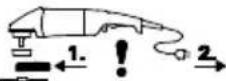
A
aaii aiee iieae
aannn nnnn nn nnnn nnnn nnnn nnnn nnnn nnnn
aayssall ayjdlal yg j aelllll lalil j
aIgSll I galsl gall g jll lgl
(1)
aaii i 1
jia jia jia jia jia jia jia jia jia jia jia jia jia jia jia jia jia jia jia jia jia jia jia jia jia jia jia jia jia jia jia jia jia jia jia jia jia jia jia jia jia jia jia jia jia jia jia jia jia jia jia
y
a 1
1 1
a 100
A
"WE..."
()
aia aiaiaiaiaiaiaiaiaiaiaiaiaiaiaiaiaiaiaiaiaiaiaiaiaiaiaiaiaiaiaiaiaiaiaiaiaiaiaiaiaiaiaiaiaiaiaiaiaiaiaiaiaiaiaiaiaiaiaiaiaiaiaia
.(12)
aia 1
()
Abe yjBaBaaBjllg1yIaBai jSaa (Aaa20 aJb
EC SB
1.11 Jull jbil
:
y
j 1 j j j j j j j j j j j j j j j j j j j j j j j j j j j j j j j j j j j j j j j j j j j j j j j
y
Soll
e b
i j 1
j 1
aill gill boll c gill no gol eolid sic
y j 1
a a a a a a a a a a a a a a a
a 1 gill jg albe plisalie
gill bailly dLwai jSay aJ gannal no kaw jsi
1 1
11 Jall jll lal llll
J 1
1
aaii i 1
auiuui 1aiiuaia i
e i 100
-
a
Jae: aieeall goll jn gill nall Jaeell n gill
aai jia oiaea aayaa o jygi i ci yjg gill
yjgall yjgall claynll jgnll jgall
1 1
-
-
-
-
-
-
-
-
-
-
-
-
-
-
-
-
-
-
-
-
-
-
-
-
-
-
-
-
-
-
-
-
-
-
-
-
-
-
- 40.
-
-
-
-
-
-
-
-
-
-
-
-
-
-
-
-
-
-
-
-
-
-
-
-
-
-
-
-
-
-
-
-
-
-
-
-
-
i j 1jai jai jai jai jai jai jai jai
Jgssssssssssssssssssssssss
iiaii (jio) iisni 1sog iisii all, jieii
jolll jolll jolll jolll
i 1
haill jll
()
(1)

8 8 8 8 8 8 8 8 8 8 8 8 8 8 8 8 8 8 8 8 8 8 8 8 8 8 8 8 8 8 8 8 8 8 8 8 8 8 8 8 8 8 8 8

j 1 j 1 j 1 j 1 j 1 j 1 j 1 j 1 j 1 j 1 j 1 j 1 j 1 j 1 j 1 j 1 j 1 j 1 j 1 j 1 j 1 j 1 j 1 j 1 j 1 j 1 j 1 j 1 j 1 j 1 j 1 j 1 j 1 j 1 j

(7.1 Jall jil) 1Jll d gac uiiy -
(3)jll (1)gill bail al gals
aclll jlac oljil g ydy baaal baill algalu bpr s - 8gai jla jra jy jn c y aall bail algal u pr S - aclll jlac oljil g
sIe iagalldjW...B... aolly o jaoal cllsl 180
:1)
(7.1 Jall jil) jjglal gac ciit y - Aclll w jie olil uSc (1) 1yill bail lalua slay
(j)b#algla 7.4
:14) bai algalo
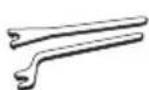
gLaalalolalolalolalolalolalolalolalolalolalolalolalolalolalolalolalolalolalolalol
a(1- 14)
aagaaal llll aae 4 (1) algauu uuuu jai (14) baii ay gaoa eia ybi
14 15
slae aagaaal salyj yaii W...B... aally jaaall cllslall .y10180
:
al golus 7.1 Jaaill jai (15) 14
1.8
1
8.1
jdl 15k jgl 4g 10g

a aie aiee eae
jglal jlaol lal: gall y 1yll ciny

J 1

if we will “WE...” go to all cities
6 6 6 6 6 6 6 6 6 6 6 6 6 6 6 6 6 6 6 6 6 6 6 6 6 6 6 6 6