38155 - Switch Lindy - Free user manual and instructions
Find the device manual for free 38155 Lindy in PDF.
| Product Type | HDMI Splitter-Extender via Cat.6 |
| Brand | Lindy |
| Model | 38155 |
| Transmitter Dimensions | 210 x 83 x 17 mm |
| Each Receiver Dimensions | 79 x 68 x 17 mm |
| Power Supply | 12V DC 2.5A (multi-country included) |
| Power Consumption | 8 W max. |
| Maximum Distance per Cat.6 Link | 50 meters (solid wire cable) |
| Maximum Resolution | Full HD 1080p 60 Hz (4:4:4 8 bpc, 4:2:2 12 bpc) |
| Supported Audio Formats | LPCM, DTS Digital, DTS HD, Dolby Digital, Dolby True HD |
| HDMI Standards | HDMI 1.3, HDCP 1.2, DVI 1.0 |
| IR Function | Frequencies 20-60 kHz, IR transmitter and receivers included |
| Power over Cat.6 (PoC) | Yes, single power supply on transmitter |
| EDID Presets | 9 presets + cloning from local HDMI port |
| Adjustable Equalization (EQ) | Yes, on each receiver according to cable length |
| ESD Protection | ±8 kV (air discharge), ±4 kV (contact) |
| Operating Temperature | 0 to 40 °C |
| Storage Temperature | -20 to 60 °C |
| Relative Humidity | 20-90% RH (non-condensing) |
| Package Contents | 1 transmitter, 4 receivers, power supply, 2 mounting brackets, 1 IR transmitter cable, 4 IR receiver cables, manual |
| Warranty | 2 years (lifetime technical support) |
Frequently Asked Questions - 38155 Lindy
User questions about 38155 Lindy
0 question about this device. Answer the ones you know or ask your own.
Ask a new question about this device
Download the instructions for your Switch in PDF format for free! Find your manual 38155 - Lindy and take your electronic device back in hand. On this page are published all the documents necessary for the use of your device. 38155 by Lindy.
USER MANUAL 38155 Lindy
HDMI Cat.6 Splitter Extender
User Manual
Benutzerhandbuch
Manuel Utilisateur
Manuale
English
Deutsch
Français
Italiano
No.38155
lindy.com
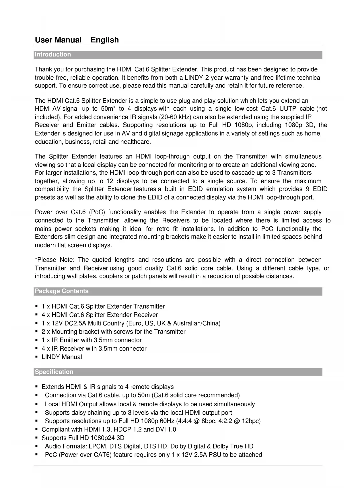
Introduction
Thank you for purchasing the HDMI Cat.6 Splitter Extender. This product has been designed to provide trouble free, reliable operation. It benefits from both a LINDY 2 year warranty and free lifetime technical support. To ensure correct use, please read this manual carefully and retain it for future reference.
The HDMI Cat.6 Splitter Extender is a simple to use plug and play solution which lets you extend an HDMI AV signal up to 50m^* to 4 displays with each using a single low-cost Cat.6 UUTP cable (not included). For added convenience IR signals (20-60 kHz) can also be extended using the supplied IR Receiver and Emitter cables. Supporting resolutions up to Full HD 1080p, including 1080p 3D, the Extender is designed for use in AV and digital signage applications in a variety of settings such as home, education, business, retail and healthcare.
The Splitter Extender features an HDMI loop-through output on the Transmitter with simultaneous viewing so that a local display can be connected for monitoring or to create an additional viewing zone. For larger installations, the HDMI loop-through port can also be used to cascade up to 3 Transmitters together, allowing up to 12 displays to be connected to a single source. To ensure the maximum compatibility the Splitter Extender features a built in EDID emulation system which provides 9 EDID presets as well as the ability to clone the EDID of a connected display via the HDMI loop-through port.
Power over Cat.6 (PoC) functionality enables the Extender to operate from a single power supply connected to the Transmitter, allowing the Receivers to be located where there is limited access to mains power sockets making it ideal for retro fit installations. In addition to PoC functionality the Extenders slim design and integrated mounting brackets make it easier to install in limited spaces behind modern flat screen displays.
*Please Note: The quoted lengths and resolutions are possible with a direct connection between Transmitter and Receiver using good quality Cat.6 solid core cable. Using a different cable type, or introducing wall plates, couplers or patch panels will result in a reduction of possible distances.
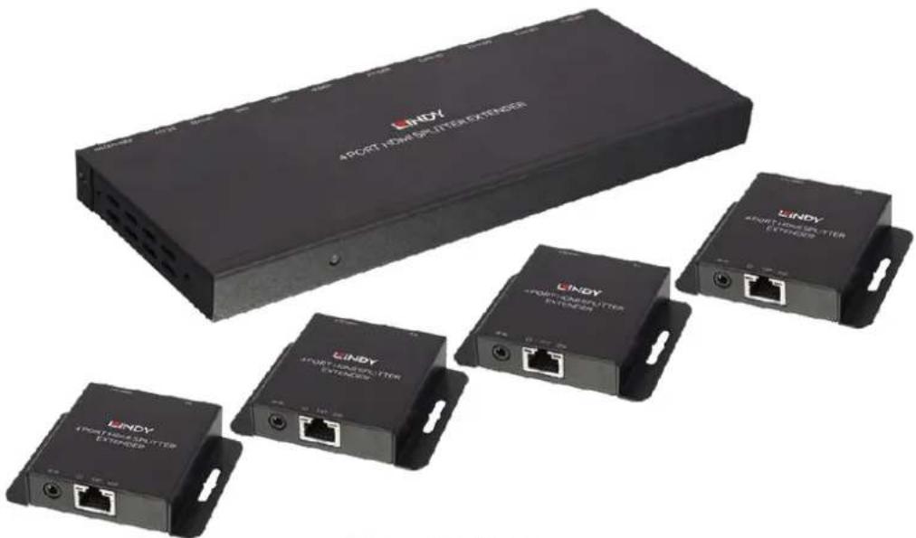
Package Contents
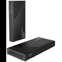
- 1 x HDMI Cat.6 Splitter Extender Transmitter
- 4 x HDMI Cat.6 Splitter Extender Receiver
- 1 x 12V DC2.5A Multi Country (Euro, US, UK & Australian/China)
- 2 × Mounting bracket with screws for the Transmitter
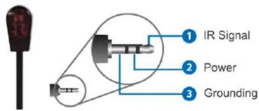
- 1 x IR Emitter with 3.5mm connector
- 4 × IR Receiver with 3.5mm connector
LINDY Manual
Specification
- Extends HDMI & IR signals to 4 remote displays
- Connection via Cat.6 cable, up to 50m (Cat.6 solid core recommended)
- Local HDMI Output allows local & remote displays to be used simultaneously
Supports daisy chaining up to 3 levels via the local HDMI output port
Supports resolutions up to Full HD 1080p 60Hz (4:4:4 @ 8bpc, 4:2:2 @ 12bpc)
Compliant with HDMI 1.3, HDCP 1.2 and DVI 1.0
Supports Full HD 1080p24 3D
Audio Formats: LPCM, DTS Digital, DTS HD, Dolby Digital & Dolby True HD - PoC (Power over CAT6) feature requires only 1 × 12V 2.5A PSU to be attached
Supports 20 - 60kHz IR Frequencies
- Features 9 EDID presets, plus EDID learning from the local HDMI output
- Adjustable EQ to match Cat.6 cable length
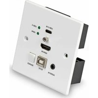
Transmitter ports: HDMI Type A In and Out, 4x CAT6 Out, 3.5mm IR Out & DC Socket
- Receiver ports: HDMI Type A Out, 1x CAT6 In & 3.5mm IR In
Power consumption: 8W Max
ESD Protection: ± 8kV (air-gap discharge)
Human Body Model: ± 4kV (contact discharge)
- Operating temp: approx. 0 to 40^ / Storage temp: approx. -20 to 60^
Relative Humidity: 20 - 90% RH (non-condensing)
Product Dimensions: Transmitter 210x83x17mm / Receivers 79x68x17mm (each)
Overview
Transmitter
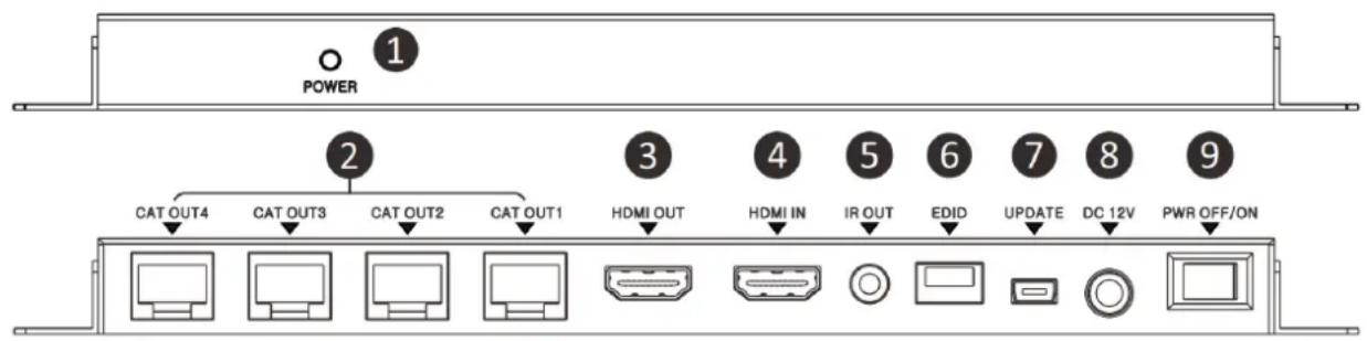
- Power LED: Illuminates when the Transmitter is connected to the power supply and switched on.
- CAT OUT 1-4: Connect to Cat.6 cables to make the connection to the Receiver units.
- HDMI OUT: Connect to a local HDMI display or to another Transmitter unit to cascade to more remote displays.
- HDMI IN: Connect to your HDMI source device using a good quality HDMI cable.
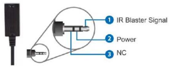
- IR OUT: Connect the supplied IR Emitter.
- EDID: Dip switches to select which EDID is used.
- UPDATE: For updating the Transmitters firmware.
- DC IN: Connect the supplied 12V DC power supply.
- POWER SWITCH: Switch the system (Transmitter and Receiver's) on/off.
Receiver
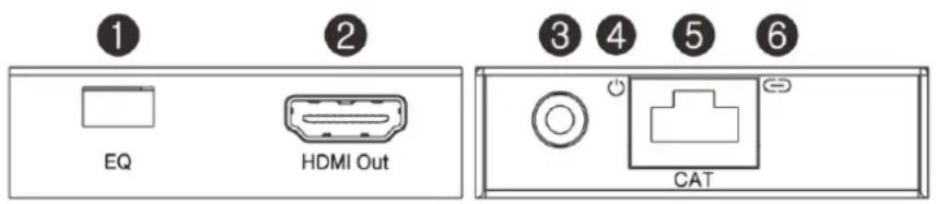
- EQ: Use to adapt the Receiver according to the length of Cat.6 cable being used.
- HDMI OUT: Connect to your HDMI display using a good quality HDMI cable.
- IR IN: Connect the supplied IR Receiver.
- POWER LED: Illuminates green when power is received from the Transmitter.
- CAT: Connect to a Cat.6 cable to make the connection to the Transmitter.
- LOCK LED: Illuminates orange when a stable signal is received from the Transmitter.
IR Receiver IR Emitter

Installation
Important! If you want to lay cables inside a cable duct or through a wall, please test your Cat.6 cables in a test installation at the highest desired resolution/colour space/colour depth combination with the extender BEFORE you install them in your wall or cable duct!
The following steps are for an installation using HDMI equipment, if you are using DVI equipment, please substitute the HDMI cables for DVI to HDMI cables where required.
- Connect your HDMI source to the Transmitter unit using a HDMI cable (maximum length 3m).
- Connect one end of the Cat.6 cable (max. length 50m) to the CAT OUT 1-4 ports on the Transmitter and the other end to a CAT port on each of the Receivers. We strongly recommend the use of solid core Cat.6 installation cable.
- Set the EQ on each of the Receivers to the setting which matches the Cat.6 cable length (see table below), either the Primary or Secondary may be used depending on picture and cable quality (Black squares denote the location of the dip switch).
| Cable Length | Primary Setting | Secondary Setting | Cable Length | Primary Setting | Secondary Setting |
| Under 15m (49.5ft) | 30 – 40m (99 – 132ft) | ||||
| 15 – 30m (49.5 – 99ft) | 40 – 50m (132 – 164ft) |
- Use another HDMI cable (maximum length 3m) to connect an HDMI display device to the HDMI output port on each Receiver unit.
- An additional HDMI display can be connected to the HDMI Out port of the Transmitter if required for local monitoring or cascading to an additional Transmitter.
- Set the EDID Switch according to your requirement, see the EDID table in the operation section of this manual.
- For additional Infrared remote signal functionality, connect the included IR Extension Cables to the Transmitter and Receiver units, using the IR Emitter with the IR Out port on the Transmitter and the IR Receiver with the IR In port of the Receivers.
- Place the IR Emitter in front of the IR Port of the equipment you want to control, and ensure you place the IR Receivers in a location where they may easily receive the signal of your IR remote.
- Power on your HDMI Source and Display to complete the installation.
- Finally plug the DC power supply into the Transmitter unit and set the Power Switch to On, the Power LED will illuminate on all units.
Operation
The Splitter Extender uses preset EDID values as defined in the table below, allowing you to configure the Extender to work correctly with the capabilities of your HDMI equipment. In total there are 9 presets using different resolution, scan and audio values for you to choose from, alternatively you may use the EDID of the display connected to the HDMI Out port of the Transmitter unit. Each time a change is made to the EDID setting the Transmitter must be power cycled, in some cases it may also be necessary to power cycle the source device too. (Black squares denote the location of the dip switch).
| Position | EDID Description | Position | EDID Description | |
| 1080p, 2 Channel Audio | 1080i, HD Audio | |||
| 1080p, Dolby/DTS 5.1 Channels | 3D, 1080p, 2 Channel Audio | |||
| 1080p, HD Audio | 3D, 1080p, Dolby/DTS 5.1 Channels | |||
| 1080i, 2 Channel Audio | 3D, 1080p, HD Audio | |||
| 1080i, Dolby/DTS 5.1 Channels | Copy from the display connected to HDMI OUT |
Troubleshooting
There is no display on the screen.
- Check that the DC plug and jack used by external power supply is firmly connected and that the Power LED on both the Transmitter and Receivers are illuminated.
- Check that the Cat.6 cables are seated correctly and that the Lock LED on is illuminated on all Receivers.
- Power off all the devices, then power on in this order: first, the Transmitter unit, followed by the display(s) and finally the source.
- For some HDMI devices it may be helpful to unplug and replug their HDMI connection to re-initiate the HDMI handshake and recognition.
- Check that the EQ setting matches the Cat.6 cable length being used. If the primary EQ setting does not work, please try the secondary setting for the length of Cat.6 cable being used.
- Reduce the length of Cat.6 or HDMI cable used, or use a higher quality cable.
Einführung
IR Receiver IR Emitter

Installation
This equipment complies with the requirements relating to Electromagnetic Compatibility Standards. It has been manufactured under the scope of RoHS compliance.
This equipment has been tested and found to comply with the limits for a Class B digital device, pursuant to part 15 of the FCC Rules. These limits are designed to provide reasonable protection against harmful interference in a residential installation.
You are cautioned that changes or modification not expressly approved by the party responsible for compliance could void your authority to operate the equipment.
This device complies with part 15 of the FCC Rules.
Operation is subject to the following two conditions:
- This device may not cause harmful interference, and
- This device must accept any interference received, including interference that may cause undesired operation.
WEEE (Waste of Electrical and Electronic Equipment), Recycling of Electronic Products
Europe, United Kingdom
In 2006 the European Union introduced regulations (WEEE) for the collection and recycling of all waste electrical and electronic equipment. It is no longer allowable to simply throw away electrical and electronic equipment. Instead, these products must enter the recycling process.
Each individual EU member state has implemented the WEEE regulations into national law in slightly different ways. Please follow your national law when you want to dispose of any electrical or electronic products. More details can be obtained from your national WEEE recycling agency.