
GW90872 - Home automation Gewiss - Free user manual and instructions
Find the device manual for free GW90872 Gewiss in PDF.

| Brand | Gewiss |
| Model | GW90872 |
| Product type | KNX/DALI gateway for home automation |
| Usage | DALI lighting control via KNX bus |
| Maximum number of DALI ballasts | 64 |
| Maximum number of DALI groups | 16 |
| Maximum number of DALI scenes | 16 |
| Passive binary inputs | 2 inputs (B1, B2) for switches, push buttons or motion detectors (8-26 Vac / 9-32 Vdc) |
| Display | LCD screen 2 lines of 12 characters |
| Signal LED | PWR (green) and ERR (red), KNX programming LED |
| Power supply | 110-240 Vac, 50/60 Hz, max 0.1 A + KNX bus 24 Vdc SELV |
| Dimensions (L x H x D) | 106 x 55 x 86 mm |
| Weight | 200 g |
| Mounting | On DIN rail 35 mm (6 modules) |
| Protection rating | IP20 |
| Protection class | I (IEC 1140) |
| Overvoltage category | III |
| Operating temperature | 0 °C to +45 °C |
| Storage temperature | -25 °C to +70 °C |
| Relative humidity | 5% to 93% (without condensation) |
| Connectors | KNX bus (standard connector), DALI, binary inputs, power supply (screw terminals) |
| Programming | Locally via MOVE, Prg/Set, ESC buttons and LCD menu, or via ETS software |
| Safety | Compliant with IEC 64-8, EN 50081-1, EN 50082-2, EN 50090-2-2; CE marking |
| Certification | KNX/EIB |
| Housing material | LEXAN plastic UL-94-V0 |
| Maintenance and cleaning | No specific maintenance. Clean with a dry, lint-free cloth. |
| Spare parts and repairability | No user-serviceable parts. In case of malfunction, contact Gewiss technical support. |
Frequently Asked Questions - GW90872 Gewiss
User questions about GW90872 Gewiss
0 question about this device. Answer the ones you know or ask your own.
Ask a new question about this device
Download the instructions for your Home automation in PDF format for free! Find your manual GW90872 - Gewiss and take your electronic device back in hand. On this page are published all the documents necessary for the use of your device. GW90872 by Gewiss.
USER MANUAL GW90872 Gewiss
Gateway KNX/DALI 64/16
KNX/DALI Gateway 64/16
text_image
D4-0-B1 B1B2 B2 Move Digital EXO PMR EXR DA 90-87 GNX® 888 GaNay MNO Data-SAT6 CEGW90872


text_image
Cross-sectional diagram of a cable showing internal twisted and twisted insulation layers with numbered annotations1 Cavo bus
text_image
Technical diagram of a mechanical component with labeled parts ① and ②CERCA BALL. via P-MODE
CERCA BALL. via P-MODE
CANCELLATI BALL: 3
NUOVI BALL: 1
CANC./NUOVI BALL: 3/1
SCENA01 XXXX XXXXXXXXXXXX
The safety of this appliance is only guaranteed if all the instructions given here are followed scrupulously. These should be read thoroughly and kept in a safe place.
The Chorus products must be installed in compliance with the requisites of standard CEI 64-8 for devices for domestic use and similar, in non-dusty atmospheres and where special protection against water penetration is not required.
The GEWISS sales organisation is at your disposal for clarifications and technical information.
Gewiss SpA reserves the right to make changes to the product described in this manual at any time and without giving any notice.
2 PACK CONTENT
The delivery package of the Gateway KNX/Dali contains the following components:
N.1 Device KNX/DALI Gateway 64/16
N.2 shrink sleeve for supplementary insulation of the bus wires
N.1 Installation instructions
3 GENERAL DESCRIPTION
The KNX/DALI Gateway allows communication between the ballasts that implement the DALI protocol (specifically for lighting control), and the KNX Home and Building Automation system; the DALI installations can benefit from the wide range of KNX user interfaces, like command sensors and system display/supervision devices.
The Gateway serves both as DALI-Master device and power supply to all connected ECGs. Up to 64 ballast allocated to up to 16 different groups can be connected per single Gateway. Additionally, up to 16 lighting scenes can be created from the different groups.
The light intensities and failure warnings are available as status objects and can be visualized using any corresponding EIB/KNX display device.
The commissioning of the DALI Gateway (assignment of the ballasts to the various groups) is carried out via the programming button keys and display directly on the device; the setting of the various parameters and the programming of the scenes can be carried out via the buttons keys and display or, alternatively, using the ETS software. Scenes that have already been programmed can subsequently be changed at any time on the device.
Finally, in addition to the EIB/KNX and the DALI interface, there are two binary inputs available on the device for connecting conventional switches, pushbuttons or movement sensors. This allows commissioning, test and operation of the DALI ECGs without the connection of the device to the EIB/KNX network.
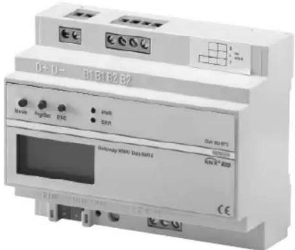
The KNX/DALI Gateway is a 6-module DIN device assembled on a 35mm DIN rail.
The DALI BUS, mains power supply, and binary inputs are connected via special screw connectors, while the standard connector is used for the KNX line.
The connectors as well as the KNX/EIB programming button and LED are only accessible once the cover of the distribution panel removed. The operation of the programming buttons (MOVE, Prg/Set, ESC), the control LEDs (PWR and ERR) as well as the menu display are accessible even with closed cover.
text_image
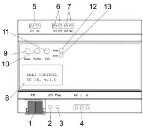
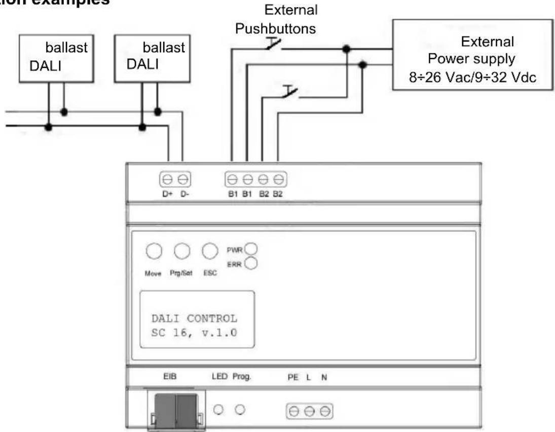
5 6 7 12 13 D+ D- B1 B1 B2 B2 9 Move PprSet CSG PWR ERR DALI CONTROL SC 16, v.1.0 8 EB LED Prop FE L N 1 2 3 4At the lower side of the casing the following connectors can be found (left to right):
- KNX bus connector
- KNX Programming LED
- KNX Programming button
- Power Supply
At the upper side of the casing the following connectors can be found (left to right):
- DALI connector
- Connector passive binary input 1
- Connector passive binary input 2
On the device front the following elements can be found:
-
Display 2x12 chars for DALI commissioning
-
Move button
-
Prg/Set button
-
ESC button
-
Operating LED (PWR)
-
Failure LED (ERR)
4 INSTALLATION

WARNING: the installation of the device must be exclusively done by qualified personnel, following the regulations in force and the guidelines for KNX/EIB installations.
Warnings for KNX/EIB installations
- The length of the bus line between the KNX/DALI Gateway unit and the power supply unit must not exceed 350 metres.
- The length of the bus line between the KNX/DALI Gateway unit and the most distant KNX/EIB device must not exceed 700 metres.
- If possible do not create ring circuits so as to prevent undesirable signals and overloads.
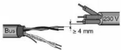
- Keep a distance of at least 4 mm between the individually insulated cables of the bus line and those of the electric line.
text_image
Bus ≥ 4 mm 230 V- Do not damage the electrical continuity conductor of the shielding.
text_image
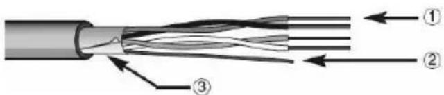
Cross-sectional diagram of a multi-core cable showing internal twisted insulation and insulation layers with numbered annotations.1 Bus cable
2 Electrical continuity conductor
3 Shield

WARNING: the unused bus signal cables and the electric continuity cable must never touch powered elements or the grounding cable!
Warnings for installation phase
The Gateway KNX/DALI is designed to be mounted within distribution panels equipped with 35mm DIN rails. After simply snapping the device onto the rail, the DALI bus should be connected first.
The DALI Control wires can be part of a 5-stranded cable also carrying the ballast power according to IEC90929 (the base insulation is sufficient).
However each wire must be clearly marked and reliably identified.
The maximum cable length for one entire DALI segment must not exceed 300m.
ELECTRICAL CONNECTIONS
WARNING: disconnect the network voltage before connecting the device to the power network!
For electrical connection diagrams, see the following examples.
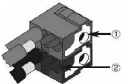
- Connect the bus cable's red wire to the terminal's red connector (+) and the black wire to the black connector (-). Up to 4 bus lines (wires of the same colour in the same connector) can be connected to the bus terminal.
text_image
Technical diagram of a mechanical component with labeled parts ① and ②1 Bus device connection
2 Bus cable connection
- Insulate the screen, the electrical continuity conductor and the remaining white and yellow wires of the bus cable (should a bus cable with 4 conductors be used), which are not needed.
Connection examples
flowchart
graph TD
    A["ballast DALI"] --> B["External Pushbuttons"]
    C["ballast DALI"] --> B
    D["D+ D-"] --> E["DALI CONTROL SC 16, v.1.0"]
    F["B1 B1 B2 B2"] --> E
    G["PWR ERR"] --> E
    H["EIB"] --> I["LED Prog. PE L N"]
    J["External Power supply 8÷26 Vac/9÷32 Vdc"] --> B
After connecting the DALI control wires, the optional external pushbuttons can be connected. The binary inputs are passive meaning that an auxiliary 8-26VAC or 9-32V DC voltage is required to operate
the switches.
It is now possible to connect the 110-240 VAC 50/60 Hz power supply to the lower right connector block according to the printed schema.
The KNX BUS cable is connected using the BUS terminal supplied.
For proper insulation from the power block, it is necessary to wrap the EIB control wires from the cable end right to the EIB connector with the shrink sleeve that is part of the package.
After complete connection of the device and activation of the power supply, the device will display its product name and the firmware version.
The flashing green "PWR" LED shows that the device is ready. If the device is started up without being connected to the KNX BUS, the red "ERR" LED will light up.
If the red "ERR" LED is still lit up after you have connected the KNX terminal and checked there is a power supply to the line, then there is probably a short-circuit on the DALI segment (refer to the SYSTEM TEST submenu). In this case, remember to check the DALI segment wiring.
5 PROGRAMMING
Application program
The KNX database can be downloaded from the website www.Gewiss.com, details regarding the configuration are involved on the Technical Manual.
Physical address programming
1 Power up the device using the bus.
2 Press the programming button to set the Gateway KNX/Dali to load the physical address from ETS.
Both Main Supply and bus power are requie to set the device via ETS.
5.1 Operation and Menu Structure
The connected DALI segment can entirely be commissioned with the three programming buttons (MOVE, Prg/Set, ESC).
Optional DALI parameters can also be set or changed with these buttons.
The use of the button keys is context-specific for the current menu.
Depending on the selected menu, it is possible to access up to two submenu levels.
The current menu item is shown on the display.
The user navigates within the menu with short pushes of the buttons: the MOVE button selects the next menu item within each level.
A short push on the Prg/Set button selects the submenu, if it exists.
The ESC button quits the current menu level and returns to the parent menu item.
Main Menu – Level 1
The main menu is structured as follows:

DALI CONTROL SC 16, V.1.0
The product description and the fi rmware version are displayed.
This screen features a submenu that allows to select the display language.
NEW- INSTALLATION
This screen features submenus which will reset all connected DALI ECGs and will start an automatic detection of connected devices.
This is the preferred choice for a new installation.
POST INSTALLATION
This screen features submenus that allow to resynchronize DALI ECGs after a post install (adding or removing ECGs to a previously configured DALI Gateway) by starting an automatic detection and displaying the modified configuration.
GROUP ASSIGNMENT
Within the submenus of this screen, the detected ECGs can be allocated to the desired DALI groups.
GROUP PARAMETERS
Within the submenus of this screen, the parameters of each group can be set and modified.
SCENE ASSIGNMENT
The submenus of this screen allow to add DALI groups to DALI scenes.
GROUP TEST
The submenus of this screen allow to switch the entire DALI segment (Broadcast) or individual DALI groups for testing purposes.
TEST SCENES
This screen features submenus to invoke individual DALI scenes for testing purposes.
SYSTEM TEST
This screens leads to submenus that will display all existing system failures individually.
FUNCTION INPUT B1
The submenus of this screen allow to set the function of the binary input B1.
FUNCTION INPUT B2
The submenus of this screen allow to set the function of the binary input B2
If a function is to be activated or a parameter to be changed within a given submenu, it is necessary to switch to the so called programming mode by pushing the Prg/Set button for more than 2 seconds.
Once the selected function of parameter is in programming mode, an Arrow symbol appears in the display. Once the programming mode is active, the MOVE button is used to change the setting or the parameter value. By pressing the Prg/Set button with a short push again, the programming mode is ended (EXIT and SAVE). the parameter has been updated with the selected value, or the selected function has been activated.
The ESC button quits the programming mode without saving.
Submenu DALI CONTROL – Level 2
DALI CONTROL SC 16, V.1.0
The level 1 menu DALI CONTROL leads to the submenu LANGUAGE by pressing the Prg/Set key with a short push.
LANGUAGE -> ENGLISH
The MOVE button
The currently active language is displayed within the submenu. A long push of the Prg/Set button switches the device to programming mode navigates through the available languages: ITALIAN, GERMAN, ENGLISH, FRENCH, SPANISH, DUTCH. Pressing the Prg/Set button with a short push this time, the new language is activated and the display changes accordingly. The default language on shipment is ITALIAN.
Submenu NEW INSTALLATION – Level 2
NEW INSTALLATION
A short push on the Prg/Set key leads from level 1 menu NEW INSTALLATION to the submenu SEARCH ECG via P-MODE.
SEARCH ECGs via P-MODE
A long push of the Prg/Set button switches the device to programming mode. Another push, but a short one this time, starts the initialisation and search processes.
First, all ECGs connected to this DALI Segment are reset automatically, all previously assigned groups and parameters are deleted. Secondly, all ECGs are searched for by their randomly generated long address and identified in ascending order.
FOUND ECGs: 47
The search process can require several minutes depending on the number of connected ECGs. After completion of the search process, the number of discovered ECGs is shown on the display. By pushing the ESC button or by simply waiting for more than 30 seconds, the parent menu item is again activated.
Submenu POST INSTALLATION – Level 2
POST INSTALLATION
A short push on the Prg/Set key leads from level 1 menu POST INSTALLATION to the submenu SEARCH ECG via P-MODE
SEARCH ECGs via P-MODE
A long push of the Prg/Set button switches the device to programming mode. Another push, but a short one this time, starts the verification and search process. The connected ECGs are searched for by their long addresses.
DELETED ECGs: 3
The result is compared with the previous configuration. If ECGs have been removed from the DALI-Segment, their corresponding entries and settings are automatically deleted from the DALI Gateway. During the verification process, the number of deleted ECGs is summarized on the display.
NEW ECGs: 1
The Gateway then searches for new ECGs within the DALI-Segment.
New ECGs are automatically reset and all previously assigned parameters are deleted. The search process can require several minutes depending on the number of connected ECGs. During the search process, the number of new ECGs that are discovered is summarized on the display.
DEL./NEW ECGs: 3/1
After completion of the verification and of the search process, the number of deleted and new ECGs are shown on the display (# deleted ECGs on the left / # new ECGs on the right). By pushing the ESC button or by simply waiting for more than 30 seconds, the parent menu item is again activated.
Submenu GROUP ASSIGNMENT – Level 2 and 3
GROUP ASSIGNMENT
A short push on the Prg/Set key leads from level 1 menu GROUP ASSIGNMENT to a submenu allowing to assign ECGs to one of the 16 DALI groups.
Within the submenu, it is possible to create new assignments for ECGs or to modify existing ones.
ECG No.: 12 GROUP: --
By briefly pressing the "Move" button key, you can move from one ballast to the next. The first row of the display shows the number of the current ballast.
The lamp connected to the ballast will flash as long as the latter remains selected. This allows you to easily identify which number is assigned to which lamp.
ECGS No: 12 GROUP: 01
A long push of the Prg/Set button switches the device to programming mode. By briefly pressing the "Move" button key, you can select the group to which the ballast must be assigned. Once the assignment is complete, briefly press the "Prg/Set" button key to confirm and save it.
In a new installation, this assignment must be completed for each ballast identified during the research process. By pushing the ESC button or by simply waiting for more than 30 seconds, the parent menu item is again activated.
GROUP PARAMETERS submenu – Levels 2 and 3
GROUP PARAMETERS
By briefly pressing the "Prg/Set" button key, you can move from the first level "GROUP PARAMETERS" menu to a submenu that lets you set all the parameters of a DALI group.
You are advised to set the parameters of the group in the ETS application, and to only use this function for any quick modifications of the individual settings.
Please remember that every download of the ETS application will overwrite the settings imposed with this submenu.
GROUP: 01 PARAMETERS
By briefly pressing the "Move" button key, you can move from one group to the next. The first row of the display shows the number of the current group.
By keeping the Prg/Set button key pressed, you can commute the device to programming mode; the type of parameter (with relative value) will be shown on the second line of the display.
The following parameters can be modified directly from the device:
GROUP: 12 ON VALUE:100
- Initial (ON) Value: 0 to 100% in 5% steps
- Lower Dimming Limit (MIN DIM): 0 to 40% in 5% steps
- Upper Dimming Limit (MAX DIM): 50 to 100% in 5% steps
- Dimming Duration for 0..100%: 5 sec. to 60 sec.
GROUP: 12
MIN DIM.: 0
Once the programming mode is active, the first parameter (ON VALUE) is displayed. The parameter value can be changed with a short push of the MOVE button. If no modification is necessary, do not use the "Move" button key. By briefly pressing the Prg/Set button key, you can save the parameter value and jump to the next parameter in this group (MIN DIM), which can also be modified if necessary.
GROUP: 12
MAX DIM:100
By briefly pressing the Prg/Set button key again, you can save the parameter value and jump to the next parameter in this group (MAX DIM), which can also be modified if necessary. By briefly pressing the Prg/Set key again, you can save the parameter value and jump to the next parameter in this group (DURATION), which can also be modified if necessary.
GROUP: 12
DURATION:10s
By briefly pressing the "Prg/Set" button key, you can save the value and jump to the first parameter (ON VALUE). By pushing the ESC button or by simply waiting for more than 30 seconds, the parent menu item is again activated.
Submenu SCENE ASSIGNMENT – Level 2 and 3
SCENE
ASSIGNMENT
By briefly pressing the "Prg/Set" button key, you can move from the first level "SCENE ASSIGNMENT" menu to a submenu that lets you associate the DALI groups with one or more of the 16 available DALI scenes.
SCENE01 XXXX
XXXXXXXXXXXXXX
By briefly pressing the "Move" button key, you can move from one scene to the next. The first row of the display shows the number of the current scene.
The symbols show which of the 16 groups are associated with this scene.
An 'X' in the corresponding field means the group is part of the scene, while a '-' sign means it is not. The four characters that follow the scene number represent the groups from 1 to 4, while the 12 characters on the second row represent the groups from 5 to 16.
SCENE03 ----
XXXX----XX
A long push of the Prg/Set button switches the device to programming mode. The flashing cursor on the first 'X' indicates that Group 1 is currently selected. By briefly pressing the "Prg/Set" button key, you can choose whether to assign the group to the scene, alternating between associated element ('X') and non-associated element ('-'). By briefly pressing the "Move" button key, you can move the cursor on to the next group, which can also be associated if necessary with the scene via the "Prg/Set" button key. And so on for all the other groups. Once all 16 groups have been examined, the configuration is saved and becomes active as soon as the scene is recalled. After examining the last group, this submenu is automatically closed and the device goes back to the previous menu item. To cancel the modifications, do not complete the association of the groups and use the "ESC" button key, or wait about 30 seconds.
GROUP TEST submenu – Levels 2 and 3
GROUP
TEST
By briefly pressing the "Prg/Set" button key, you can move from the first level "GROUP TEST" menu to a submenu that lets you commute between the DALI groups individually or globally (via broadcast), to check the functioning of the ballasts.
GROUP:06 TEST
By briefly pressing the "Move" button key within the submenu, you can move from one group to the next. The first row of the display shows the number of the current group.
GROUP: 06 ->off
A long push of the Prg/Set button switches the device to programming mode By briefly pressing the "Move" button key, you can select the required command (options ->on" or ->off"), while by briefly pressing the "Prg/Set" button key, the command is implemented. By pressing the "ESC" button key, or simply waiting about 30 seconds, the operation is cancelled and the previous menu reappears.
TEST SCENES submenu – Levels 2 and 3
TEST SCENES
By briefly pressing the "Prg/Set" button key, you can move from the first level "TEST SCENES" menu to a submenu that lets you both execute each DALI scene individually (to check they function) and save the current lighting settings, associating them with a specific scene.
SCENE No.:02 TEST
By briefly pressing the "Move" button key within the submenu, you can move from one scene to the next. The first row of the display shows the number of the current scene.
SCENE No :02 ->invoke
A long push of the Prg/Set button switches the device to programming mode By briefly pressing the "Move" button key, you can select the required command (options ->invoke" or ->save" scene), while by briefly pressing the "Prg/Set" button key, the command is implemented.
By pressing the "ESC" button key, or simply waiting about 30 seconds, the operation is cancelled and the previous menu reappears.
SYSTEM TEST submenu – Levels 2 and 3
SYSTEM TEST
By briefly pressing the "Prg/Set" button key, you can move from the first level "SYSTEM TEST" menu to a submenu that lets you display all the error messages individually.
DALI fault
The display will show any errors.
The following error types are recognised, visualised on the display, and also signalled by the fi xed light of the red "ERR" LED:
LAMP fault: E 23
- short-circuit on the DALI BUS
- lamp fault with indication of the number of the ballast to which it is connected
- ballast fault with indication of the relative number
- no KNX BUS power supply
ECG
fault: E 34
A short-circuit on the DALI BUS prevents the device recognising any other fault that may arise. By contrast, all other error types can be identified simultaneously. By briefly pressing the "Move" button key within the submenu, you can move from one error condition to another.
Errors concerning the lamps or ballasts will show the number associated with the ballast, so the error can immediately be located in the installation.
By pushing the ESC button or by simply waiting for more than 30 seconds, the parent menu item is again activated.
KNX
fault
FUNCTION INPUT B1 submenu – Levels 2 and 3
FUNCTION
INPUT B1
By briefly pressing the "Prg/Set" button key, you can move from the first level "FUNCTION INPUT B1" menu to a submenu that lets you assign the function to the conventional button key or to the presence detector connected to the B1 binary input.
B1: TOG/DIM
ASSIGNMENT
By briefly pressing the "Move" button key, you can move from one function to the next. The first row of the display shows the current function. The following functions are available:
• ON: a switch-on command is sent.
- OFF: a switch-off command is sent.
- TOGGLE pushbutton toggles between ON and OFF
- ON/DIM: the brief closure of the contact causes a switch-on command to be sent; prolonged closure causes an increase in light intensity and the consequent adjustment stop command when the contact reopens.
- OFF/DIM: the brief closure of the contact causes a switch-off command to be sent; prolonged closure causes a reduction in light intensity and the consequent adjustment stop command when the contact reopens.
- TOG/DIM short push toggles between ON and OFF, long push dims up or down and issues a stop telegram when pushbutton is released. (Single Button Dimming)
• SCENE pushbutton invokes a scene
B1: ON
ALL GROUPS
A long push of the Prg/Set button switches the device to programming mode. By briefly pressing the "Move" button key, you can select the group or scene with which the function must be associated. By briefly pressing the "Prg/Set" button key, you can confirm the selection and quit the submenu. By pressing the "ESC" button key, or simply waiting about 30 seconds, the operation is cancelled and the previous menu reappears.
B1: TOG/DIM
GROUP: 07
FUNCTION INPUT B2 submenu – Levels 2 and 3
FUNCTION
INPUT B2
By briefly pressing the "Prg/Set" button key, you can move from the first level "FUNCTION INPUT B2" menu to a submenu that lets you assign the function to the conventional button key or to the presence detector connected to the B2 binary input.
B2: SCENE ASSIGNMENT
By briefly pressing the "Move" button key, you can move from one function to the next. The first row of the display shows the current function. The following functions are available:
- ON: a switch-on command is sent.
- OFF: a switch-off command is sent.
- TOGGLE: pushbutton toggles between ON and OFF
- ON/DIM: the brief closure of the contact causes a switch-on command to be sent; prolonged closure causes an increase in light intensity and the consequent adjustment stop command when the contact reopens.
- OFF/DIM: the brief closure of the contact causes a switch-off command to be sent; prolonged closure causes a reduction in light intensity and the consequent adjustment stop command when the contact reopens.
- TOG/DIM short push toggles between ON and OFF, long push dims up or down and issues a stop telegram when pushbutton is released. (Single Button Dimming)
- SCENE pushbutton invokes a scene
B2: SCENE SCENE: 03
A long push of the Prg/Set button switches the device to programming mode. By briefly pressing the "Move" button key, you can select the group or scene with which the function must be associated. By briefly pressing the "Prg/Set" button key, you can confirm the selection and quit the submenu. By pressing the "ESC" button key, or simply waiting about 30 seconds, the operation is cancelled and the previous menu reappears.
5.2 First installation of a DALI segment
As soon as the wiring of the device is completed in compliance with the instructions given in this document, the DALI segment can be directly commissioned with the KNX/DALI Gateway, independently of the KNX system. As long as the KNX BUS is not connected, the red "ERR" LED will remain lit up; despite this, the commissioning of the DALI segment can still continue. The steps to be carried out are:
- In a new installation, it is necessary to begin with a search for all the DALI ballasts connected, using the "NEW INSTALLATION" menu. Once all the devices have been identified, the display will show the letters (ESC) next to the number of devices located. This invites the user to press the "ESC" button key to quit this menu (giving him, however, the possibility to read or note the number of recognised devices).
- Secondly, each of the devices identified must be assigned to a DALI group using the "GROUP ASSIGNMENT" menu. Standard commissioning is now complete.
Test: using the "GROUP TEST" menu, it is possible to send switch-on/off commands to the individual groups, to test the functioning of the lamps.
Optional settings:
- If there are any devices connected to the binary inputs of the KNX/DALI Gateway, the "FUNCTION INPUT B1" or "FUNCTION INPUT B2" menu will let you select the required function for each input.
This allows standard functioning of the DALI segment, even if the KNX BUS is not operating (e.g. during site construction).
The binary inputs can then act as a system component, for example to connect the presence detectors, movement detectors or simply the conventional switches or push-buttons. - Finally, it is possible to assign the various DALI groups to the DALI scenes, using the "SCENE ASSIGNMENT" menu.
In this way, the commissioning of the DALI segment is completed. The programming and commissioning of the KNX line can be started up from this point on, using the ETS program and the relative program of the KNX/DALI Gateway 64/16.
6 TECHNICAL DATA
Electrical Safety
- Pollution Degree: 2
• Protection (EN 60529): IP20
• Protection Class: (IEC 1140) I
• Overvoltage Category: III - Bus: SELV DC 24 V
EMC-Compliance
Complies with EN 50081-1 and EN 50082-2, EN 50090-2-2
Environmental
- Operating Temperature: 0^ to +45^
• Storage Temperature: -25°C to +70°C
• Rel. Humidity (non condensing): 5 % to 93 %
Certification
KNX/EIB registered
CE-Signage
According to EMC recommendations (domestic and commercial buildings), low voltage recommendations
Mechanical Data
• Casing: Plastic LEXAN UL-94-V0
• Measurements of casing: Width: 106mm, Height: 55mm, Length: 86mm
- Weight: 200 g
- Mounting: on 35mm DIN rail
Operating Elements
- Programming Button to toggle between normal and addressing mode
- 3 buttons (MOVE, Prg/Set, ESC) on display front to commission the device and set parameters
Display Elements
- Red LED to indicate EIB/KNX Normal-/Addressing Mode
- Green PWR-LED to signal device readiness (blinks when in normal operation mode)
- Red ERR-LED to signal fault status
- LC-Display, 2 lines with 12 characters each with menu for commissioning and setting of parameters.
Inputs
- 2 x passive binary input for connection of conventional pushbutton or presence detector 9-32VDC or 8-26VAC, max wire length 15m
DALI-Bus
- Connection of up to 64 ECGs complying to IEC 60926
• DALI-Voltage 18-21VDC, short circuit proof - It is not allowed to use other control devices (DALI-Master devices) within the same line.
Power Supply
• Power Supply 110 to 240 V, 50 to 60Hz, max. 0,1A
• Additional Power Supply via the EIB Bus
Connectors
• EIB bus connector
- Power Supply: screw connector 3x 1,5mm ^2 single or threaded core
- DALI-Bus: screw connector 2x 1,5mm ^2 single or threaded core
- Binary input: screw connector 2x 1,5mm ^2 single or threaded core
Francais
1 AVERTISSEMENTS GÉNÉRAUX 34
2 CONTENU DE LA CONFECTION 34
3 DESCRIPTION GENERALE 35
4 INSTALLATION 36
5 PROGRAMMATION 38
text_image
Cross-sectional diagram of a cable showing internal twisted insulation and labeled parts ①, ②, and ③text_image
Technical diagram of a mechanical component with labeled parts ① and ②SCÉNE01 XXXX XXXXXXXXXXXX
text_image
Cross-sectional diagram of a cable showing internal twisted insulation and insulation layers with numbered annotationstext_image
Technical diagram of a mechanical component with labeled parts ① and ②ESCE.01 XXXX XXXXXXXXXXXX