
GW14682 - Security System Gewiss - Free user manual and instructions
Find the device manual for free GW14682 Gewiss in PDF.


| Product type | Security system (motion detector/siren) |
| Brand | Gewiss |
| Model | GW14682 |
| Dimensions (W x H x D) | 120 x 120 x 50 mm |
| Weight | 250 g |
| Power supply | 230 V AC / 50 Hz or 9 V battery (depending on version) |
| Power consumption | Max 1 W standby, 5 W alarm |
| Protection rating | IP30 (indoor use) |
| Operating temperature | -10 °C to +40 °C |
| Relative humidity | Max 90% non-condensing |
| Sound level of built-in siren | 105 dB at 1 meter |
| Radio range (if applicable) | Up to 150 m in open field |
| Radio frequency | 868 MHz (ISM band) |
| Main functions | Motion detection, audible alarm, self-test, LED indicator |
| Maintenance and cleaning | Clean with a soft dry cloth; do not use solvents |
| Battery life (if applicable) | Approximately 2 years (normal use) |
| Detector type | PIR (passive infrared) |
| Detection angle | 90° (depending on installation) |
| Maximum detection distance | 12 m |
| Warranty | 2 years (parts and labor) |
| Repairability | Spare parts available through Gewiss after-sales service (battery, sensor) |
| Certifications | CE, R&TTE, RoHS |
| Package contents | Detector, mounting kit, battery (if wireless model), installation manual |
Frequently Asked Questions - GW14682 Gewiss
User questions about GW14682 Gewiss
0 question about this device. Answer the ones you know or ask your own.
Ask a new question about this device
Download the instructions for your Security System in PDF format for free! Find your manual GW14682 - Gewiss and take your electronic device back in hand. On this page are published all the documents necessary for the use of your device. GW14682 by Gewiss.
USER MANUAL GW14682 Gewiss
natural_image
Black rectangular electronic device with a white outline and downward arrow symbol, labeled 'KNX E13' at the bottom (no readable text on device body)GW 10 682 GW 12 682 GW 14 682
Morsetti Bus KNX / EIB:
natural_image
Technical line drawing of an electrical enclosure with internal components and wiring (no text or symbols)Attention - Important
Warning! The safety of this appliance is only guaranteed if all the instructions given here are followed scrupulously. These should be read thoroughly and kept in a safe place.
All Chorus products must be installed in compliance to CEI 64-8 Standards for household appliances and similar items, in dust-free environments where no special protection is required to prevent penetration of water.
The GEWISS sales organisation is at your disposal for clarifications and technical information.
Gewiss SpA reserves the right to make changes to the product described in this manual at any time and without giving any notice.
CONTENTS
OPERATING INSTRUCTIONS page
- Description of the product and how it works ....16
- Front view ....17
INSTALLATION
- Connections ....18
- Indicators and control elements positions....19
- Warnings for installation phase....20
- Assembly and connections ....20
- General description ......21
- Connection of the bus cable to the KNX/EIB terminal....21
- Connection of the transponder reader to the bus line ....21
- Electrical safety....21
- Conditions of use....22
- Homologation ....22
- EC Marking....22
TECHNICAL SPECIFICATIONS ......23
OPERATING INSTRUCTIONS
Description of the product and how it works
The transponder slot reader GW1X 682 is a KNX / EIB device which allows the transponder to recognise the badges and notify the presence of supervision (e.g. reception);
The device is fitted with three physical ON/OFF inputs to control the door open/closed switch or other signals (window contact, bathroom alarm etc).
The device has two 24Vac relays which are used, for instance, to control the lock on doors, to control "courtesy lights" to enable electrical loads present in the environment or other.
The transponder reading is performed by inserting the badge into the front slot reader.
The configuration of the device, the physical address, parameters and communication objects are all performed using the ETS software (Eib Tool Software). The product database can be downloaded from our website at www.gewiss.com, (product area - Domotics)
The transponder slot reader is placed inside a standard flush-mounted box, and mounted on Chorus supports in the space of three modules.
OPERATING INSTRUCTIONS
Front view
Backlit slot reader to insert the transponder badges

If there is no badge, the ON / OFF backlight setting on the badge slot reader can be configured using the ETS software;
when a badge is inserted the backlight is always OFF.
Connections
Bus Line: KNX / EIB terminal, conductor ∅ 0.6-0.8 mm.
12/24V ac/dc power supply: Screw terminals, max cable section 1.5 mm ^2
ON/OFF outputs: Screw terminals, max cable section 1.5 mm
ON/OFF inputs without potential: Screw terminals, max cable section 1.5 mm ^2

Traditional ON / OFF inputs to manage the KNX / EIB commands
Indicators and control element positions

Screw terminals:
1 power supply 12/24 V ac/dc
2 power supply 12/24 V ac/dc
CI KNX/EIB common inputs
I1 input 1 without potential
I2 input 2 without potential
I3 input 3 without potential
L1 common relay 1
NO1 relay 1 NO contact
L2 common relay 2
NO2 relay 2 NO contact
KNX / EIB Bus terminals:
- negative pole
- positive pole
KNX/ EIB Button
Button to switch between normal mode or programming mode or to identify the physical address
KNX / EIB Led
LED which signals normal mode (led off) or addressing mode (led on).
It switches off automatically after the detection/programming of the physical address
INSTALLATION
Warnings for installation phase
The device must be used for fixed installations in closed environments, dry areas, in wall or flush-mounted boxes.
- The device cannot be installed inside the same box together with 230 V devices.
- Only qualified personnel are permitted to install and start up the device.
- Always comply with the safety and accident prevention standards and regulations in force.
- The device must not be opened. Any faulty devices must be returned to the relative service center.
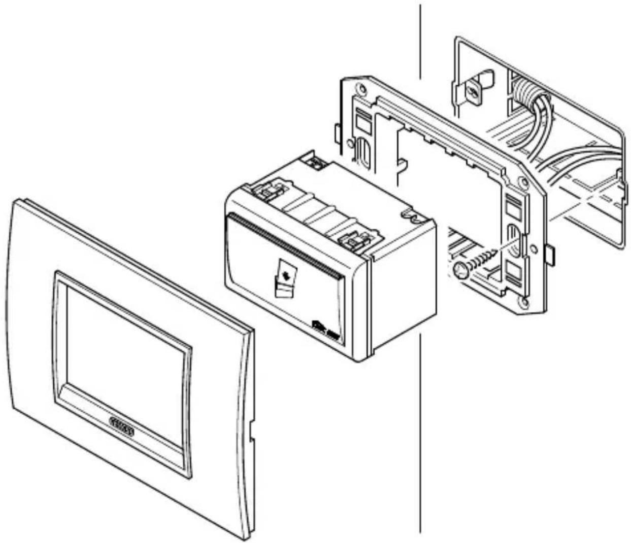
Assembly and connections
Only mount the reader in a horizontal position.
natural_image
Exploded view diagram of an electronic device showing internal components and casing (no text or labels)General description
To start up the device you must access the "KNX / EIB Button" to switch from normal mode to programming mode; the button is on the back of the casing.
When installing the device, make sure that the connection cables are long enough to extract the device / support frame from the flush-mounted box together.
Connection of the bus cable to the KNX / EIB clamp
The Bus KNX / EIB clamp (supplied with the device) is suitable for a single wire conductor with a 0.6-0.8 mm.
Connection of the transponder reader to the bus line
Insert the KNX / EIB Bus clamp, previously connected to the bus cable, into the integrated bus coupling slot which is on the back of the device.
Slide the bus clamp as far as possible.
Configuration
The transponder reader must be configured using one of the access management softwares - "GWHotel" or "GWAccess" used to configure the transponder badges and the assigning of access rights
INSTALLATION
Electrical safety
Pollution level (according to IEC 60664-1 Standard): 2.
Protection rating (according to EN 60529 Standard): IP 20.
Protection class (according to IEC 61140): III.
Overload rating (according to IEC 664-1): III.
Bus: safety voltage SELV DC 24V.
Complies with EN 50090 and IEC 664-1 Standards.
EMC requirements
Complies with EN 61000-6-3, EN 61000-6-1 and EN 50090-2-2 Standards.
Conditions of use
According to EN 50090-2-2 Standards.
Ambient temperature while working: 0°C +45°C.
Storage temperature: - 20 + 55°C.
Relative humidity: max. 90%.
Homologation
KNX/EIB homologated.
EC Marking
Complies to the low voltage EC Directive (civil and industrial building).
TECHNICAL SPECIFICATIONS
Power supply
BUS voltage KNX/EIB: 29V dc SELV
BUS absorption: 5mA
External auxiliary voltage: 12/24V ac/dc +/- 10%
Max. auxiliary power absorption: 150mA
KNX/EIB Inputs
3 contacts without potential
the power is supplied internally at 24V 1mA
Relay outputs
2 NO contacts 2A cosφ0,6, 24V ac
Channel 1: general use or electrical lock command
Channel 2: courtesy lights or general use
Transponder reader
Chip reader/writer transponder Atmel/Temic
Power supplied internally at 5V dc
Working power frequency: 125KHz
Control elements
Button to switch between normal mode / programming mode
Indicators
Backlit badge slot reader
FRANÇAIS
Porte-Transponder
Attention - Important
Bornes Bus KNX / EIB:
natural_image
Technical line drawing of an electrical enclosure with internal components and wiring (no text or symbols)Tension BUS KNX / EIB: 29V cc SELV
natural_image
Line drawing of a rectangular device with a card symbol and 'KNX E13' label, no readable text or symbols beyond the logo.natural_image
Exploded view diagram of an electronic device showing internal components and casing (no text or labels)Descripción general
natural_image
Exploded view diagram of an electronic device showing internal components and casing (no text or labels)


- Morsetti Bus KNX / EIB:
- Attention - Important
- CONTENTS
- OPERATING INSTRUCTIONS page
- INSTALLATION
- TECHNICAL SPECIFICATIONS ......23
- OPERATING INSTRUCTIONS
- Description of the product and how it works
- Front view
- Connections
- Screw terminals:
- KNX / EIB Bus terminals:
- KNX/ EIB Button
- KNX / EIB Led
- Warnings for installation phase
- Assembly and connections
- General description
- Connection of the bus cable to the KNX / EIB clamp
- Connection of the transponder reader to the bus line
- Configuration
- Electrical safety
- EMC requirements
- Conditions of use
- Homologation
- EC Marking
- TECHNICAL SPECIFICATIONS
- Power supply
- KNX/EIB Inputs
- Relay outputs
- Transponder reader
- Control elements
- Indicators
- FRANÇAIS
- Porte-Transponder
- Bornes Bus KNX / EIB:
- Descripción general
Brand : Gewiss
Model : GW14682
Category : Security System