SP2 - Pump Fluval - Free user manual and instructions
Find the device manual for free SP2 Fluval in PDF.
| Product type | Aquarium pump |
| Brand | Fluval |
| Model | SP2 |
| Maximum flow rate | 3600 L/h |
| Maximum head height | 1.95 m (230-240 V) / 1.9 m (120 V) |
| Power | 55 W (230-240 V) / 58 W (120 V) |
| Power supply | 230-240 V ~ 50/60 Hz or 120 V ~ 60 Hz |
| Inlet and outlet diameter | 1 inch (25.4 mm) |
| Usage | Submersible or external, for indoor aquarium |
| Maximum water temperature | 35 °C |
| Shaft material | High-quality ceramic |
| Maintenance | Check flow rate weekly; clean impeller assembly at least once a year |
| Cleaning | Clean water only, non-abrasive brush; do not use detergents |
| Safety | Disconnect before any intervention; form a drip loop; never run dry |
| Spare parts | Available (base, motor, impeller cover, impeller assembly, threaded fittings, seals) |
| Warranty | 3 years against defects in materials and workmanship |
| Country of origin (estimated) | Canada / France (depending on distribution) |
Frequently Asked Questions - SP2 Fluval
User questions about SP2 Fluval
0 question about this device. Answer the ones you know or ask your own.
Ask a new question about this device
Download the instructions for your Pump in PDF format for free! Find your manual SP2 - Fluval and take your electronic device back in hand. On this page are published all the documents necessary for the use of your device. SP2 by Fluval.
USER MANUAL SP2 Fluval
natural_image
Close-up of a mechanical pump assembly with threaded ports and housing, set against a blurred background (no visible text or symbols)IMPORTANT SAFETY INSTRUCTIONS
WARNING - To guard against injury, basic safety precautions should be observed, including the following:
READ AND FOLLOW ALL SAFETY INSTRUCTIONS
and all important notices on the appliance before using. Failure to do so may result in loss of fish life and/or damage to this appliance.
- DANGER – To avoid possible electric shock, special care should be taken since water is employed in the use of aquarium equipment. For each of the following situations, do not attempt repairs yourself; return the appliance to an authorized service facility for service or discard the appliance.
A. If the appliance shows any sign of abnormal water leakage or if RCD (or GFCI- Ground Fault Current Interrupter) switches off disconnect the power supply cord from main power supply and remove the aquarium pump from water.
B. Carefully examine the appliance after installation. It should not be plugged if there is water on parts not intended to be wet.
C. Do not operate any appliance if it has a damaged cord or plug, or if it is malfunctioning or it is dropped or damaged in any
manner. The power cord of this appliance cannot be replaced; if the cord is damaged, the appliance should be discarded. Never cut the cord.
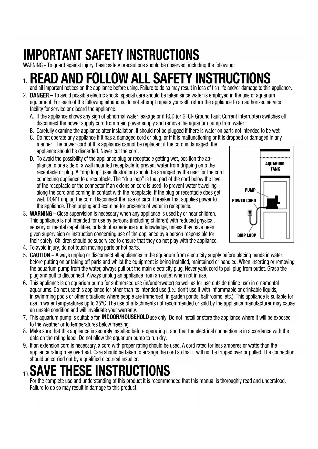
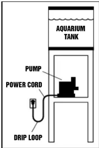
D. To avoid the possibility of the appliance plug or receptacle getting wet, position the appliance to one side of a wall mounted receptacle to prevent water from dripping onto the receptacle or plug. A "drip loop" (see illustration) should be arranged by the user for the cord connecting appliance to a receptacle. The "drip loop" is that part of the cord below the level of the receptacle or the connector if an extension cord is used, to prevent water travelling along the cord and coming in contact with the receptacle. If the plug or receptacle does get wet, DON'T unplug the cord. Disconnect the fuse or circuit breaker that supplies power to the appliance. Then unplug and examine for presence of water in receptacle.
-
WARNING – Close supervision is necessary when any appliance is used by or near children. This appliance is not intended for use by persons (including children) with reduced physical, sensory or mental capabilities, or lack of experience and knowledge, unless they have been given supervision or instruction concerning use of the appliance by a person responsible for their safety. Children should be supervised to ensure that they do not play with the appliance.
-
To avoid injury, do not touch moving parts or hot parts.
- CAUTION – Always unplug or disconnect all appliances in the aquarium from electricity supply before placing hands in water, before putting on or taking off parts and whilst the equipment is being installed, maintained or handled. When inserting or removing the aquarium pump from the water, always pull out the main electricity plug. Never yank cord to pull plug from outlet. Grasp the plug and pull to disconnect. Always unplug an appliance from an outlet when not in use.
- This appliance is an aquarium pump for submersed use (in/underwater) as well as for use outside (inline use) in ornamental aquariums. Do not use this appliance for other than its intended use (i.e.: don't use it with inflammable or drinkable liquids, in swimming pools or other situations where people are immersed, in garden ponds, bathrooms, etc.). This appliance is suitable for use in water temperatures up to 35°C. The use of attachments not recommended or sold by the appliance manufacturer may cause an unsafe condition and will invalidate your warranty.
- This aquarium pump is suitable for INDOOR/HOUSEHOLD use only. Do not install or store the appliance where it will be exposed to the weather or to temperatures below freezing.
- Make sure that this appliance is securely installed before operating it and that the electrical connection is in accordance with the data on the rating label. Do not allow the aquarium pump to run dry.
- If an extension cord is necessary, a cord with proper rating should be used. A cord rated for less amperes or watts than the appliance rating may overheat. Care should be taken to arrange the cord so that it will not be tripped over or pulled. The connection should be carried out by a qualified electrical installer.
SAVE THESE INSTRUCTIONS
For the complete use and understanding of this product it is recommended that this manual is thoroughly read and understood. Failure to do so may result in damage to this product.
The Fluval Sea Aquarium Pump is designed to be used immersed in a sump tank as well as outside water, connected with proper tubing to a tank. The pump is designed to treat clean water only; use an adequate pre-filter to avoid large particles from entering the pump.
WARNING: Always unplug or disconnect all appliances in the aquarium and sump tank from the electrical supply before installing, repairing, maintaining or handling the equipment in the water. IMPORTANT: To achieve the best pump operation, always use the largest bore hose possible. Avoid sharp bends in the hosing; gradual curves are preferred.
Fluval Sea Aquarium Pump Performances
| Q max [l/h] | H max [m] | Q at 1.4m [l/h] P [W] | PUMP INPUT | PUMP OUTPUT | ||||||
| Pump Model | 230-240 V | 120 V | 230-240 V | 120 V | 230-240 V | 120 V | 230-240 V | 120 V | ||
| Fluval Sea SP2 (14335) | 3600 | 3600 | 1.95 | 1.9 | 1200 | 1100 | 55 | 58 | 1” | 1” |
| Fluval Sea SP4 (14337) | 7500 | 6900 | 3.6 | 3.6 | 5900 | 5100 | 90 | 88 | 1” | 1” |
| Fluval Sea SP6 (14339) | 12300 | 13000 | 3.7 | 4 | 8300 | 9000 | 100 | 135 | 1/4” | 1/4” |
INSTALLATION
The aquarium pump should always be placed on a firm base using its proper mounting base with rubber feet.
WARNING: Do not plug in the pump before it is correctly and fully installed.
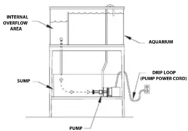
a) Submersed inside a sump tank: Choose the correct position for the pump, to avoid bending of the tubes as much as possible. Screw the threaded fitting onto the pump intake nozzle and connect an appropriate hose. The use of flexible hosing instead of rigid pipes is recommended to reduce vibration transmissions.
IMPORTANT: To reach the best pump performances be sure the water level in the sump tank is proper and adequate. This avoids the pump from sucking in air and creating a water vortex. If needed, a 90° threaded elbow fitting (not included) can be installed on the pump intake. NOTE: The 90° elbow has to be installed facing downwards.
b) Outside a tank (in-line): The pump should be primed first before plugging it in. Use appropriate fittings to connect the pump to the tank by means of a pipe or a hose. The use of a ball valve, fitted to both the inlet and the outlet pipe will be of help when servicing the pump to disconnect it from the system. When connecting the pump, the use of flexible hosing is suggested to reduce vibration transmissions.
Pump operation: Once the pump is fully installed, insert the plug into the electrical receptacle/socket to start.
TYPICAL INSTALLATIONS
text_image
INTERNAL OVERFLOW AREA AQUARIUM DRIP LOOP (PUMP POWER CORD) SUMP PUMP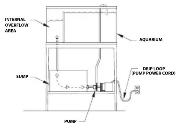
text_image
INTERNAL OVERFLOW AREA AQUARIUM DRIP LOOP (PUMP POWER CORD) SUMP PUMPMAINTENANCE
WARNING: Always unplug or disconnect all appliances in the aquarium from the electrical supply before installing, repairing, maintaining or handling the equipment in the water. NEVER LIFT THE PUMP BY THE CORD.
To avoid shortening the life of the pump, follow these simple maintenance procedures:
- Once a week, verify that the pump performance is satisfactory. If you detect a drop in pump performance (such as a decrease in water flow from the pump to the aquarium) the pump should be cleaned (impeller, impeller well, and impeller cover) to restore the water flow to its original performance level (see Cleaning).
- When necessary, or at least once a year, clean the pump motor completely (impeller, impeller well, and impeller cover) and check that no limestone deposits, which could jeopardize pump operation, are present.
- To keep the pump in good working order, always replace any worn parts.
- Check the hosing integrity regularly and especially after maintenance to ensure there are no kinks in the hosing that would impede pump performance.
- The pump motor has no user serviceable parts. If the motor or the electrical cord is damaged, discard the pump.
CLEANING
CAUTION: The pump motor includes a high quality ceramic shaft that provides long-lasting, reliable performance when properly maintained. However, extreme care should be taken when handling the shaft during maintenance. Avoid dropping or pressing too hard on it to avoid breakage or hairline fractures, which may cause the shaft to snap while in operation.
WARNING: Always unplug or disconnect all appliances in the aquarium from the electrical supply before installing, repairing, maintaining or handling the equipment in the water.
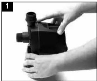
Model SP2
- Remove the pump from the aquarium tank or in-line setup; remove the pump base.
- Using a Phillips screwdriver (cross-headed screwdriver), unscrew the screws and remove the impeller cover from the pump motor.
- Grasp the rotor and pull gently to remove the impeller assembly (with magnetic ceramic shaft).
- Remove the rotor and the rubber damper (between the impeller and the rotor) to be able to clean impeller.
- Remove the seal ring and O-ring
- Clean all components in clean water only, using a small, nonabrasive brush, if necessary. DO NOT USE DETERGENTS OR OTHER CHEMICAL CLEANERS which could damage the pump and pollute the aquarium.
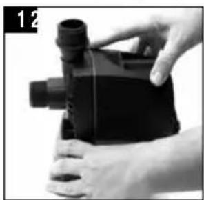
- Reassemble all components with care in reverse order. Ensure that the impeller bearing, bushing and Rubber Support are correctly placed at the bottom of the impeller well. Ensure that the rubber damper (between the impeller and rotor) is replaced correctly.
- Before replacing the pump back in the tank or set-up, rinse the threaded fittings in clean water to remove any residual dirt or debris.
natural_image
Close-up of hands holding a black industrial pump component (no visible text or symbols)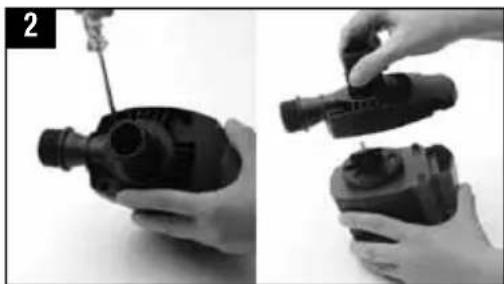
natural_image
Two-step black-and-white photo showing a hand adjusting a mechanical component, no text or symbols visible
natural_image
Two-step black-and-white photo showing hands assembling a mechanical component (no text or symbols visible)
natural_image
Two mechanical components with arrows indicating assembly or transformation (no visible text or symbols)
natural_image
Two black-and-white photos showing a hand holding a small mechanical component, one with a ring and the other with a circular ring (no text or symbols visible)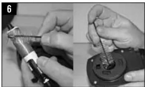
natural_image
Close-up of hands using a tool to adjust or install a mechanical component (no visible text or symbols)Model SP4/SP6
- Remove the pump from the aquarium tank or in-line setup; remove the pump base.
- Using a Phillips screwdriver (cross-headed screwdriver), unscrew the screws and remove the impeller cover from the pump motor.
- Using a flathead screwdriver, carefully lift out the impeller assembly (with magnetic ceramic shaft). Please refer to screwdriver symbol on top of impeller assembly to know where to apply screwdriver.
- Remove O-ring.
- Clean all components in clean water only, using a small, nonabrasive brush, if necessary. DO NOT USE DETERGENTS OR OTHER CHEMICAL CLEANERS which could damage the pump and pollute the aquarium.
- Reassemble all components with care in reverse order. Ensure that the impeller bearing, bushing and Rubber Support are correctly placed at the bottom of the impeller well.
- Before replacing the pump back in the tank or set-up, rinse the threaded fittings in clean water to remove any residual dirt or debris.
natural_image
Close-up of hands holding a black plastic device with a cylindrical port, no visible text or symbols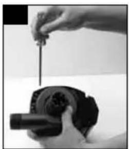
natural_image
Close-up of a hand holding a small mechanical component with a cylindrical shaft (no visible text or symbols)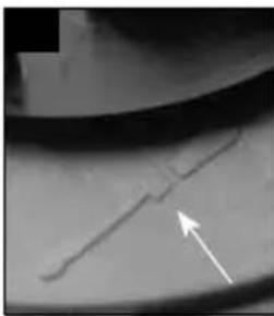
natural_image
Close-up of a mechanical component with a white arrow pointing to a specific feature (no visible text or symbols)
natural_image
Close-up of hands using a screwdriver to adjust internal components (no visible text or symbols)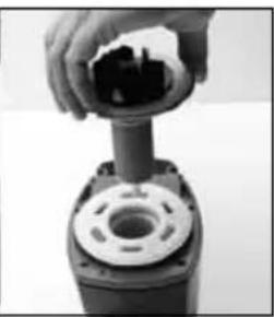
natural_image
Close-up of a hand inserting a component into a mechanical housing (no visible text or symbols)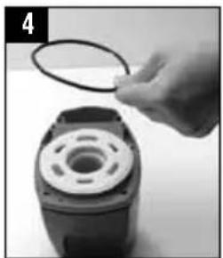
natural_image
Close-up of a hand holding a circular wire attached to a mechanical component (no visible text or symbols)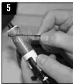
natural_image
Close-up of a hand holding a small object with a tool, possibly a tool or device (no visible text or symbols)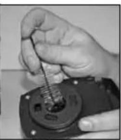
natural_image
Close-up of a hand using a screwdriver to adjust a small electronic component (no visible text or symbols)THREADED FITTINGS
a) The threaded fittings have to be hand tightened until they fully fit on input / output pump threaded connections.
b) During maintenance operation check that the pump's Input and Output threaded connections are free from dirt, debris and/or any obstructions to avoid problems during the threaded fittings installation. Clean the pump's Input and Output threaded connections by rinsing them in tap water.
c) To avoid damaging the pump's threaded connections, the pump itself must be always be stable and securely installed on a flat and levelled surface.
d) Using a Phillips (cross-headed) screwdriver, tighten the screws until they fully fit. Afterwards tighten an additional quarter turn the screws.
CAUTION
a) The threaded fittings should easily assemble/disassemble. If you feel you are applying excessive force in order to fit the threaded fitting coupling to the pump's corresponding threaded connections, then do not continue the installation as the threaded connections could be damaged. Proceed by removing the threaded fittings and cleaning both the connections and the fittings in tap water.
b) Extreme care should be considered when using accessories not included with the pump. Do not use tooling for tightening connection accessories as the force produced can damage the pump threaded connections.
c) Do not use glues or sealants for fixing on the pump's threaded fitting or different connection accessories not included with the pump first sale configuration.
d) Before installing the threaded fittings, it is recommended, as a good and common practice, wrapping the input / output pump threaded connections with some Teflon.
PUMP BASE
a) Pump must always be stable and fixed. It has to be secured installed on a flat and levelled surface.
b) In case of difficulty removing the pump from its base, check that the pump based is free from dirt. Just in case clean the pump and the pump base in tap water.
TROUBLESHOOTING TIPS
LOW FLOW FROM PUMP
- Check the hose for blockages.
- Check that the pump is free of dirt and debris.
NO FLOW FROM PUMP
- Check that the power supply is on.
- Check that the plug is correctly connected to the electrical receptacle/socket.
- Check the hose for blockages.
- Check that the pump is free from dirt, debris and/or any obstructions.
- Check that the Impeller Assembly is free from dirt, debris and/or any obstructions. If the Impeller Assembly is damaged it must be replaced with the appropriate spare part.
REPLACING THE BUSHING AND O-RING / BUSHING AND RUBBER SUPPORT
Though the bushing is made of very resistant material, it is prone to wearing in certain conditions. For this reason, it is recommended that you replace it whenever the impeller unit is replaced. Follow the instructions provided with the replacement parts package. Once you have replaced the Bushing and O-Ring (Fluval Sea Aquarium Pump SP4, SP6) or Bushing and Rubber Support (Fluval Sea Aquarium Pump SP2), reassemble all parts with care.
REPLACEMENT PARTS TABLE
| DESCRIPTION FLUVAL SEA SP2 FLUVAL SEA SP4 FLUVAL SEA SP6 | |||
| (Art. #) (Art. #) (Art. #) | |||
| Pump Base A20334 A20334 A20334 | |||
| Pump Motor A20310 A20312 A20314 | |||
| Impeller Cover A20322 A20324 A20326 | |||
| Impeller Assembly A20316 A20318 A20320 | |||
| Threaded Fitting & Gasket (2 pcs) | A20330 (1” / 25.4mm) | A20330 (1” / 25.4mm) | A20332 (1 1/4” / 32mm) |
| Seal Ring PT762 | PT764 | PT764 | |
| Impeller Well Cover | PT768 | n/a | n/a |
WARRANTY
Fluval Sea Aquarium Pumps are guaranteed against defects in material or workmanship under normal aquarium usage and service for 3 years. We offer a 3 year guarantee on all non replaceable parts which means that the pump will be repaired or replaced at the manufacturer's discretion, free of charge, when the complete pump is returned with proof of purchase and postage paid. This warranty does apply to any pump that has been subjected to misuse, negligence or tampering. No liability is assumed with respect to loss or damage to livestock or personal property irrespective of the cause thereof.
FOR AUTHORIZED GUARANTEE REPAIR SERVICE:
For Authorized Warranty Service please return (well packaged and by registered post) to the address below enclosing dated receipt and reason for return. If you have any queries or comments about the operation of this product, please let us try to help you before you return the product to your retailer. Most queries can be handled promptly with a phone call. When you call (or write), please have all relevant information such as model number, age of product, details of aquarium set-up, as well as the nature of the problem.
CANADA: Consumer Repair, Rolf C. Hagen Inc, 20500 Trans Canada Hwy, Baie d'Urfé QC H9X 0A2
U.S.A.: Rolf C. Hagen (U.S.A.) Corp., 305 Forbes Blvd, Mansfield, MA. 02048
UK: Rolf C. Hagen (UK) Ltd, Customer Service Department California Drive, Whitwood Ind Est., Castleford West Yorkshire WF10 5QH www.hagen-uk.custhelp.com
CALL US ON OUR TOLL-FREE NUMBER:
Canada only: 1-800-554-2436 between 9:00 a.m. and 4:30 p.m. Eastern Standard Time. Ask for Customer Service.
U.S. only: 1-800-724-2436 between 9:00 a.m. and 4:00 p.m. Eastern Standard Time. Ask for Customer Service.
U.K. only: Helpline Number 01977 556622. Between 9:00 AM and 5:00 PM, Monday to Friday (excluding Bank Holidays).
RECYCLING: This symbol bears the selective sorting symbol for waste electrical and electronic equipment (WEEE). This means that this product must be handled pursuant to European Directive 2002/96/EC in order to be recycled or dismantled to minimize its impact on the environment. Check with your local Environmental Agency for possible disposal instructions or take to an official council registered refuse collection point. Electronic products not included in the selective sorting process are potentially dangerous for the environment and human health due to the presence of hazardous substances.

MESURES DE SÉCURITÉ IMPORTANTES
natural_image
Close-up of hands holding a black plastic pump bottle with a cylindrical port (no visible text or symbols)
natural_image
Two-step black-and-white photo showing a hand adjusting a mechanical component, no visible text or symbols
natural_image
Two-step black-and-white photo showing hands assembling a camera module, no text or symbols visible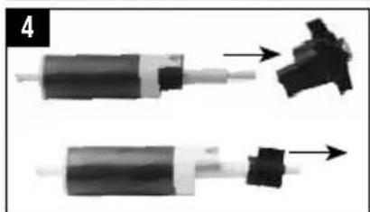
natural_image
Two mechanical components with arrows indicating assembly or transformation (no visible text or symbols)
natural_image
Two black-and-white photos showing a hand holding a circular component, one open and the other closed (no text or symbols visible)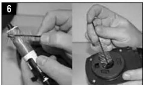
natural_image
Close-up of hands using a tool to adjust or install a mechanical component (no visible text or symbols)natural_image
Close-up of hands holding a black mechanical device with a cylindrical port (no visible text or symbols)
natural_image
Two-step black-and-white photo showing a hand adjusting a mechanical component, no visible text or symbols
natural_image
Two-step black-and-white photo showing hands assembling a mechanical component, no visible text or symbols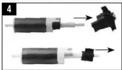
natural_image
Two mechanical components with arrows indicating assembly or transformation (no visible text or symbols)
natural_image
Two black-and-white photos showing a hand holding a circular component, one open and the other closed, both with no visible text or symbols.
natural_image
Close-up of hands using a tool to adjust or install a mechanical component (no visible text or symbols)Modelo SP4/SP6
natural_image
Close-up of hands holding a black plastic pump bottle with a cylindrical port (no visible text or symbols)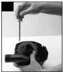
natural_image
Close-up of hands using a tool to adjust or install a mechanical component (no visible text or symbols)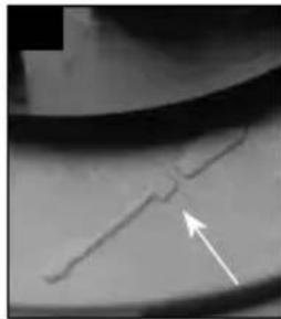
natural_image
Close-up of a curved metallic surface with a white arrow pointing to a specific feature (no text or symbols visible)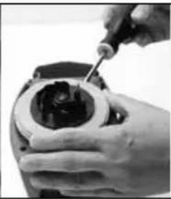
natural_image
Close-up of a hand using a screwdriver to adjust or install a mechanical component (no visible text or symbols)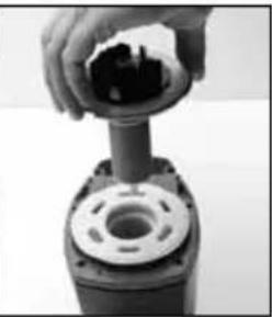
natural_image
Close-up of hands holding a mechanical component with a cylindrical housing (no visible text or symbols)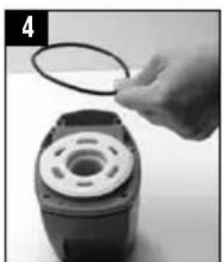
natural_image
Hand holding a circular component attached to a mechanical housing (no visible text or symbols)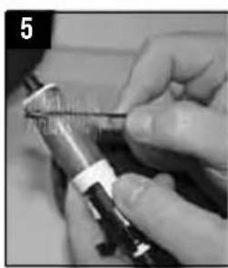
natural_image
Close-up of hands using a tool to apply material or equipment (no visible text or symbols)
natural_image
Close-up of a hand using a pipette to apply liquid into a small electronic device (no visible text or symbols)ACCESORIOS ROSCADOS
natural_image
Close-up of hands holding a black plastic device with a cylindrical port (no visible text or symbols)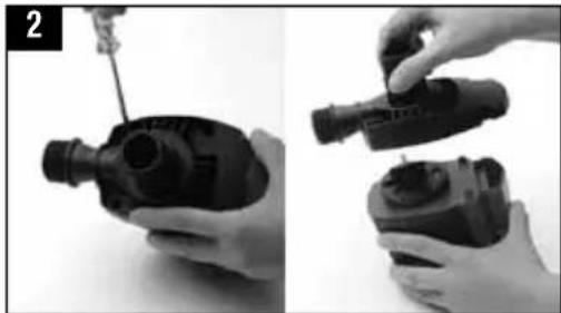
natural_image
Two black-and-white photos showing a hand holding a mechanical component, with no visible text or symbols.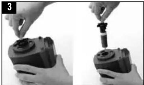
natural_image
Two-step black-and-white photo showing hands assembling a mechanical component, no visible text or symbols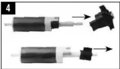
natural_image
Two mechanical components with arrows indicating assembly or movement, no visible text or symbols
natural_image
Two black-and-white photos showing a hand holding a small mechanical component, one with a circular ring and the other with a grid-like structure (no text or symbols visible)
natural_image
Close-up of hands using a tool to adjust or install a mechanical component (no visible text or symbols)Modell SP4/SP6
natural_image
Close-up of hands holding a black mechanical device with a cylindrical component (no visible text or symbols)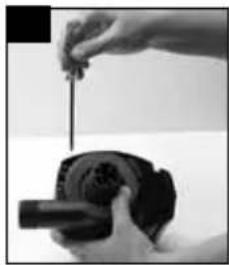
natural_image
Close-up of a hand holding a small mechanical component with a tool, no visible text or symbols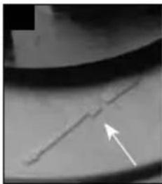
natural_image
Close-up of a metallic surface with a diagonal line and an arrow pointing to it (no text or symbols visible)
natural_image
Close-up of a hand using a screwdriver to adjust internal components (no visible text or symbols)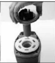
natural_image
Close-up of hands assembling a mechanical component (no visible text or symbols)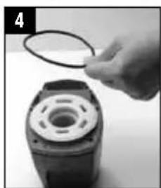
natural_image
Close-up of a hand holding a circular ring attached to a mechanical component (no visible text or symbols)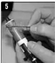
natural_image
Close-up of hands holding a small mechanical component (no visible text or symbols)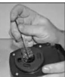
natural_image
Close-up of a hand using a tool to apply liquid into a small electronic device (no visible text or symbols)VERSCHRAUBUNGEN
natural_image
Close-up of hands holding a black mechanical device with a cylindrical port (no visible text or symbols)
natural_image
Two-step black-and-white photo showing a hand adjusting a mechanical component, no visible text or symbols
natural_image
Two-step black-and-white photo showing hands assembling a mechanical component (no text or symbols visible)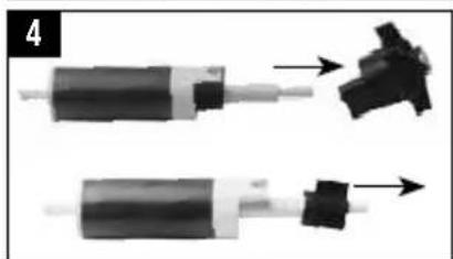
natural_image
Two mechanical components with arrows indicating assembly or transformation (no visible text or symbols)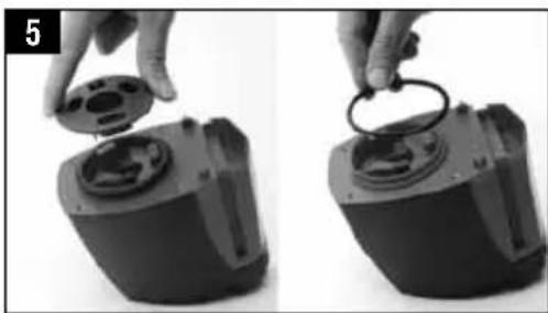
natural_image
Two black-and-white photos showing a hand holding a circular component, one open and the other closed (no text or symbols visible)
natural_image
Close-up of hands using a tool to adjust or install a mechanical component (no visible text or symbols)20500 Trans Canada Hwy, Baie D'Urfé QC H9X 0A2
UK: Rolf C. Hagen (UK) Ltd, Customer Service Department,
California Drive, Whitwood Ind Est., Castleford, West Yorkshire WF10 5QH
natural_image
Close-up of hands assembling a black mechanical component (no visible text or symbols)
natural_image
Two-step black-and-white photo showing a hand adjusting a mechanical component, no text or symbols visible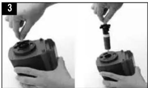
natural_image
Two-step black-and-white photo showing hands assembling a camera module, no text or symbols visible
natural_image
Two mechanical components with arrows indicating assembly or transformation (no visible text or symbols)
natural_image
Two black-and-white photos showing a hand holding a circular component, one with a ring and the other with a ring (no text or symbols visible)
natural_image
Close-up of hands using a tool to adjust or install a mechanical component, no visible text or symbolsnatural_image
Close-up of hands holding a black industrial pump device with a cylindrical component (no visible text or symbols)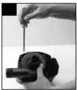
natural_image
Close-up of a hand holding a small mechanical component with a cylindrical shaft (no visible text or symbols)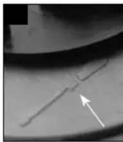
natural_image
Close-up of a metallic surface with a diagonal line and an arrow pointing to it (no text or symbols visible)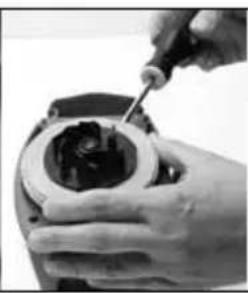
natural_image
Close-up of hands using a screwdriver to adjust internal components (no visible text or symbols)
natural_image
Close-up of a hand pressing a mechanical component with a circular base (no visible text or symbols)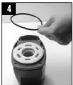
natural_image
Hand holding a circular wire attached to a mechanical component (no visible text or symbols)
natural_image
Close-up of hands using a tool to apply material or equipment (no visible text or symbols)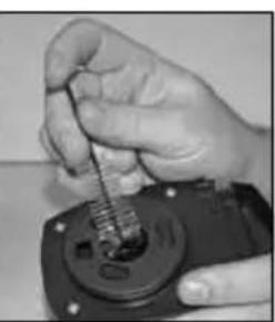
natural_image
Close-up of hands using a tool to adjust or install a mechanical component (no visible text or symbols)DRAADFITTINGS
Fluval and Hagen are registered trademarks of Rolf C. Hagen Inc.
Ver: 31/12-INT