
PIN116 - Multimeter Profile - Free user manual and instructions
Find the device manual for free PIN116 Profile in PDF.
| Product Type | Digital Multimeter |
| Brand | Profile |
| Model | PIN116 |
| Display | LCD 2000 counts |
| Overvoltage Category | CAT II |
| Power Supply | 9V Battery (type 6F22) |
| Automatic Shutdown | After 15 minutes of inactivity |
| Measurement Functions | DC/AC voltage, DC current, resistance, continuity, diode test, temperature |
| DC Voltage Ranges | 200mV, 2000mV, 20V, 200V, 600V |
| AC Voltage Ranges | 200V, 600V |
| DC Current Ranges | 2000µA, 20mA, 200mA, 10A |
| Resistance Ranges | 200Ω, 2000Ω, 20kΩ, 200kΩ, 2000kΩ |
| Temperature Range | -20°C to +760°C / -4°F to 1400°F |
| Diode Test | Max current 1mA, open circuit voltage 2.8V DC |
| Audible Continuity | Threshold < 30Ω |
| Protection | Fuse 10A/250V (10A range) |
| Low Battery Indicator | BAT symbol |
| Backlight | Activated by button, automatic shutdown after 10 seconds |
| HOLD Function | Freeze the displayed value |
| Safety | Do not measure on live circuits, respect polarities, discharge capacitors |
| Maintenance | Clean with a dry cloth, replace battery and fuses as per instructions |
| Repairability | Fuse replaceable, battery replaceable |
Frequently Asked Questions - PIN116 Profile
User questions about PIN116 Profile
0 question about this device. Answer the ones you know or ask your own.
Ask a new question about this device
Download the instructions for your Multimeter in PDF format for free! Find your manual PIN116 - Profile and take your electronic device back in hand. On this page are published all the documents necessary for the use of your device. PIN116 by Profile.
USER MANUAL PIN116 Profile
DIGITALE MULTIMETER MEDIUM MULTIMETRE DIGITAL MEDIUM
PIN-116

AC Wisselstroom of - spanning
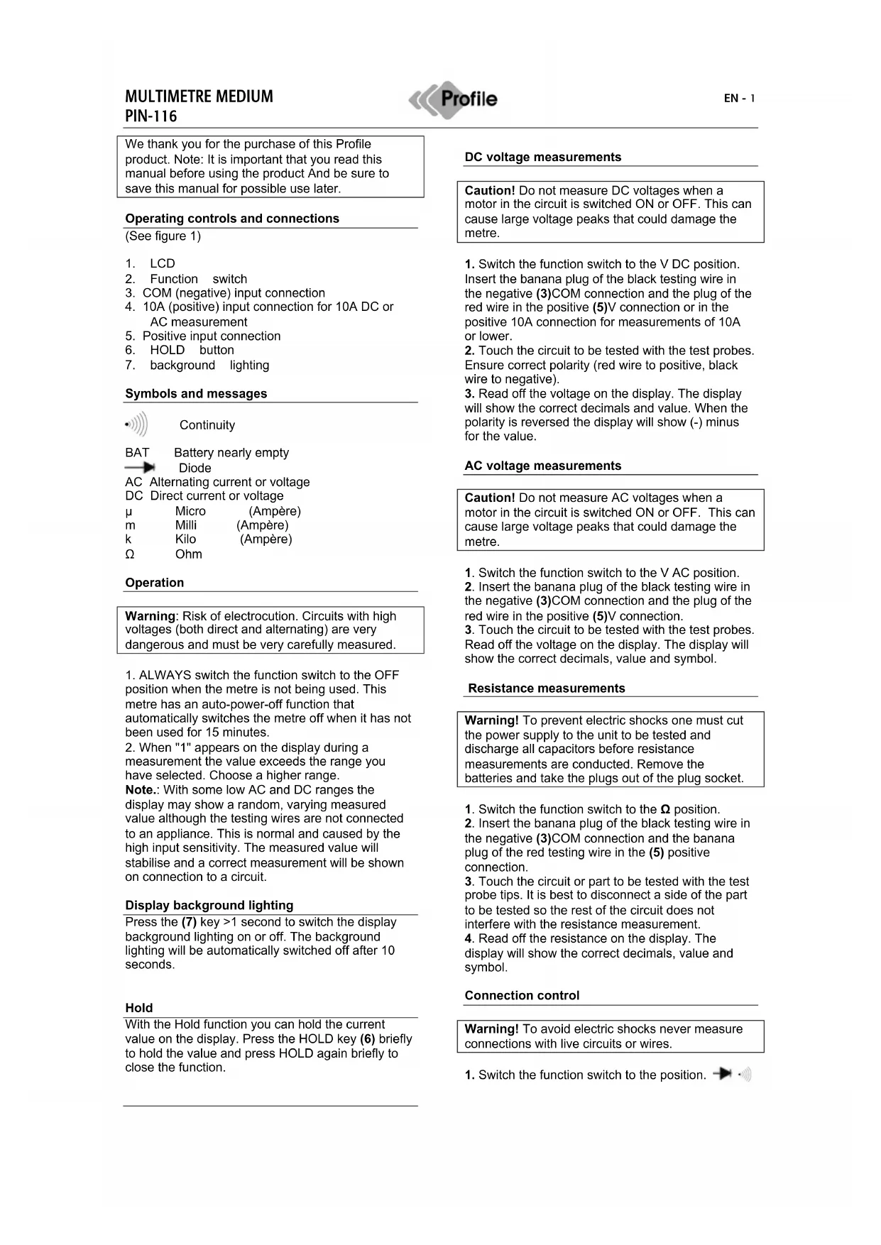
We thank you for the purchase of this Profile product. Note: It is important that you read this manual before using the product And be sure to save this manual for possible use later.
Operating controls and connections
(See figure 1)
- LCD
- Function switch
3.COM (negative) input connection - 10A (positive) input connection for 10A DC or AC measurement
- Positive input connection
- HOLD button
- background lighting
Symbols and messages

Continuity

Battery nearly empty
Diode
AC Alternating current or voltage
DC Direct current or voltage
μ
Micro
(Ampère)
m
Milli
(Ampère)
K
Kilo
(Ampère)
Ω
Ohm
Operation
Warning: Risk of electrocution. Circuits with high voltages (both direct and alternating) are very dangerous and must be very carefully measured.
-
ALWAYS switch the function switch to the OFF position when the metre is not being used. This metre has an auto-power-off function that automatically switches the metre off when it has not been used for 15 minutes.
-
When "1" appears on the display during a measurement the value exceeds the range you have selected. Choose a higher range.
Note.: With some low AC and DC ranges the display may show a random, varying measured value although the testing wires are not connected to an appliance. This is normal and caused by the high input sensitivity. The measured value will stabilise and a correct measurement will be shown on connection to a circuit.
Display background lighting
Press the (7) key >1 second to switch the display background lighting on or off. The background lighting will be automatically switched off after 10 seconds.
Hold
With the Hold function you can hold the current value on the display. Press the HOLD key (6) briefly to hold the value and press HOLD again briefly to close the function.
DC voltage measurements
Caution! Do not measure DC voltages when a motor in the circuit is switched ON or OFF. This can cause large voltage peaks that could damage the metre.
- Switch the function switch to the V DC position. Insert the banana plug of the black testing wire in the negative (3)COM connection and the plug of the red wire in the positive (5)V connection or in the positive 10A connection for measurements of 10A or lower.
- Touch the circuit to be tested with the test probes. Ensure correct polarity (red wire to positive, black wire to negative).
- Read off the voltage on the display. The display will show the correct decimals and value. When the polarity is reversed the display will show (-) minus for the value.
AC voltage measurements
Caution! Do not measure AC voltages when a motor in the circuit is switched ON or OFF. This can cause large voltage peaks that could damage the metre.
- Switch the function switch to the V AC position.
- Insert the banana plug of the black testing wire in the negative (3)COM connection and the plug of the red wire in the positive (5)V connection.
- Touch the circuit to be tested with the test probes. Read off the voltage on the display. The display will show the correct decimals, value and symbol.
Resistance measurements
Warning! To prevent electric shocks one must cut the power supply to the unit to be tested and discharge all capacitors before resistance measurements are conducted. Remove the batteries and take the plugs out of the plug socket.
- Switch the function switch to the position.
- Insert the banana plug of the black testing wire in the negative (3)COM connection and the banana plug of the red testing wire in the (5) positive connection.
- Touch the circuit or part to be tested with the test probe tips. It is best to disconnect a side of the part to be tested so the rest of the circuit does not interfere with the resistance measurement.
- Read off the resistance on the display. The display will show the correct decimals, value and symbol.
Connection control
Warning! To avoid electric shocks never measure connections with live circuits or wires.
- Switch the function switch to the position.

- Insert the banana plug of the black testing wire in the negative (3)COM connection and the banana plug of the red testing wire in the positive + (5) connection () .
- Touch the circuit or wire you want to check with the test probe tips.
- If the resistance is lower than approx. 100 an acoustic signal is sounded. The display will also show the actual resistance.
Diode test
Warning! To avoid electric shocks do not test live diodes.
1.Insert the banana plug of the black measuring cable in the negative (3) (COM) input, and the banana plug of the red measuring cable in the positive diode input (5).
-
Set the switch to
-
Place the measuring heads on the diode to be tested. The conductor voltage is 400 to 700mV . The reverse voltage is shown by "1". Short-circuit appliances give a result close to 0mV . An open appliance is shown by "1" for both poles.
Measurements of AC/DC current intensity
Warning! To prevent electric shocks you may not measure AC current intensities in circuits with a voltage of over 250V AC.
Caution! Do not conduct current measurements in the 10A range that last longer than 30 seconds. If they last longer than 30 seconds this can cause damage to the metre and/or testing wires.
- Insert the banana plug of the black testing wire in the negative(1)COM connection.
- For power measurements up to 200mA DC, set the function switch to the highest DC mA position, and insert the banana plug of the red measuring cable in the (mA) input.
- For power strengths of 10 A DC, set the function switch to 10A, and insert the banana plug of the red measuring cable in the 10A input.
- Switch the voltage of the circuit to be tested off and open the circuit at the point where you want to measure the current intensity.
- Touch the negative side of the circuit with the black test probe. Touch the positive side of the circuit with the red test probe.
- Put power on the circuit.
- Read off the current intensity on the display. The display will show the correct decimals, value and symbol.
Temperature measurements
Warning! To prevent electric shocks you must disconnect both test probes from any power sources before you measure the temperature.
- If you want to measure the temperature in (F)arenheit, switch the function switch to the ^ F position. If you want to measure the temperature in
(C)elcius, switch the function switch to the ^ C position.
2. Insert the banana plug of the thermocouple probe in the negative (3) COM connection and the plug of the red wire in the positive (5) Temp diode connection.
3. Touch the part you want to measure the temperature of with the end of the temperature probe. Hold the probe against the part to be tested until the measured value stabilises (approx. 30 seconds).
4. Read off the temperature on the display. The digital measured value will show the correct decimals and value.
Warning! To prevent electric shocks check that the thermocouple has been removed before you proceed with another measuring operation.
Replacing the battery
Warning! To prevent electric shocks you must disconnect the testing wires from any power sources before you open the cover of the battery compartment.
- When the batteries are nearly empty the message "BAT" appears on the right of the display. The battery must then be replaced.
- Follow the instructions for replacing batteries. See the paragraph on changing the battery in this manual.
- Dispose of old batteries at a collection point.
Warning! To prevent electric shocks you may not use the metre until the cover of the battery compartment has been replaced and fastened.
Placing batteries
- Disconnect the metre's testing wires.
- Remove the rubber housing
- Open the battery cover by removing the screw with a screwdriver.
- Place the battery in the compartment. Ensure the correct polarity.
- Replace the battery cover. Fasten using the two screws.
Note.: If your metre is not functioning properly you must check the fusing and the battery to make sure they are still in working order and correctly fitted.
Replacing the fusing
Warning! To prevent electric shocks you must disconnect the testing wires from any power sources before you open the cover of the fuse compartment.
- Disconnect the testing wires from the metre and all items to be tested.
- Remove the rubber housing
- Open the fusing compartment cover by removing the screw in the cover.
- Remove the old fusing from the compartment by carefully pulling it out.
- Place the new fusing in the holder.
- Always use fusing of the correct size and specification (10A/250V fast-reacting for the 10A range).
- Replace the fusing cover. Insert the screw and tighten firmly.
Warning! To prevent electric shocks you may not use the metre until the cover of the fuse compartment has been replaced and fastened.
Specifications
Overvoltage category: CATII
Display: 2,000 counts
Polarity: Automatic, (-) indication negative polarity.
Various Graphics
DC voltage
| Range Resolution | Accuracy | |
| 200mV | 0.1mV | +/- 0,5% van rdg +/- 2- figures |
| 2000mV | 1mV | |
| 20V | 0.01mV | +/- 0,8% van rdg +/- 2- figures |
| 200V | 0.1mV | |
| 600V 1V +/- 1% van rdg | +/- 2- figures | |
AC voltage
| Range Resolution | Accuracy | |
| 200V 0.1V +/- 1,2% van rdg | +/- 10- figures | |
| 600V | 1V | 50/60Hz |
Direct current
| Range Resolution | Accuracy | |
| 2000 μ | 1 μA | +/- 1% van rdg |
| 20mA | 10 μA | +/- 2- figures |
| 200mA | 100 μA | +/- 1.2% van rdg |
| +/- 2- figures | ||
| 10A 10mA +/- 3.0% van rdg | +/- 2- figures | |
Resistance
| Range Resolution | Accuracy | |
| 200 Ω | 0.1 Ω | +/- 0.8% van rdg +/- 2- figures |
| 2000 Ω | 1 Ω | |
| 20k Ω | 0.01k Ω | |
| 200k Ω | 0.1 k Ω | |
| 2000k Ω | 1 k Ω | +/-1.2% van rdg +/- 2- figures |
Temperature
| Range Resolution | |
| -20°C ~+760°C | 1°C |
| -4°F ~1400°F | 1°F |
Diodetest
Test current
Max 1mA
Open circuit voltage: 2.8 V DC typical