
220 - Walkie-talkie MIDLAND - Free user manual and instructions
Find the device manual for free 220 MIDLAND in PDF.
| Product type | Multi-standard CB walkie-talkie |
| Brand | Midland |
| Model | 220 |
| Dimensions (W x H x D) | 170 x 32 x 170 mm |
| Weight | 1.020 kg |
| Power supply | 12.6 V DC ± 10% (direct battery wiring or fuse box) |
| Frequency range | 25.615 to 30.105 MHz |
| Number of channels | Up to 80 FM (depending on band) |
| Transmit power | 4 W AM/FM (depending on band) |
| Receiver | Dual conversion superheterodyne |
| Display | Multifunction backlit with color change (white, yellow, purple, red, light blue, green, blue or off) |
| Anti-noise system | ESP2 (Electronic Parasite Suppression 2) |
| Main functions | Band selection, channel memory (M1/M4), emergency channel (CH9/19), AM/FM mode, adjustable microphone and RF gain, squelch, volume |
| Speaker | Front for DIN installation |
| Microphone | With UP/DOWN and PTT buttons, 6-pin connector |
| Connectors | Antenna (SO239), external speaker, external S-meter, power |
| Installation | Car stereo DIN slot, metal bracket supplied, antenna with good ground |
| Safety | Reverse polarity protection, never transmit without antenna, use a bipolar switch on the power supply |
| Maintenance and cleaning | Clean with a soft dry cloth. Avoid solvents. Check connections regularly. |
Frequently Asked Questions - 220 MIDLAND
User questions about 220 MIDLAND
0 question about this device. Answer the ones you know or ask your own.
Ask a new question about this device
Download the instructions for your Walkie-talkie in PDF format for free! Find your manual 220 - MIDLAND and take your electronic device back in hand. On this page are published all the documents necessary for the use of your device. 220 by MIDLAND.
USER MANUAL 220 MIDLAND
6. Manopola "ON/OFF-VOLUME":
Frequency band selection 13
Frequency band chart 14
TECHNICAL SPECIFICATIONS 15
Midland 220 is the brand new Multi Standard CB transceiver, essential in its functionalities but with advanced performances, such as the ESP2 (noise killing device).
Midland 220 is a very practical radio, very easy to install even into the DIN housing of the vehicles (usually suitable for car radios).
As required by this kind of installation the speaker is on the front panel to guarantee a high-quality acoustic level.
MIDLAND 220 is supplied with a microphone with UP/DOWN buttons, mounting bracket and adaptor for DIN mounting.
FUNCTIONS AND LOCATION OF THE CONTROLS
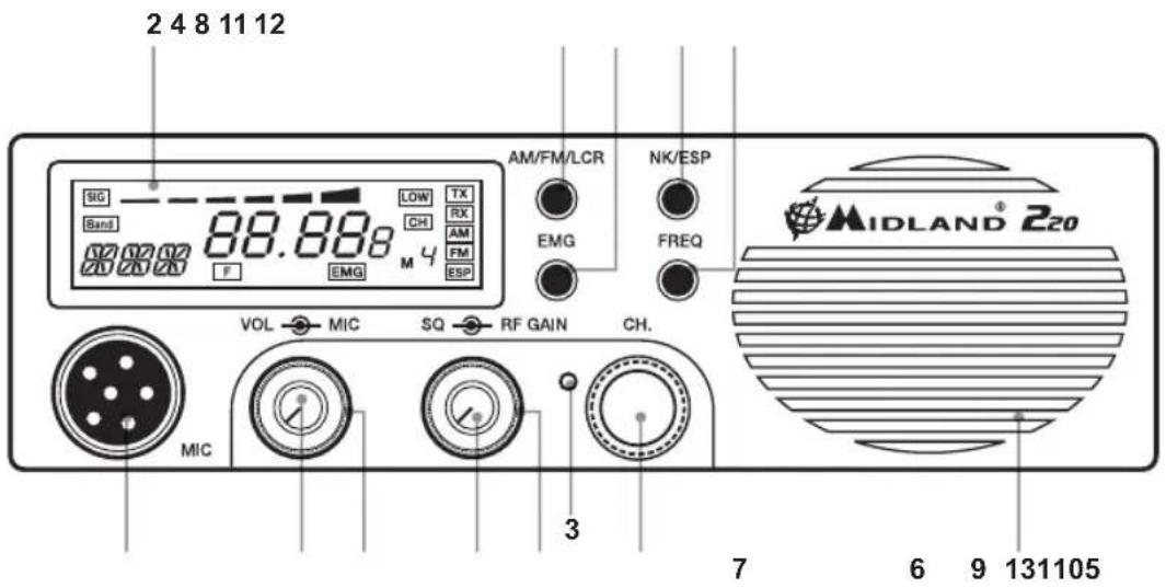
- Channel selector: it permits the manual channel selection.
- Multifunction back-lighted display. It shows:
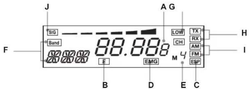
A) Selected channel (from 1 up 40) or operative frequency
B) FREQ button activated
C) ESP: reducing noise device activated
D) EMG: indicates channel being used or when the emergency channels are activated
E) M1-M4: memory channel indicator
F) Indicates the frequency band selected
G) Appears when the radio transmits in low power (this condition happens only in some frequency bands - see the chart at the end of the manual)
H) RX/TX: reception (RX) / transmission (TX) indicator.
1) AM/FM mode.
J) Received signal strength and transmitted signal power.
-
Button for changing colour: by pushing a pointed object into the hole, you can change the backlight colour of the display. You can choose amongst the following colours: white, yellow, violet, red, light blue, green, blue or no colour.
-
"AM/FM"(LCR) button: To select AM or FM mode. If you select a frequency band operating in FM mode only, this button enables the LCR function (Last Channel Recall).
-
"Squelch" Control: For the maximum receiver sensitivity, the control must be regulated exactly where the receiver background noise disappears.
-
"ON/OFF Volume" Control. In "OFF" position your transceiver is OFF. "VOLUME" position: by turning this knob, you set the audio level.
- Microphone jack: Insert the mic connector into this jack.
- EMG button: Emergency channel. By pressing it, the unit will be automatically positioned on CH 9/19 (emergency channels). The display will show "EMG". It will not be possible to accidentally change the channel.
- "Mic (Microphone) Gain Control": in TX mode, it controls the microphone amplification.
The best results are obtained by getting the best modulation: use the mike by trying to find the optimal amplification level and distance from your mouth.
- "RF" (Radio Frequency) Gain Control: it controls the reception sensitivity. To increase the sensitivity, simply turn it clockwise. Sensitivity decreases turning it counterclockwise. Low sensitivity is useful in case of very strong signals.
11. "N.K./ESP" button
Pressing this switch, you activate the noise killing device. Receiver noise and interference can now be largely eliminated by the ESP2 system.
12. FREQ button
With this button, you can:
- visualize the operative frequency (if you keep pressing the button for 3 seconds approx.), or the channel in use;
- activate the second functions of the "M" (M1/M4) buttons.
M1/M4:
MIDLAND 220 has the possibility to store and to recall, when necessary, 2 channels previously memorized.
To memorize one channel, follow the procedure herebelow:
A) Select the channel with the appropriate selector or the "UP/DN" buttons on the microphone;
B) Push the "FREQ" button: the display will show "F";
C) Keep pressed the "AM/FM/LCR" button for 3 seconds: you will hear a "BIP" and the display will show "M1".
To memorize the other channels, repeat these steps and press "EMG".
To recall a channel previously stored, push the "FREQ" switch and then "AM/FM/LCR" (M4) or "EMG" (M1).
13. Front speaker
REAR PANEL
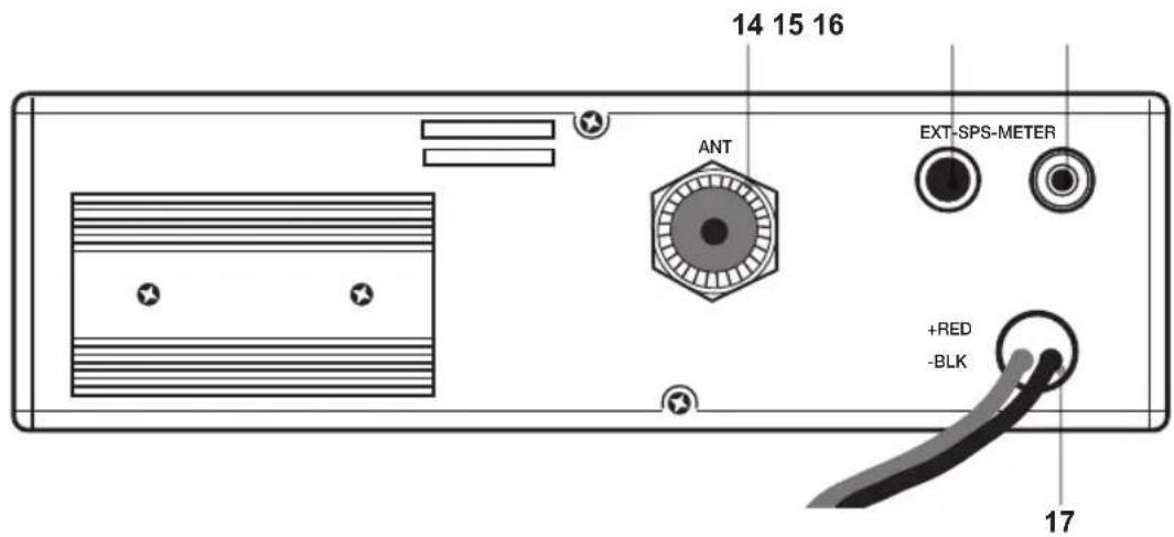
- Antenna connector (SO239 connector type)
- "EXT" jack: external loudspeaker jack.(the internal loudspeaker is excluded)
- S.Meter jack: it allows an external "S. Meter" connection
- Power 12.6V DC: power supply cable
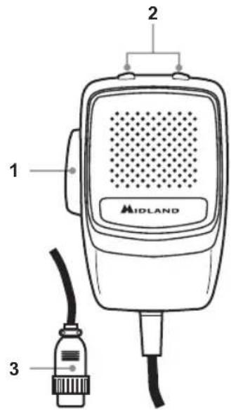
MICROPHONE
- PTT: transmission button
- UP/DOWN buttons: manual channel selector.
- 6 pin microphone connector
INSTALLATION
Safety and convenience are the primary considerations for mounting any piece of mobile equipment.
All controls must be readily available to the operator without interfering with the movements necessary for safe operation of the vehicle. Interference from the connecting cables may contribute to the loss of control of the vehicle.
Set the proper position in the car to install the transceiver using the supplied supporting bracket or eventually the DIN mounting bracket.
Tighten the retaining screws. The mounting bracket must be close to metallic parts.
POWER SUPPLY
Be sure the transceiver is OFF. In the direct-voltage power supply, it is very important to observe the polarity even if the unit is protected against the accidental inversion:
Red = positive pole (+)
Black = negative pole (-)
The same colours are present on the battery and in the fuse box of the car. Correctly connect the cable terminal to the battery.
INSTALLING AN ANTENNA
- Place the antenna as high as possible
- The longer the antenna is, the better will be the performance
- If possible, mount the antenna in the centre of whatever surface you choose
- Keep antenna cable away from noise sources, such as the ignition switch, gauges,etc.
- Make sure you have a solid metal-to-metal ground connection.
- Prevent cable damage during antenna installation.
WARNING: To avoid damage, never operate your CB radio without connecting a proper antenna.
A periodical control of the cable and of the S.W.R. is recommended.
HOW TO OPERATE YOUR TRANSCEIVER
- Screw the microphone plug into the microphone jack.
- Make sure your antenna is connected to the antenna connector.
- Make sure the SQUELCH control is turned fully counterclockwise.
- Turn on the unit and adjust the volume control.
- Select your desired channel.
- To transmit, press the PTT button and speak in a normal tone of voice.
- To receive, release the PTT button.
The frequency bands must be chosen according to the country where you are going to operate.
Procedure:
- Switch off the unit.
- Turn it on while pushing the "N.K./ESP" button.
- Select the desired frequency band by pushing the UP / DOWN buttons (see the chart here below).
Wait for 5 seconds or switch off and then on the radio.
NOTE1: In the UKE or UKC frequency bands, you can select directly the other band by pushing the
"AM/FM/LCR" button for 3 seconds.
NOTE2: If you select a frequency band which operates in FM mode only, the "AM/FM/LCR" control enables the LCR function (last channel recall).
| Digits displayed | Country Band Frequency | |
| I Italy | 40CH AM/FM 4W Fx 26,965-27,405 MHz | |
| I2 Italy | 34CH AM/FM 4W Fx 26,875-27,265 MHz | |
| D Germany | 80CH FM 4W 12CH AM 1W Fx 26,565-27,405 MHz | |
| D2 Germany | 40CH FM 4W 12CH AM 1W Fx 26,965-27,405 MHz | |
| D3 Germany | 80CH FM 4W 40CH AM 1W Fx 26,565-27,405 MHz | |
| EU Europe | 40CH FM 4W 40CH AM 1W Fx 26,965-27,405 MHz | |
| EC Europe | 40CH FM 4W Fx 26,965-27,405 MHz | |
| E Spain | 40CH AM/FM 4W Fx 26,965-27,405 MHz | |
| F | France | 40CH FM 4W 40CH AM 1W |
| UKE | England | 40CH FM 4W |
| UKC | England | 40 CH FM 4W CEPT |
| PL Poland | 40CH AM/FM 4W Fx 26,960 - 27,400MHz |
ATTENTION!
The frequency band allowed all over Europe is 40 CH FM 4W (EC).
TECHNICAL SPECIFICATIONS
GENERAL
Channels .40 FM (see the frequency band chart)
Frequency Range 25.615 to 30.105 MHz
Frequency Control PLL
Operating Temperature Range 10°/+55°C
DC input voltage 12.6V DC ±10%
Duty cycle 5/5/90 (1 hour of use)
Size 170 (L)x 52 (H)x 170 (D) mm
Weight 1,020 kg
RECEIVER
Receiving system .dual conversion superheterodyne
Intermediate frequency . 1^ IF: 10.695 MHz · II° IF: 455 KHz
Sensitivity 1uV for 20 dB SINAD
Audio output power @10% THD ..>4.0W @ 8 Ohm (external speaker)
2.0W @ 8 Ohm (internal speaker)
Audio distortion . less than 3 % @ 1 KHz
Current drain at stand/by 200mA
TRANSMITTER
Output power. 4W @ 12.6V DC
Modulation.. AM: from 85% to 95%
FM: 1,8 KHz ± 0,2 KHz
Current drain. 1100mA (Power position with no modulation)
All specifications are subject to change without notice.
A readily accessible disconnect device shall be incorporated in the installation wiring. The disconnect device shall disconnect both poles simultaneously.

INHALT
BEDIENELEMENTE 18
INSTALLATION 21
Stromversorgung 21
With this button, you can:
Modulation AM: from 85% to 95%
FM: 1,8 KHz ± 0,2 KHz
Current drain 1100mA (Power position with no modulation)
Tropofoia (DC 12.6V DC ±10%
Kukao etoupyia 5/5/90 (1 wpa etoupyia)
△aστασεις 170 (M)x 52 (Y) x 1170 (Π) mm
Bapoc 1,020 kg
AEKTH
Ioxuc Edoou (RF) .4W @ 12.6Vdc
△iαóppωση AM: 85% - 95%
FM: 1,8 KHz ± 0,2 KHz
Katavalwon peuatoC 1100mA (xwiic diapopwoan)
OLeC oI pOdiaypaqec duvatai va aAalaouov xwpi cTPOeIoToinOn.
Evac ukoa Tpoaaoioc biakottns Ta pTei va ouvdeei oTo Kaawio Eykaataoans, o toioe aTouc duo nolouc tauroxpova.

SPIS TRESCI
FUNKCJE I UMIEJSCOWIENIE KONTROLEK 58
INSTALACJA 61
Zasilanie 61

- Manopola "ON/OFF-VOLUME":
- TECHNICAL SPECIFICATIONS 15
- FUNCTIONS AND LOCATION OF THE CONTROLS
- "N.K./ESP" button
- FREQ button
- M1/M4:
- Front speaker
- REAR PANEL
- MICROPHONE
- INSTALLATION
- POWER SUPPLY
- INSTALLING AN ANTENNA
- HOW TO OPERATE YOUR TRANSCEIVER
- ATTENTION!
- TECHNICAL SPECIFICATIONS
- GENERAL
- RECEIVER
- TRANSMITTER
- INHALT
- BEDIENELEMENTE 18
- INSTALLATION 21
- AEKTH
- SPIS TRESCI
- FUNKCJE I UMIEJSCOWIENIE KONTROLEK 58
Brand : MIDLAND
Model : 220
Category : Walkie-talkie