
278 DS - Walkie-talkie MIDLAND - Free user manual and instructions
Find the device manual for free 278 DS MIDLAND in PDF.
| Product Type | CB Walkie-Talkie |
| Brand | MIDLAND |
| Model | 278 DS |
| Dimensions | 180 × 35 × 140 mm |
| Weight | 0.850 kg |
| Supply Voltage | 12.6 V DC ±10% |
| Max Consumption | 2,500 mA |
| Frequency Range | 26.565 – 27.99125 MHz |
| Number of Channels | 40 channels |
| Reception System | Double conversion superheterodyne |
| Sensitivity | 0.5 µV for 20 dB SINAD (AM and FM) |
| Audio Bandwidth | 300 Hz – 3 kHz |
| Antenna Impedance | 50 ohms |
| Transmit Power | 4 W FM (depending on band) |
| Duty Cycle | TX 5% – RX 5% – Standby 90% (over 1 h) |
| Operating Temperature | 10 °C to +55 °C |
| Main Functions | Digital automatic squelch, Noise Blanker, SCAN scanning, EMG emergency channel, frequency band selection, microphone key lock |
| Display | Multifunction display (channel, level, mode, etc.) |
| Antenna Connector | SO239 (for PL259) |
| Fuse | F 5 A 250 V |
| Warranty | 24 months (device), 6 months (accessories) |
| Maintenance and Cleaning | Clean with a soft dry cloth. Avoid solvents. |
Frequently Asked Questions - 278 DS MIDLAND
User questions about 278 DS MIDLAND
0 question about this device. Answer the ones you know or ask your own.
Ask a new question about this device
Download the instructions for your Walkie-talkie in PDF format for free! Find your manual 278 DS - MIDLAND and take your electronic device back in hand. On this page are published all the documents necessary for the use of your device. 278 DS by MIDLAND.
USER MANUAL 278 DS MIDLAND
Function and location of the controls Pag.2
Installation
Pag.4
Power supply Pag. 4
Installing an antenna Pag. 4
How to operate with your transceiver. Pag. 5
Frequency band selection Pag. 5
Frequency band chart Pag. 5
Warranty Pag. 6
Technical specifications Pag. 7
Your MIDLAND 278 DS represents the state-of-the art in high-tech engineering. Designed for the Citizen Band Mobile operation, this compact package is big in performance. It is a quality piece of electronic equipment, skillfully constructed with the finest components. The circuitry is all a solid-state, mounted on rugged printed circuit boards. It is designed for many years of reliable, trouble-free performance. Your mobile CB has a built Phase-Locked Loop synthesizer circuit.
The PLL circuit achieves a new technique for generating all the required frequencies with fewer crystals. The result is much tighter frequency control and superior reliability.
MIDLAND 278 DS is equipped with the "NOISE BLANKER" (noise reducer device) that reduces considerably the audio noises up to 95% , allowing a clear communication even when the signal is disturbed.
The brand new feature of MIDLAND 278 DS is the Digital Automatic Squelch, very useful because there's no need to turn manually the squelch knob every time. The automatic squelch allows a very clear reception of all the incoming signals and eliminates the unwanted background noise.
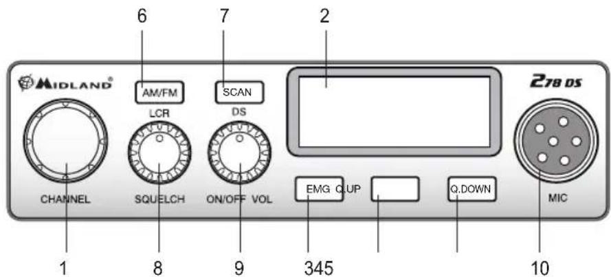
FUNCTION AND LOCATION OF THE CONTROLS
-
Channel selector
-
Multifunction backlighted display. It shows:
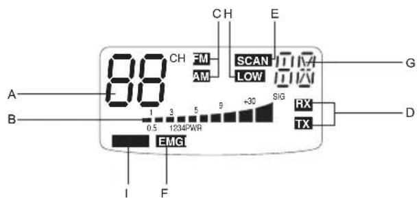
A. Channel selected number
B. The received signal strength and the power of the transmitting signal
C. AM/FM mode
D. RX/TX:TX=transmit mode; RX=receive mode
E. SCAN mode
F. EMG mode
G. Frequency band selected or digital automatic squelch selected (AS)
H. LOW: displayed when the radio transmits in low power (this mode is possible with some frequency bands only - see the Frequency band chart).
I. LOCK: microphone (UP/DOWN buttons) lock enabled.
- "EMG" button: Emergency channel. By pressing it, you will be automatically positioned on CH 9 (emergency channel). The display will show "EMG". It will not be possible to change accidentally the channel.
4.5. "Q.UP/Q.DOWN" buttons: To skip 10 channels UP (Q. UP) or 10 channels DOWN (Q.DOWN).
- "AM/FM"(LCR) button: To select AM or FM mode. If you switch on the unit and push "AM/FM"(LCR) and "SCAN" at the same time, you will select the operating band, which will be visualised on the display.
If you select a frequency band operating in FM mode only, this button enables the LCR function (Last Channel Recall).
- "SCAN (DS)" button: With this control, you can automatically seek for a busy channel. Turn the Squelch clockwise until the background noise is no longer heard.
Press the "SCAN" button: the transceiver will scan automatically all the channels. If you switch on the unit and push "SCAN" and "AM/FM"(LCR) at the same time, you will select the operating band, which will be visualised on the display.
DS (Digital Automatic Squelch): differently from the standard squelch, the D.S. automatically detects the squelch level that allows a clear reception of all incoming signals, there's no need to make any further adjustment. This function also eliminates the unwanted background noise in absence of incoming signals.
To select the automatic squelch:
- Turn on the radio.
-
Press briefly the SCAN (DS) button. As confirmation of your selection, the display shows AS in the top right corner, in place of the frequency band in use.
-
"Squelch" Control: For the maximum receiver sensitivity, the control must be regulated exactly where the receiver background noise disappears.
- "ON/OFF Volume" Control. In "OFF" position your transceiver is OFF. Turn this control clockwise to switch on the unit. Turn the knob clockwise a little more to set the audio level, until you get a comfortable reception.
- Microphone jack: Insert the mic connector into this jack.
REAR PANEL
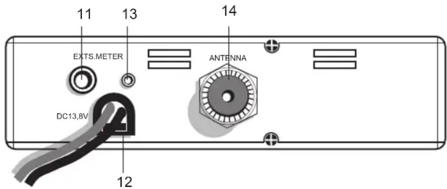
- "EXT" jack: external loudspeaker jack.(the internal loudspeaker is excluded)
- Power 12.6V DC: power supply cable
- S.Meter jack: it allows an external "S. Meter" connection
- Antenna connector (SO239 connector type)
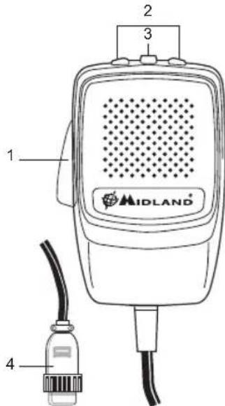
MICROPHONE
- PTT: transmission button
- UP/DOWN buttons: manual channels selector
- LOCK button: it allows you to lock the UP/DOWN buttons.
- 6 pin microphone connector
INSTALLATION
Safety and convenience are the primary consideration for mounting any piece of mobile equipment. All controls must readily available to the operator without interfering with the movements necessary for safe operation of the vehicle. Set the proper position in the car to install the transceiver using the supplied supporting bracket or eventually the slide bracket. Tighten the retaining screws. The fixing bracket must be close to metallic parts.
POWER SUPPLY
Be sure the transceiver is OFF. In the direct-voltage power supply, is very important to observe the polarity even if the unit is protected against the accidental inversion:
Red = positive pole (+)
Black = negative pole (-)
The same colors are present on the battery and in the fuse box of the car. Correctly connect the cable terminal to the battery.
ATTENTION
To obtain best performances we recommend to install the radio in a place with enough air circulation.
INSTALLING AN ANTENNA
- Place the antenna as high as possible
- The longer is the antenna, the better will be the performance
- If possible, mount the antenna in the center of whatever surface you choose
- Keep antenna cable away from noise sources, such as the ignition switch, gauges,etc.
- Make sure you have a solid metal-to-metal ground connection.
- Prevent cable damage during antenna installation.
WARNING: To avoid damage, never operate your CB radio without connecting a proper antenna. A periodical control of the cable and of the S.W.R. is recommended.
REPLACING FUSE
If you replace the fuse for DC power Cord, use F 5A 250V type. The parameters and the symbol of the fuse are indicated in the following label.

HOW TO OPERATE WITH YOUR TRANSCEIVER
- Screw the microphone plug into the microphone jack.
- Make sure your antenna is securely connected to the antenna connector.
- Make sure the SQUELCH control is turned fully counterclockwise.
- Turn on the unit and adjust the volume control.
- Select your desired channel.
- To transmit, press the PTT button and speak in a normal tone of voice.
- To receive, release the PTT button.
The frequency bands must be chosen according to the country where you are going to operate.
Procedure:
- Switch off the unit.
- Turn it on while pushing the "AM/FM" e "SCAN" buttons at the same time.
- Rotate the "CHANNEL" knob and select the desired frequency band (see the chart here below).
- To stop your selection, press the "AM/FM" button.
NOTE1: In the UK frequency band, you can select directly the EC band by pushing the “AM/FM” button for 2 seconds.
NOTE2: If you select a frequency band which operates in FM mode only, the "AM/FM" control enables the LCR function (last channel recall).
| Digits displayed Country | |
| I Italy 40 CH AM/FM 4Watt | |
| I2 Italy 34 CH AM/FM 4Watt | |
| D Germany | 80 CH FM 4Watt / 12 CH AM 1Watt |
| D2 Germany | 40 CH FM 4Watt / 12 CH AM 1Watt |
| D3 Germany | 80 CH FM 4Watt / 40 CH AM 1Watt |
| D4 Germany | 80 CH FM 4Watt / 40 CH AM 4Watt |
| EU Europe | 40 CH FM 4Watt / 40 CH AM 1Watt |
| EC 40 CH FM 4Watt | |
| E Spain 40 CH AM/FM 4Watt | |
| F France 40 CH FM 4Watt / 40 CH AM 1Watt | |
| PL Poland 40 CH AM/FM 4Watt | |
| UK | England 40 CH FM 4 Watt English frequencies + EC 40 CH FM 4Watt |
ATTENTION!
The frequency band definitely allowed all over Europe is 40 CH FM 4W (EC).
WARRANTY
This product is covered by European warranty rulings and should be returned to the place where purchased for repair or replacement if not repairable.
In the event it that it is returned to us by your supplier then we will either repair or replace within 15 working days from receipt. During the Warranty period, the Manufacturer or the authorized customers service will, in accordance with this Limited Warranty, remedy defects by repair or replace the product.
This Limited Warranty is only valid and enforceable in the country where the user has purchased the product.
The warranty period lasts 2 years and starts at the time of product's original purchase by the first end-user.
In the event of a product defect, please return it to the authorized customer service or to the Manufacturer himself.
To make use of this warranty, it is necessary to return to the authorized service centre:
The affected product (or accessory)
The original proof of purchase, which clearly indicates the name and address of the seller and the date and place of purchase.
The warranty does not cover normal wear and tear of the product, defects or damage caused to the Product by misuse with, or connection to, any product, accessory software and/or services not produced or supplied by the manufacturer or by use of the product for any other use than for intended use of the product.
The warranty is not enforceable if the product has been opened, modified or repaired by anyone other than the authorized service centre; if it is repaired using unauthorized spare parts or if the serial number has been removed, erased, defaced, altered or is illegible.
The warranty is not enforceable if the product has been exposed to moisture, to dampness or to extreme thermal or environmental conditions or to corrosion, to oxidation, to spillage of food or liquid or to influence from chemical products.
TECHNICAL SPECIFICATIONS
GENERAL
Channels (see the frequency band chart)
Frequency Range 26.565-27.99125 MHz
Duty cycle (% on 1 hour) TX 5% - RX 5% - Stand-by 90%
Frequency Control 20
Operating Temperature Range. -10^ / + 55^ C
DC input voltage 12.6V DC ±10%
Size. 180 (L) x35 (H) x140 (P) mm
Weight 0,850 kg
RECEIVER
Receiving system .dual conversion superheterodyne
Intermediate frequency . 1^ IF: 10.695 MHz · II° IF: 455 KHz
Sensitivity. 0.5 V for 20 dB SINAD in FM mode 0.5 V for 20 dB SINAD in AM mode
Audio output power @10% THD .2.0 W @ 8 Ohm
Audio distortion.. less than 8 % @ 1 KHz
Image rejection 65 dB
Adjacent channel rejection 65 dB
Signal/Noise ratio 45 dB
Current drain at stand/by 250mA
TRANSMITTER
Output power 4W max
Modulation. AM: from 85% to 95%
FM:1,8 KHz ± 0,2 KHz
Frequency response. 300 Hz/3 KHz
Output impedance RF 50 Ohm unbalanced
Signal/Noise Ratio 40 dB MIN
Current drain. max 2500mA
INHALT
Einführung . 1
REEMPLACEMENT DU FUSIBLE
Puissance audio. 2 W @ 8 Ohms
Distorsion. Mieux que 8 % @ 1 Khz
Réjection image 65 dB
Réjection canal adjacent 65dB
Consommation 250 mA
EMETTEUR
Puisance 4 W max
Modulation FM 1,8 KHz ± 0,2 KHz

Brand : MIDLAND
Model : 278 DS
Category : Walkie-talkie