
248XL - Walkie-talkie MIDLAND - Free user manual and instructions
Find the device manual for free 248XL MIDLAND in PDF.

| Product type | CB walkie-talkie (transceiver) |
| Brand | Midland |
| Model | 248XL |
| Dimensions (L x H x D) | 150 x 45 x 175 mm |
| Weight | 1 kg |
| Power supply | 12.6 VDC ±10% |
| Standby current consumption | 450 mA |
| Transmission current consumption | 2500 mA max |
| RF output power | 4 W max |
| Frequency range | 26.565 - 27.99125 MHz |
| Modulation types | AM and FM |
| Number of channels | Up to 80 (depending on band) |
| Display | Backlit multifunction display |
| Key features | ESP2, Noise Blanker, Analog S-Meter, Dual Watch, Scan, LCR, LOCK |
| Microphone | With PTT and UP/DOWN keys |
| Antenna connector | SO-239 |
| External speaker jack | Yes (EXT jack) |
| Protection | Against reverse polarity |
| Operating temperature | -10°C to +55°C |
| Certifications | Directive 99/05/EC |
| Replacement fuse | F 5A 250V |
Frequently Asked Questions - 248XL MIDLAND
User questions about 248XL MIDLAND
0 question about this device. Answer the ones you know or ask your own.
Ask a new question about this device
Download the instructions for your Walkie-talkie in PDF format for free! Find your manual 248XL - MIDLAND and take your electronic device back in hand. On this page are published all the documents necessary for the use of your device. 248XL by MIDLAND.
USER MANUAL 248XL MIDLAND
Italy - Restrictions on the use - According to the Italian Frequency Allocation Table, issued on the G.U. No. 169 - Supplement 146 - of 20th July 2002 - note 49G, the standard ■ in AM modulation needs a radiating system with a gain not higher than -6dB, such as, for example, with the antenna "PC8" with original cable.
Function and location of the controls....3
Installation....7
Power supply 7
Installing an antenna 7
How to use your Midland 248XL....8
Frequency band selection....8
Frequency band chart 8
Specifications....9
Midland 248XL is a mobile transceiver whose main feature is the possibility to select any of the European CB bands with an easy and quick operation.
Midland 248XL is equipped with the "ESP2" and "NOISE BLANKER" (noise reducer devices) that reduce considerably the audio noises up to 95% , allowing a clear communication even when the signal is disturbed.
The wide multifunctional backlit display shows the number of the channel in use or the correspondent frequency even in conditions of deep darkness.
Midland 248XL is also equipped with an analogical S-Meter, showing the transmitted power and the signal received.
The unit is preset at the factory on the "EC" band, 40CH FM 4W.
FUNCTION AND LOCATION OF THE CONTROLS
FRONT PANEL
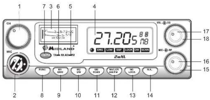
- Channel selector: it permits the manual channel selection.
- Microphone jack: insert the mic connector into this jack.
- Indicator: this meter indicates the receiving signal strength and the transmitter RF output power.
- Multifunction backlighted display.
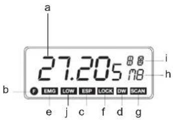
It shows:
a. channel selected number (from 1 up 40) or operative frequency
b. FUNC button activated
c. ESP: reducing noise device activated
d. DW: Dual Watch function activated
e. EMG: indicates channel being used or when the emergency channels are activated
f. LOCK: keyboard lock function activated
g. SCAN function activated
h. M1-M2-M3-M4-M5: memory channel indicator
i. Indicates the frequency band selected.
j. It appears when the radio transmits in low power (this condition happens only in certain frequency bands – see the chart at the end of this manual).
- "AM/FM" Indicator
It indicates the operative mode. FM: red LED; AM: green LED.
- "RX/TX" Indicator
LED indicating receiving or transmitting mode. RX: green LED; TX: red LED.
- "CB/PA" Selector
In the "CB" position, the unit operates as a transceiver. You can use the PA (public address) function only if you connect a speaker to the PA jack ("PA" visualized on the display). In this case the "MIC" knob controls the amplification level.
- FUNC button
With the SCAN button, you can:
- visualize the operative frequency (if you keep pressing the button for 3 seconds approx.), or the channel in use;
- activate the second functions of the "M" (M1/M5) buttons.
M1 / M2 / M3 / M4 / M5:
Midland 248 XL has the possibility to store and to recall, when necessary, 5 channels previously memorized.
To memorize one channel, follow the procedure herebelow:
A) Select the channel with the appropriate selector or the "UP/DN" buttons on the microphone;
B) Push the "FUNC" button: the display will show "F";
C) Keep pressing the "M1/EMG" button for 3 seconds: you will hear a "BIP" and the display will show "M1".
To memorize the other preset, repeat these steps and select another
memory different from 1.
To recall a channel previously stored, push the "FUNC" switch and the button of the desired memory.
These buttons have two functions; herebelow you will find their descriptions:
9. "M1 - EMG" switch
This switch allows the storing of the first memory and the recalling of the 2 emergency channels. "M1 - EMG" selects sequentially channels 9 / 19 (emergency) and the one in use.
10. "M2 - DW" button
"M2 - DW" stores the chosen channel in the M2 memory and activates the DUAL WATCH. This function allows the synchronization on two different channels at the same time:
when a signal on the second channel is received, the conversation on the first one is automatically interrupted and the receiver switches on the second channel. The monitoring starts again 5 seconds after the signal end.
To activate this function, operate as follows:
- Select the desired channel through the channel selector or the "UP/DOWN" buttons on the microphone;
- Keep the "DW" button pressed for about 3 seconds: you will hear a "BIP" and "DW" will flash on the display.
- Select the second channel with the same procedure;
- Press the button "DW" again for roughly 3 seconds: you will hear another "BIP"; the display will permanently show "DW" and will alternatively visualize the two selected channels.
11. "M3 - SCAN" switch
The two functions of this button are: memorization of the third channel in the M3 memory and "SCAN" function activation. In this case, you can automatically seek for a busy channel:
- turn the squelch clockwise until the background noise is no longer heard;
- press the "M3 - SCAN" button: "SCAN" will be shown on the display and the transceiver will automatically scan all the channels until a carrier is being received.
This function can be deactivated in three ways: pressing the PTT button, turning the channel selector or simply pushing any other button on the unit.
12. "M4/LCR - AM/FM" button
Stores the memory number 4 and selects the operative mode (AM/FM). AM: green LED; FM: red LED. If you select a frequency band operating in FM modulation only, this button activates the LCR function (Last Channel Recall).
13. "M5 - LOCK" switch
Pressing this button, you memorize the fifth (last) memory and activate the "LOCK" function (it allows the locking of the keyboard, channel selector and "UP/DN" buttons on the microphone, thus avoiding accidental use of the keys).
14. N.K. button
Pressing this switch, you activate the reducing noise device (see introduction).
15. "MIC" knob
The amplification of the voice in TX must be adjusted with this knob. The optimum level of the modulation must be found with the help of your receiving partner.
16. "RF" knob
It controls the reception sensitivity.
To increase sensitivity, simply turn it clockwise. Sensitivity decreases turning it counterclockwise.
17. "VOL" knob
It allows the switching on of the unit and sets the volume to a comfortable audio level.
18. "Squelch" knob
For the maximum receiver sensitivity, the control must be regulated exactly where the receiver background noise disappears.
REAR PANEL
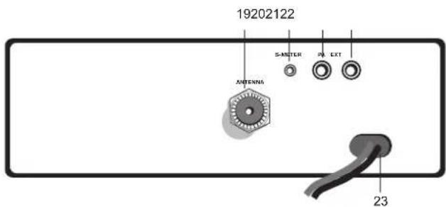
- Antenna connector (SO239 connector type).
- S.Meter jack: it allows an external "s meter" connection.
- "PA" jack: by connecting with an external loudspeaker, you can use the unit as an audio-amplifier.
- "EXT" jack: external loudspeaker jack (the internal loudspeaker is excluded).
- Power 12.6 Vdc: power supply cable.
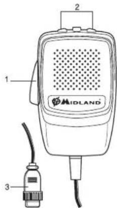
MICROPHONE
- PTT: transmission button
- UP/DOWN buttons: manual channel selector
- 6 pin microphone connector
INSTALLATION
Safety and convenience are the primary consideration for mounting any piece of mobile equipment. All controls must be readily available to the operator without interfering with the movements necessary for safe operation of the vehicle. Set the proper position in the car to install the transceiver using the supplied supporting bracket or eventually the slide bracket. Tighten the retaining screws. The fixing bracket must be close to metallic parts.
POWER SUPPLY
Be sure the transceiver is off. In the direct-voltage power supply, to observe the polarity is very important, even if the unit is protected against the accidental inversion:
Red = positive pole (+)
Black = negative pole (-)
The same colors are present on the battery and in the fuse box of the car.
Connect correctly the cable terminal to the battery.
ATTENTION
To obtain best performances we recommend to install the radio in a place with enough air circulation.
INSTALLING AN ANTENNA
- Place the antenna as high as possible.
- The longer is the antenna, the better will be the performance.
- If possible, mount the antenna in the center of whatever surface you choose.
- Keep the antenna cable away from noise sources, such as the ignition switch, gauges, etc.
- Make sure you have a solid metal-to-metal ground connection.
- Prevent cable damage during antenna installation.
WARNING. to avoid damage, never operate your CB radio without connecting a proper antenna. A periodical control of the SWR is recommended.
REPLACING FUSE
If you replace the fuse for DC power Cord, use F 5A 250V type. The parameters and the symbol of the fuse are indicated in the following label.

HOW TO OPERATE WITH YOUR MIDLAND 248XL
- Screw the microphone plug into the microphone jack.
- Make sure your antenna is securely connected to the antenna connector.
- Make sure the SQUELCH control is turned fully counterclockwise.
- Turn on the unit and adjust the volume control.
- Select your desired channel through the "UP/DN" buttons on the microphone.
- To transmit, press the PTT button and speak with a normal tone of voice.
- To receive, release the PTT button.
The frequency bands must be chosen according to the country you are in. Procedure:
- Switch off the unit.
- Turn it on while pushing the "N.K." button.
-
Rotate the "CHANNEL" knob and select the desired frequency band (see the chart here below).
-
To fix your selection, press the "LOCK" button.
NOTE: If you select a frequency band which operates in FM mode only, the "AM/FM" control activates the LCR function (Last Channel Recall).
NOTE: In the UK frequency band, you can select directly the EC band by pushing the "LCR-A/F" control for about 2 seconds.
| Displayed digits Country | |
| I Italy 40 CH | AM/FM 4Watt |
| I2 Italy 34 CH | AM/FM 4Watt |
| D Germany | 80 CH FM 4Watt / 12 CH AM 1 Watt |
| D2 Germany | 40 CH FM 4Watt / 12 CH AM 1 Watt |
| D3 Germany | 80 CH FM 4Watt / 40 CH AM 1 Watt |
| D4 Germany | 80 CH FM 4Watt / 40 CH AM 4 Watt |
| EU Europe 40 | CH FM 4Watt / 40 CH AM 1 Watt |
| EC 40 CH FM | 4Watt |
| E Spain 40 CH | AM/FM 4Watt |
| F France 40 | CH FM 4Watt / 40 CH AM 1 Watt |
| PL Poland 40 | CH AM/FM 4Watt |
| UK England | 40 CH FM 4Watt English frequencies + + EC 40 CH FM 4Watt frequencies |
ATTENTION!
The frequency band allowed all over Europe is 40CH FM 4W (EC) – See the "Restrictions on the use" table.
SPECIFICATIONS
GENERAL
Channels (see the Frequency band chart)
Frequency Range* 26.565 - 27.99125 MHz
Duty cycle (% on 1 hour).... TX 5% - RX 5% - Stand-by 90%
Frequency Control ....PLL
Operating Temperature Range -10°/+55°C
DC input voltage 12.6 Vdc ±10%
Size....150(L) x 45(H) x 175(D)mm
Weight 1Kg
RECEIVER
Receiving system....Dual conversion superheterodyne
Intermediate frequency .....I°IF:10.695 MHz II°IF:455 KHz
Sensitivity....0.5μV for 20dB SINAD in AM/FM
Audio output power @10% THD 2.0 W @ 8 Ohm
Audio distortion....Less than 8% @ 1KHz
Image rejection....65dB
Adjacent channel rejection 65dB
Signal/Noise ratio....45dB
Current drain at stand/by....12.6V: 450mA
TRANSMITTER
Output power 4W max
Modulation FM:1.8KHz ± 0.2kHz
AM: 85% to 95%
Frequency response 300 Hz/3 KHz
Output impedance....RF 50 Ohm unbalanced
Signal/Noise Ratio 40 dB MIN
Current drain max 12.6V: 2500 mA
A readily accessible disconnect device shall be incorporated in the installation wiring. The disconnect device shall disconnect both poles simultaneously.
Hereby, CTE International declares that Midland 248 XL is in compliance with the essential requirements and other relevant provisions of Directive 99/05/EC.
Inhaltsverzeichnis
Einleitung....2
REPLACEMENT DU FUSIBLE
7. Selector "CB - PA"
- All articles displaying this symbol on the body, packaging or instruction manual of same, must not be thrown away into normal disposal bins but brought to specialised waste disposal centres. Here, the various materials will be divided by characteristics and recycles, thus making an important contribution to environmental protection.
Produced or imported by:
CTE INTERNATIONAL s.r.l.
Via. R.Sevardi 7 - 42124 Mancasale Reggio Emilia Italy
Imported by:
ALAN-NEVADA UK
Unit 1 Fitzherbert Spur Farlington Portsmouth Hants. P06 1TT
United Kingdom
www.nevada.co.uk
The use of this transceiver can be subject to national restrictions.
Read the instructions carefully before installation and use.
Importado por:
ALAN COMMUNICATIONS, S.A.
C/Cobalt, 48 - 08940 Cornellá de Llobregat España
Tel. 902 384878 - www.midland.es

- FUNCTION AND LOCATION OF THE CONTROLS
- "M1 - EMG" switch
- "M2 - DW" button
- "M3 - SCAN" switch
- "M4/LCR - AM/FM" button
- "M5 - LOCK" switch
- N.K. button
- "MIC" knob
- "RF" knob
- "VOL" knob
- "Squelch" knob
- REAR PANEL
- MICROPHONE
- INSTALLATION
- POWER SUPPLY
- ATTENTION
- INSTALLING AN ANTENNA
- REPLACING FUSE
- HOW TO OPERATE WITH YOUR MIDLAND 248XL
- ATTENTION!
- SPECIFICATIONS
- GENERAL
- RECEIVER
- TRANSMITTER
- Inhaltsverzeichnis
- REPLACEMENT DU FUSIBLE
- Selector "CB - PA"
- CTE INTERNATIONAL s.r.l.
- ALAN-NEVADA UK
- www.nevada.co.uk
- ALAN COMMUNICATIONS, S.A.
Brand : MIDLAND
Model : 248XL
Category : Walkie-talkie