
ALAN 100 PLUS B - Talkie Walkie MIDLAND - Free user manual and instructions
Find the device manual for free ALAN 100 PLUS B MIDLAND in PDF.
| Product type | CB walkie-talkie |
| Brand | Midland |
| Model | ALAN 100 PLUS B |
| Dimensions (L x H x D) | 124 x 38 x 190 mm |
| Weight | 1.2 kg |
| Power supply | 13.8 V DC (negative ground) |
| Current consumption | FM: 1.3 A; AM: 1.8 A |
| Frequency range | 26.965 - 27.405 MHz (CB band) |
| Modulation | AM/FM |
| Output power | 4 W max |
| Antenna impedance | 50 ohms |
| Receiver sensitivity | 1.0 µV for 20 dB SINAD |
| Intermediate frequencies | 1st IF: 10.7 MHz; 2nd IF: 455 kHz |
| Audio power | 4.5 W max |
| Squelch | Adjustable (1.2 µV to 1 mV) with hysteresis |
| Emergency button | Selects channel 9 or 19 |
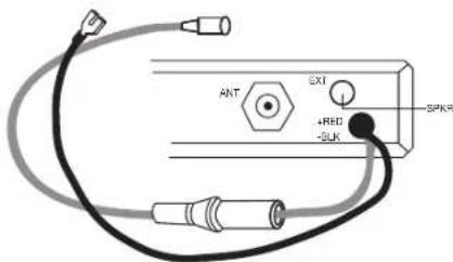
| External connectors | External speaker (EXT-SPKR), antenna (PL) |
| Display | Green screen showing channel |
| Operating temperature | Use in vehicle or base station |
| Maintenance and cleaning | Clean with a soft dry cloth. Do not use solvents. |
| Safety | Do not transmit without antenna. Disconnect power before any maintenance. |
| Warranty and repairability | Spare parts available on request. Repair by a professional. |
Frequently Asked Questions - ALAN 100 PLUS B MIDLAND
User questions about ALAN 100 PLUS B MIDLAND
0 question about this device. Answer the ones you know or ask your own.
Ask a new question about this device
Download the instructions for your Talkie Walkie in PDF format for free! Find your manual ALAN 100 PLUS B - MIDLAND and take your electronic device back in hand. On this page are published all the documents necessary for the use of your device. ALAN 100 PLUS B by MIDLAND.
USER MANUAL ALAN 100 PLUS B MIDLAND
Italy - Restrictions on the use - According to the Italian Frequency Allocation Table, issued on the G.U. No. 169 - Supplement 146 - of 20th July 2002 - note 49G, the standard in AM modulation needs a radiating system with a gain not higher than -6dB, such as, for example, with the antenna "PC8" with original cable.
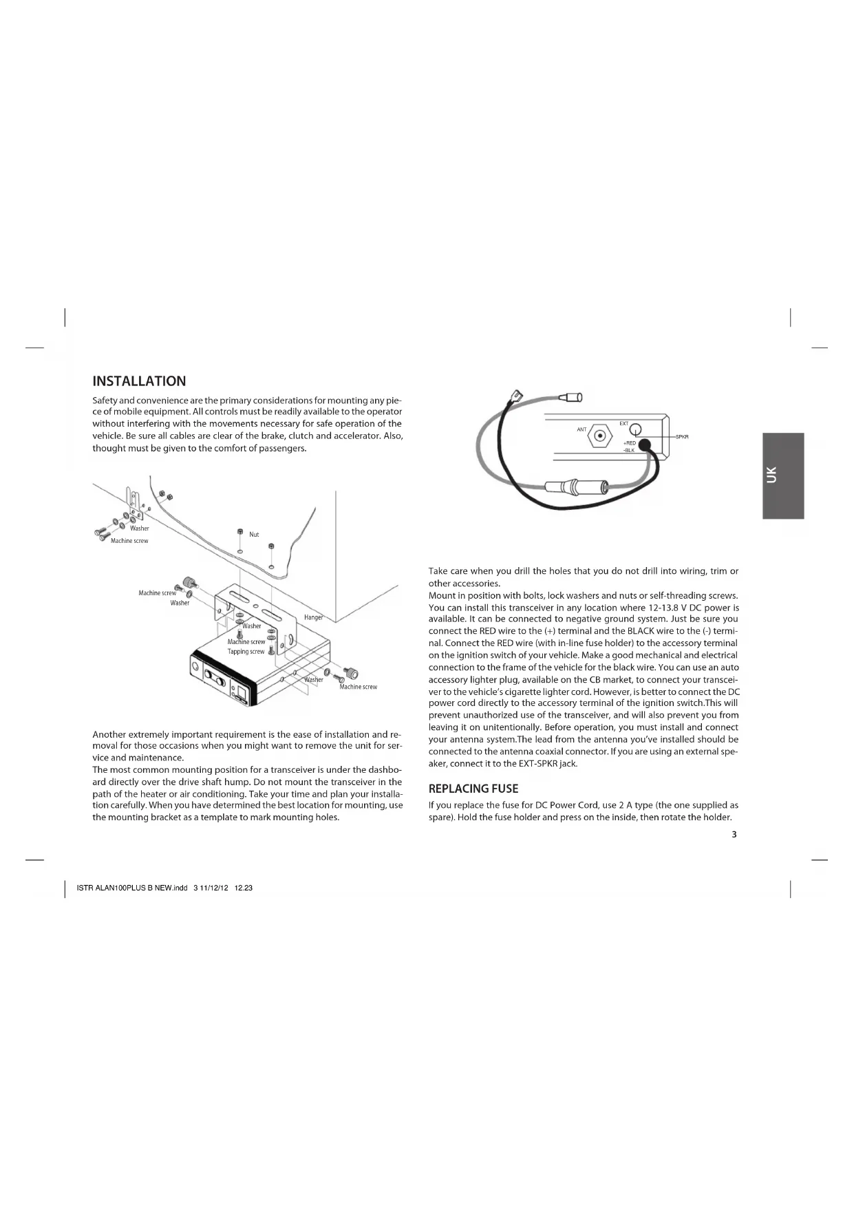
Phase Locked Loop circuitry gives precise frequency control and stability over all 40 channels: pinpoint channel tuning accuracy with separate scan up and down controls.
Ceramic filters give superior selectivity and freedom from adjacent channel interference.
Green Led channel indicator clearly shows which channel is activated.
Red Led (TX) and Green Led (RX) show the operative modality:
TX=transmission;
RX=reception
Hysteresis-type Squelch circuit automatically compensates for signal fading to eliminate signal "chopping" during message reception.
Extremely sensitive.
Condenser type plug-in communications microphone provides superior transmission.
Emergency switch lets you switch to channel 9 or 19 - instantly.
Jacks for external speaker let you hook up other speaker systems.
Works with negative ground 12 - 13.8 V DC.
COMMANDS
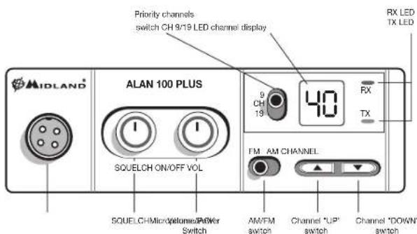
External speaker jack
INSTALLATION
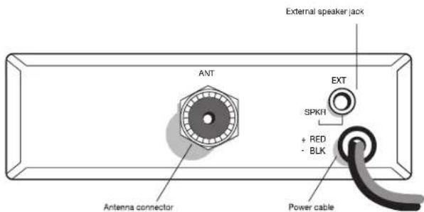
Safety and convenience are the primary considerations for mounting any piece of mobile equipment. All controls must be readily available to the operator without interfering with the movements necessary for safe operation of the vehicle. Be sure all cables are clear of the brake, clutch and accelerator. Also, thought must be given to the comfort of passengers.
Another extremely important requirement is the ease of installation and removal for those occasions when you might want to remove the unit for service and maintenance.
The most common mounting position for a transceiver is under the dashboard directly over the drive shaft hump. Do not mount the transceiver in the path of the heater or air conditioning. Take your time and plan your installation carefully. When you have determined the best location for mounting, use the mounting bracket as a template to mark mounting holes.
Take care when you drill the holes that you do not drill into wiring, trim or other accessories.
Mount in position with bolts, lock washers and nuts or self-threading screws. You can install this transceiver in any location where 12-13.8 V DC power is available. It can be connected to negative ground system. Just be sure you connect the RED wire to the (+) terminal and the BLACK wire to the (-) terminal. Connect the RED wire (with in-line fuse holder) to the accessory terminal on the ignition switch of your vehicle. Make a good mechanical and electrical connection to the frame of the vehicle for the black wire. You can use an auto accessory lighter plug, available on the CB market, to connect your transceiver to the vehicle's cigarette lighter cord. However, is better to connect the DC power cord directly to the accessory terminal of the ignition switch. This will prevent unauthorized use of the transceiver, and will also prevent you from leaving it on unintentionally. Before operation, you must install and connect your antenna system. The lead from the antenna you've installed should be connected to the antenna coaxial connector. If you are using an external speaker, connect it to the EXT-SPKR jack.
REPLACING FUSE
If you replace the fuse for DC Power Cord, use 2 A type (the one supplied as spare). Hold the fuse holder and press on the inside, then rotate the holder.
ANTENNA SYSTEM
A mobile antenna system is not limited to the antenna only. The transmission line as well as the vehicle are important factors in the total antenna system. Therefore, you must use the correct type of transmission line and mount the antenna securely in a position that will give you optimal results. Use coaxial cable with an impedance of 50 Ohms. We suggest type RG 58/U for lengths under 2.5 m or RG 8/U for longer lengths. Generally speaking, you should keep the length of the transmission line to a minimum.
The above discussion is as important for reception as it is for the transmission. If a mismatch exists between the antenna and the receiver, the excellent sensitivity and signal-to-noise radio of the receiver circuit will be defeated.
MOBILE ANTENNAS
A few general rules should help you to install any mobile antenna properly. Keep it as far as possible from the main bulk of the vehicle.
During operation, it must be vertical, and rigid enough to remain vertical when the vehicle or boat is in motion.
Mount it as far as possible from sources of noise (ignition system, gauges, etc.) and keep the transmission line away from these noise sources.
An antenna mounted in a boat requires a good ground connection. This can be either a metal hull or a ground made of tin-foil or copper sheeting. This ground should cover an area of at least 1m^2 or more. Be sure the transceiver also has an adequate ground.
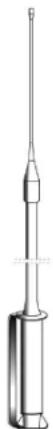
There are many types of mobile CB antennas: a full quarter-wave length whip, a centerloaded whip, top loaded whip and the base loaded type.
A vertically polarized whip antenna is best suited for mobile service. It is omni-directional.
If it's the loaded type, you will find it a phisically shorter antenna. But, for greater efficiency the 2.5 m long, full quarter-wave whip is better. Antenna length is directly related to efficiency.
Generally, the longer it is the more efficient.
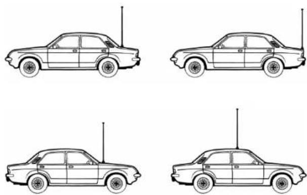
There are many possible antenna locations on a car. Four of the most common are shown and discussed on the following.
Roof Mount - In this position the antenna radiates equally in all directions. Since the normal 1/4 wavelength whip antenna is too long for roof mounting
on a vehicle, the antenna is shortened and loading coil is used to provide the proper electrical length. Our fiberglass roof mount is a good durable antenna.
Front Cowl Mount - The radiation pattern is slightly greater in the direction of the rear fender opposite the side on which the antenna is mounted. However, the front position offers a number of advantages. The CB antenna can be easily mounted. It can double as both the CB and the standard auto radio antenna by employing a two-way coupler. Ask about our complete line of antennas.
Rear Deck Mount - The radiation pattern is stronger in the direction of the front fender opposite the side on which the antenna is mounted. In this position you can use a full quarter-wave antenna or a shorter loaded whip. Here you might consider one of the full 2.5 meters whips.
Bumper Mount - The antenna radiates in a pattern directly in front of and to the rear of the vehicle, with maximum radiation directly away from the vehicle, in a horizontal plane. Despite its fairly irregular pattern, a bumper-mounted full-length whip antenna will normally give the best results. Removing the antenna is simple and will leave no holes in the car.
BASE STATION ANTENNA
While your transceiver is designed for mobile operation, you might wish to use it as a base station unit, in conjunction with a 12 - 13.8 V 2 A DC power supply. If you decide to use your transceiver as a base station, choose an antenna designed to operate most efficiently as a base station antenna. For example, the 1/2 wave antenna is a high-efficiency radiator with omnidirectional characteristics. It performs as well in most applications as does the ground plane. You can use this type of antenna for medium-long range communications.
USING YOUR TRANSCEIVER
Do not transmit without a suitable antenna or 50 Ohm load connected to the antenna connector.
To receive:
- Check that the unit is properly connected to a source of 12-13.8 V through the in-line fuse and red wire.
- Make sure that the antenna is attached.
- Connect the mic plug to the mic jack.
- Select AM or FM mode.
- Set the emergency switch to the center position.
- Set the Squelch control to maximum counterclockwise position.
- Turn on the unit by rotating the ON/OFF/VOL control.
- Set channel selector to the desired channel.
- Adjust the volume to a suitable listening level.
- Adjust Squelch to cut out annoying background noise when no signal is being received. To do this, set the Channel Selector to a channel where no signals are present or wait until signals cease on your channel.
Then, rotate the Squelch control in a clockwise direction to the point where the background noise just stops. Now, when a signal is present, you will hear it, but will not be disturbed by noise on the channel between signals.
When properly set, the Squelch keeps the receiver "dead" until a signal comes in on that channel. However, do not set the Squelch too high, otherwise weak signals will not be able to open the Squelch circuit. To receive very weak signals, it is best to leave Squelch set to the minimum position by rotating the control maximum counterclockwise. The Squelch circuit in your Transceiver is
an advanced design. It uses an operational amp IC to accomplish a hysteresis action. The result is that when you set the Squelch for a precise signal level, if that signal level increases or decreases in strength, the Squelch circuit will follow this change. With conventional Squelch circuit, often a signal which changes strength get "chopped" by the Squelch circuit and you lose a portion of the message.
With a hysteresis Squelch, you get it all.
To Transmit:
- Select the desired channel.
- Press the push-to talk button on the microphone and hold it an angle about 5-7 cm from your mouth and speak in a normal voice.
- To receive, release the push-to-talk button.
Be sure the mic plug is firmly connected to the jack.
NOTE: shouting into the mic will not increase your power or signal. An internal circuit automatically sets the mic signal for maximum modulation, so speaking loudly will give no advantage.
A 4 Ohm speaker, rated at 3-10 watts, should be used for this function. Plug the speaker into the EXT SPKR Jack at the rear of the transceiver. When the external speaker is plugged in, the internal speaker is disconnected. You can now monitor all incoming signals through your remote speaker.
TECHNICAL SPECIFICATIONS
RECEIVER
Frequency coverage 26.965 to 27.405 MHz
Sensitivity . better than 1.0 V for 20 dB SINAD
Adjacent Channel Rejection 60 dB at 10 kHz; 70 dB for 20 KHz
Intermediate Frequency 1st IF=10.7 MHz; 2nd IF=455 KHz
Audio Output power 4.5 watts max
Frequency Response (-6dB) 450-2500 Hz
Squelch adjustable from 1.2 V to 1mV
TRASMITTER
Frequency coverage 26.965 to 27.405 MHz
Duty cycle 5/5/90
Output Power 4 watts max
Type of modulation AM/FM
Max Deviation 2.5 KHz FM; 80% AM
Spurious Radiation 62 dB or better
Frequency Tolerance better than 0.002%
Antenna impedance 50 Ohm
Power supply 13.8V
Current Drain FM: 1.3 A; AM: 1.8 A
Dimensions 124x38x190 mm
Weight 1.2 kg
Specifications are subject to change without notice.
A readily accessible disconnect device shall be incorporated in the installation wiring.
The disconnect device shall disconnect both poles simultaneously.
INHALT
Meyiotn anoklan 2.5 KHz FM; 80% AM
Anoppi np apmuovkov 62 dB n kaUTepn
Avox ouvoTuw KaUrePn ano 0.002%
Avriotaan Kepaiac 50 Ohm
Tropoosola 13.8V
Katavawon peumuotoc FM:1.3A;AM:1.8A
△aotaoic 124x38x190mm
Bapoc 1.2 kg
Ta yaapaktnpiatakTc oukeunuc unokivtae alayx wipic npotepn EI donolon.
To kaawio ouvdeonc tropoosooiaoc tou noptoekn kataaayei e doakpodeskct ekoala npoobaoiouoc.
Oi akpoδekTeC kaIa 0a elva a anouvDcovTuTOxpoVa kai ano Touc duo nolouc.
CUPRINS
Descriere.. pag.2
Instalarea . . .pag. 3
Inlocuire siguranta . pag.4
Antena ca systemd . pag.4
Antene mobila . pag.4
Produced or imported by:
CTE INTERNATIONAL s.r.l.
Via.R.Sevardi 7-42124 Mancasale Reggio Emilia Italy
Imported by:
ALAN-NEVADA UK
Unit 1 Fitzgerald Spur Farlington Portsmouth Hampshire P06 1TT
United Kingdom
www.alan-uk.com www.midland-uk.com
The use of this transceiver can be subject to national restrictions.
Read the instructions carefully before installation and use.
Importado por:
ALAN COMMUNICATIONS, S.A.
C/Cobalt, 48-08940 Cornellá de Llobregat España
Tel. 902 384878 - www.midland.es

Brand : MIDLAND
Model : ALAN 100 PLUS B
Category : Talkie Walkie