USER MANUAL Futura Gutmann
Thank you for deciding to purchase a GUTMANN exhaust hood.
Please carefully read the following information and explanations regarding the proper use of your new GUTMANN hood before first using it. Please take note of our cleaning recommendation so that you can enjoy your new advice for as long as possible.
Safety Instructions
Installation, connection, startup and repairs may only be conducted by a service technician. This service technician can determine the appropriate fasteners and exhaust air flow of the exhaust hood. The fasteners must be suitable for the weight of the exhaust hood and the load of the surface. Note the resistance of the enclosed screw anchors. These have the following values, depending on the surface: Screw Anchor 10mm Concrete B25 9.4 kN Brick Z20 5.2 KN lime sandstone KSV20 4.8 KN Consultant a construction professional, e.g. a structural engineer or architect for safe installation of the exhaust hood into other surfaces.
Risk of Injury!
Sharp edges may be located on the hood body as a result of the manufacturing process. Protective gloves should be worn during installation.
Risk of Electrical Shock!
The network voltage must be in accordance with the information on the label. This is located inside the hood, near the filter. Only connect the exhaust hood to a standardly installed outlet. The outlet must be easily accessible after installation in order to be able to separate the exhaust hood from the network voltage if necessary. In the event of a fixed connection (e.g. if a suitable outlet is not available), the exhaust hood may only be connected to the network voltage by an electrician. The exhaust hood must be connected to an individual electrical circuit with an energy-isolating device for a fixed connection. Switches with one contact opening of at least 3mm and all-pole switches, e.g. LS switches and fuses are deemed to be energy-isolating devices. Turn off the network voltage current before working on the electrical connection of the exhaust hood. Before drilling fastener holes, ensure that no electrical conduits will be damaged by the drilling. The electrical connection must be prepared in such a manner that the exhaust hood can be easily connected to it. Local conditions must be complied with.
Exhaust Air Flow (Exhaust Operation)
The exhaust may only be fed into a chimney which can be used for the exhaust gas of devices with fuel (e.g. gas). Official regulations for the dissipation of the exhaust must be complied with. The exhaust path must be prepared in such a manner that the exhaust hood can be easily connected to it. The exhaust hose must be laid out in a manner in which it is not bent. During simultaneous operation of an exhaust hood for exhaust purposes and other heat producing appliances dependent upon the air in the room (e.g. wood, gas or oil fueled devices) in one room, deadly flammable gases could be fed back into the room through negative pressure. Therefore, the operator must provide sufficient fresh air at all times. The negative pressure in the room may not be greater than 4 Pa (0 mbar).
Heat Producing Appliances for Fixed Fuel Installation of the exhaust hood above a heat producing appliance for fixed fuel which carries a risk of fire (e.g. flying sparks) is only permissible if the heat producing appliance has a closed, non removable lid.
Safety Warning for Operating Moving Parts
Please make sure that there are no objects in the immediate vicinity (ca. 5 cm) of the rosette cover while operating moving parts. Objects which fall into the hood shaft could damage the hood!
Danger
Do not place any parts of the body in the vicinity of the hood while operating moving parts. Please also ensure that no other persons (especially children) are in dangerous area. There is a risk of serious injury from crushing!
The hood is additionally equipped with an electronic safety circuit. This stops the hood in the event of too strong a resistance during the operation of moving parts. The hood can then be placed back into operation after remedying the cause of the disturbance by pressing button 1.
Subject to technical changes!
General Functionality:
This exhaust hood has been specially developed for the exhaust of cooking vapors in private households. This series of hoods concerns so-called trench ventilation which retracts into the counter after use and thus remains „invisible". The unmistakable form of the hood body, which strengthens the functionality, guarantees high performance using innovative edge suction in conjunction with the use of a high quality metal filter. The entire module disappears completely into the counter at the push of a button. The rising cooking vapors are sucked into the exhaust hood and through a metal filter. The metal filter is held in place in the hood body with by magnets. The metal filter is covered by a glass element. Access to the metal filter is guaranteed via the manual positioning of the glass element. The exhaust power is regulated via the control panel. The respective power level is displayed via LEDs. The exhaust hood is finished in stainless steel in conjunction with glass elements for hygienic reasons.
The hood model range FUTURA is produced in two variants, which are:
Futura 01 ML = with retractable hood body and radio remote control
Futura 02 ML = with fixed hood body and toggle switch
Product Description
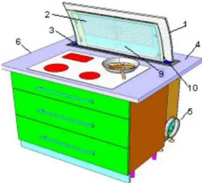
1 Hood Body
2 Safety Glass Panel
3 Cover Rosette
4 Counter
5 Exhaust Connection
6 Cooking Surface
7 Sealing Flap
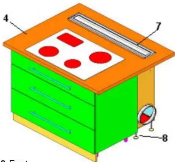
8 Feet
9 LED
10 ON/OFF Switch, Exhaust Power
Instruction Manual
The functions of hood model series Futura 01 ML and Futura 02
ML differ as follows:
- Operation via radio remote control (only Futura 01 ML)
- Operation via toggle switch (Futura 02 ML)
Operating instructions (only Futura 01ML) The hood must be extended before cooking. To do so, press button 1 on the remote control. Warning: Do not place any parts of the body in the vicinity of the hood while operating moving parts. Please also ensure that no other persons (especially children) are in dangerous area. There is a risk of serious injury from crushing!
The hood is additionally equipped with an electronic safety circuit. This stops the hood in the event of too strong a resistance during
the operation of moving parts. The hood can then be placed back into operation after remedying the cause of the disturbance by pressing button 1. The functions of the hood as well as the power level of the external
motor can be controlled in two different ways:
Remote Control: (only Futura 01 ML)
The control panel consists of a radio remote control with 6 buttons which can be programmed with different functions.
Button 1 = ON / OFF Hood
Button 2 = EXTEND/RETRACT Hood
Button 3 = Exhaust Power + / -
Button 4 = Exhaust Power max.
Button 5 = Cool Down Period
Extend Hood (2)
The hood extends from the counter by pressing button (2). Press the button again, on the hood will retract into the counter.
Press button (1) to turn on the hood. The hood will begin running at a low level (one LED illuminated). Exhaust Power The exhaust power is controlled by pressing button (3) multiple times. The individual levels, however, must be switched to sequentially. 4 different power levels can be selected. The respective power level will be displayed by the LEDs.
Automatic Cool Down Period
Press button 5 (the green LED will blink) and then the automatic cool down period will be activated automatically. The exhaust hood will progressively switch from level 3 down to level 1 and run at that level for approximately 15 minutes before turning off.
Clean Grease Filter Alert
The metal filter must be cleaned when the red LED lights up (see section on cleaning and care). The filter saturation display will light up after a maximum of 15 hours of operations or every 14 days (even if there is no cooking performed).
Operation via toggle switch : Futura 02 ML (situated on the hood body next to the plate)
Pressing the switch to the right: fan power control. Pressing the switch to the right for 3 seconds: Hood switches off. The filter saturation display is also reset via this switch. For this, please press the switch to the right until the red LED goes out.
LED Displays (9)
| Cool Down: | Green LED |
| Level 1: | Green LED |
| Level 2: | Green LED |
| Level 3: | Green LED |
| Intensive Level: | Green LED |
| Filter Saturation Indicator: Red LED |
LED 1: Indicates operational status ON/OFF
LED 1: blinking: Indicates automatic cool down period
LED 2: Exhaust power level 1 (low)
Button 3: Press the remote control once
LED 3: Power level 2 (medium)
Button 3: Press the remote control twice
LED 4: Power level 3 (high)
Button 3: Press the remote control three times
LED 5: Intensive level (motor automatically returns to level 3 after 3 minutes)
Button 3: On the remote control
LED 6: Filter Saturation Indicator
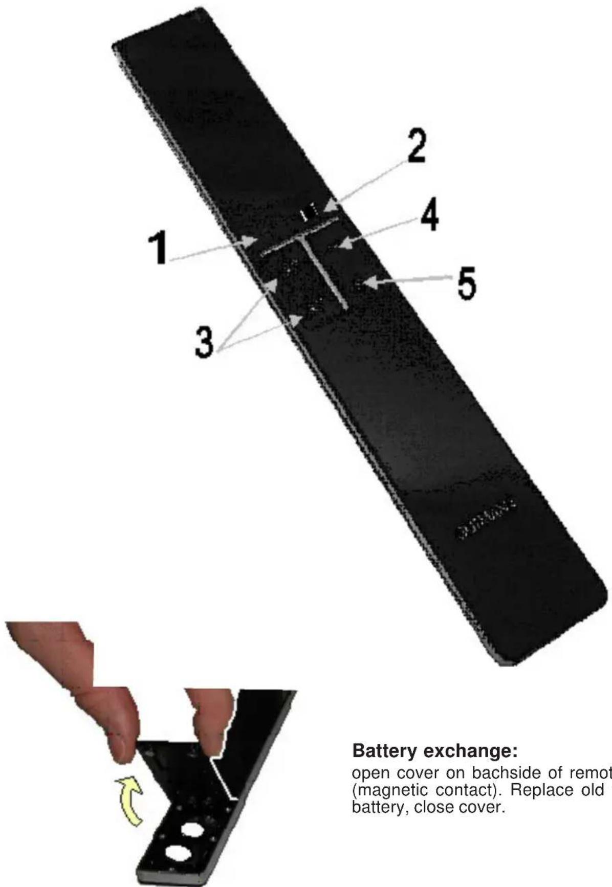
Battery exchange:
open cover on Bachside of remote control (magnetic contact). Replace old with new battery, close cover.
Cleaning and Care
Cleaning the Surface
Risk of Electrical Shock!
Separate the exhaust hood from the electrical supply by removing the plug from the outlet or tripping the fuse. Please make sure that no water enters the device during cleaning.
Early cleaning of the surfaces prevents toilsome removal of deep-rooted debris later. Please only use standard detergent or all purposes cleaners which are suitable for stainless steel/aluminum surfaces. Never use scouring cleaners or steel wool.
After cleaning the hood, treat the stainless steel surfaces with an appropriate preserving agent. Painted surfaces should be cleaned with a mild detergent and a very soft cloth. The control panel must only be cleaned with a soft, damp cloth.
Remove / Clean the Grease Filter
Danger of Fire!
The performance of the exhaust hood is affected by greasy debris; the risk of fire increases with the amount of deposits. In order to avoid the risk of fire, be certain to regularly clean the metal filter.
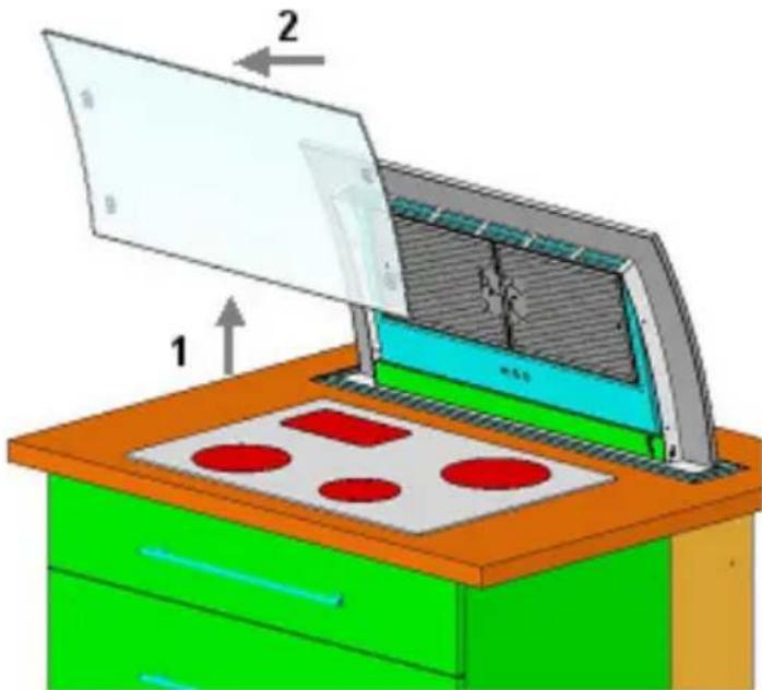
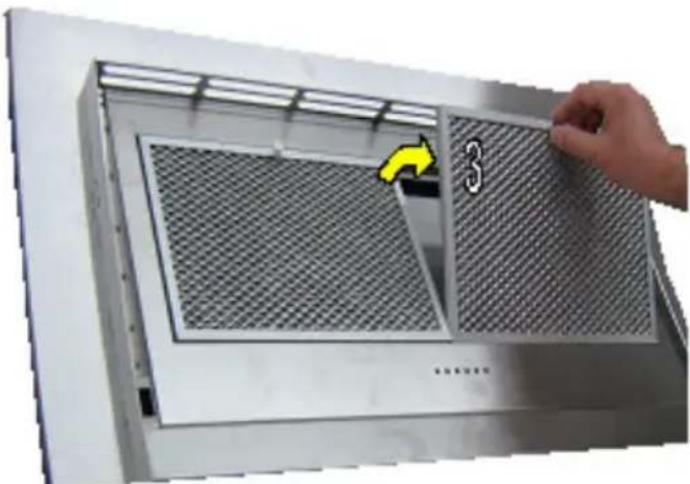
The metal filter must be cleaned every two weeks, at the latest.
In order to be able to remove the metal filter, the glass element must first be removed. To do so, hold the glass element tightly on the sides with both hands and push it upwards (1) until the glass element comes out of the guides. The glass element can now be removed from the front (2). The metal filter is now freely accessible and can be removed from the front (4) after the guard (3) has been pressed. Reassembly takes place in the reverse order.
The metal filter is best cleaned in a dishwasher with gentle dishwasher detergent.
The manufacturer offers no guarantee in the event of possible discoloration through the use of aggressive cleaning products. Temperatures above 65 degrees should also be avoided.
Warning: Please do not use any 3 phase cleaners or clean the filter in a commercial dishwasher. Cleaning with aggressive products such as benzene, acetone, trichloroethylene, et cetera will lead to the destruction of the filter!
Replace the metal filter after cleaning and then replace the glass element.
Malfunctions
Please consult our customer service immediately if the following malfunctions occur:
- The exhaust hood is making unidentifiable noises and you cannot determine a malfunction after inspecting the quality of ventilation;
- The motor is not running properly (e.g. it is making strange noises) or is defective;
- The switch is not functioning properly.
Please be certain to provide the type designation of your model as well as the accompanying serial number. This information can be found on the label located near the filter inside the hood.
Disposal
Packaging
The packaging of the exhaust hood is recyclable. Cardboard and polyethylene foil (PE) are used as packaging materials. These materials are environmentally compliant and should be disposed of as per the valid regulations of the respective location.
Exhaust Hood
Your local authorities will be happy to advise you regarding the environmentally friendly disposal of old household appliances.
Environmental Instructions
All GUTMANN models are labeled as per European Directive 2002/96/EG on Waste Electrical and Electronic Equipment (WEEE). This guideline provides the basic conditions valid for the EU-wide return and recycling of old appliances. Please consult your dealer for the current disposal methods.
Connection to the electrical network:
230 V / 50 Hz, max. 650 Watt
Instructions de commande hotte de Futura:
Chere cliente, cher client,
Option: Glas Touchpanel
1 Lüfterleistung