HSS1380A - Snow blower Honda - Free user manual and instructions
Find the device manual for free HSS1380A Honda in PDF.
Frequently Asked Questions - HSS1380A Honda
User questions about HSS1380A Honda
0 question about this device. Answer the ones you know or ask your own.
Ask a new question about this device
Download the instructions for your Snow blower in PDF format for free! Find your manual HSS1380A - Honda and take your electronic device back in hand. On this page are published all the documents necessary for the use of your device. HSS1380A by Honda.
USER MANUAL HSS1380A Honda
Originalinstructions
MANUELDEL'UTILISATEUR
Noticeoriginale
BEDIENUNGSANLEITUNG
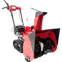
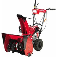
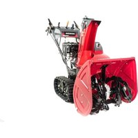
This manual covers the operation and maintenance of Honda snowblower: HSS970/HSS1380.
Allinformationinthispublicationisbasedonthelatestproduct informationavailableatthetimeofapprovalforprinting.
HondaMotorCo., Ltd. reserves the right to make changes at any time without notice and without incurring any obligation.
Nopartofthispublicationmaybereproducedwithoutwritten permission.
This manual should be considered a permanent part of the snowblowerandshouldremainwiththesnowblowerifitisresold.
Payspecialattentionostatementsprecededbythefollowingwords:
WARNING Indicatesastrongpossibilityofseverepersonaljuryordethatifnstructionsarenotfollowed.
CAUTION: Indicatesapossibilityofpersonalinjuryorequipment damageifinstructionsarenotfollowed.
NOTE: Giveshelpfulinformation.
If a problem should arise, or if you have any questions about your snowblower, consultanaauthorizedHondadealer.
WARNING
Operatingthisequipmentrequirespecialefforttoensurethesafety of the operator and the safety of others. Read and understand this Owner's Manual before operating thisequipment; failure to do so could result in personal injury or equipment damage.
Theillustrationshereinaremainlybasedon: EWStyle.
- Theillustrationmayvaryaccordinglytothetype.
Disposal
Topprotecttheenvironment,donotdisposeofthisproduct, battery,engineoil,etc.carelesslybyleavingtheminthewaste. Observethelocallawsandregulationsorconsultyourauthorized Hondadealerfordisposal.
1.SAFET 2.SAFET CE mark location 10 3.COMPC
4.CONTROLS. 13 5.PRE-OF 6.STARTI 7.SNOWI 8.STOPPI
9.MAINTENANCE 53
10. TRANSPORTING 66
11. STORAGE 69
12. TROUBLESHOOTING 73
13. SPECIFICATIONS 74
MAJOR Honda DISTRIBUTOR ADDRESSES. Inside back cover "ECDclarationofConformity CONTENT OUTLINE. Inside back cover
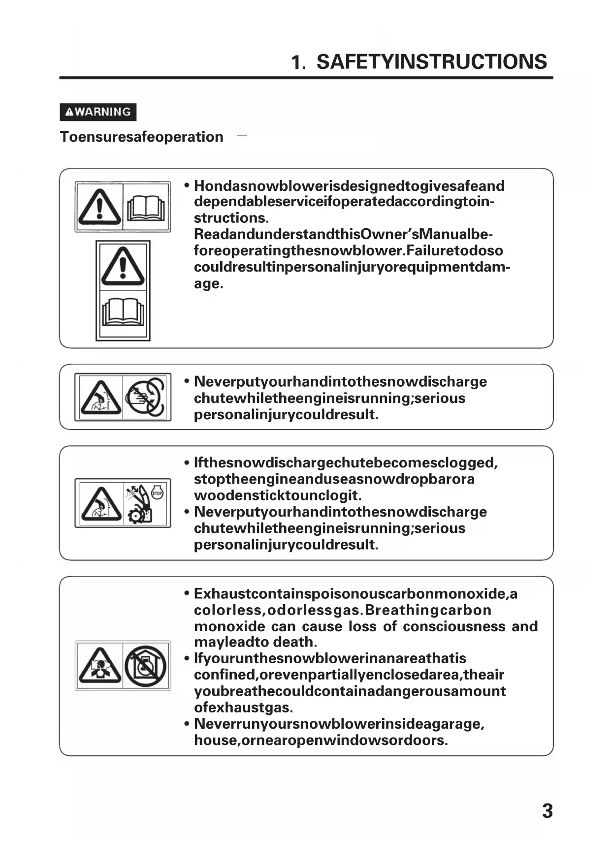
WARNING
Toensuresafeoperation
- Hondasnowblowerisdesigntogivesafeand dependableserviceifoperatedaccordingtoninstructions.
ReadandunderstandthisOwner'sManualbeforeoperatingthesnowblower.Failuretodosocouldresultinpersonalinjuryorequipmentdamage.
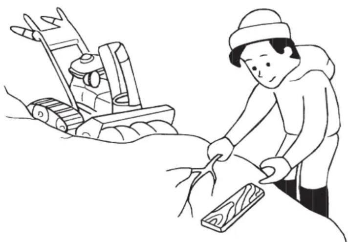
- Neverputyourhandintothesnowdischarge chutewhiletheengineisrunning;serious personalinjurycouldresult.
- Ifthesnowdischargechutebecomesclogged, stoptheengineanduseasnowdropbarora woodensticktounclogit.
- Neverputyourhandintothesnowdischarge chutewhiletheengineisrunning;serious personalinjurycouldresult.
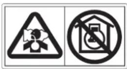
- Exhaustcontainspoisonouscarbonmonoxide,a colorless,odorlessgas. Breathingcarbon monoxide can cause loss of consciousness and mayleadto death.
- Ifyourunthesnowblowerinanareathatis confined,orevenpartiallyenclosedarea,theair youbreathecouldcontainadangerousamount ofexhaustgas.
- Neverrunyoursnowblowerinsideagarage, house, ornearopenwindowsordoors.
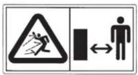
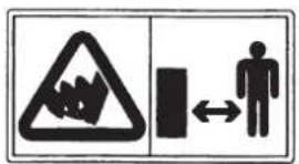
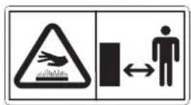
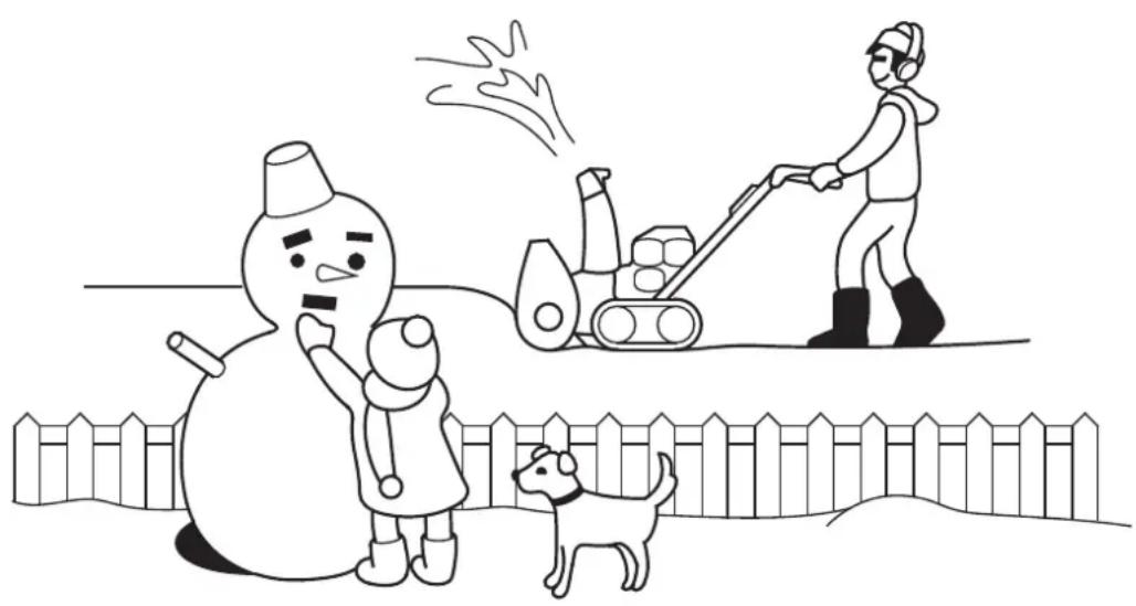
- Keepallpersonsandpetsawayfrom the snowblowerarea.
- Neverstandorworkaroundorneartheauger whiletheengineisrunning. Yourfeetmaybe caughtontheaugerwhentheauger is accidentallystarted, increasingtheriskof seriouspersonalinjury.
- Ahotexhaustsystemcancauseseriousburns. Avoidcontactiftheengineeringhasbeenrunning.
Gasolineisextremelyflammableandis explosiveundercertainconditions.
- Donotsmokeorallowflamesorsparksinthe areawherethesnowblowerisrefueledorwhere gasolineisstored.
- Donotoverfillthefueltank,andmakesurethe fueltankcapisclosedsecurelyafterrefueling.
- Refuelinawell-ventilatedareawiththeengine stopped.
- Keepflamesandsparksa wayfromthebatteries. Batteriesproduceexplosivegasthatcancause explosion.
- Handlethebatteryelectrolytewithextremecare asitcontainsdilutesulfuricacid.Contactwith yourskinoreyescanburnyouorcauselossof youreyesight.
- Donotallowchildrenandotherpeoplepototouch abatteryunlessstheyunderstandproper handlingandhazardsofthebatteryverywell.

- Donotuseabatterywiththeelectrolyteator belowthelowerlevelmark.Itcanexplode causingseriousinjury.

- Weartheeyeprotectionandrubbergloveswhen handlingthebatteries,oryoucangetburnedor loseyoureyesightbythebatteryelectrolyte.

- Readthismanualcarefullyandunderstandit beforehandlingthebatteries.Neglectofthe instructionscancausepersonaljuryand damagethesnowblower.
Operatorresponsibilities
- Knowhowtostopthesnowblowerquickly, and understand the operationofallcontrols.
- Neverpermitanyonetoooperatethesnowblowerwithoutproper instruction. If people or pets suddenly appear in front of the snowblowerwhileitisinoperation,immediatelyreleasetheauger and drive clutch levers to stop the snowblower and avoid possible injuryfromrotatingaugerblades.
WARNING
Toensuresafeoperation —
- Alwaysmakeapre-operationcheck(pagesthro@gh)before 34 youstarttheengine.Youmaypreventanaccidentorequipment damage.
- Hondasnowblowersaredesignedtogivesafeanddependable service if operated according to instructions. Read and understand this Owner's Manual before operating the snowblower. Failure to dosocouldresultinpersonalinjuryorequipmentdamage.
- Beforeoperatingthesnowblower,inspecttheareainwhichyou are goingtoclearnsnow.Removedebrisandotherobstaclesthesnowblowermightstrikethrow,astheymaycauseinjuryordamagetothesnowblower.
- Inspectthesnowblowerbeforeoperatingit.Repairanydamageand correctanymalfunctionbeforeoperation.
If you hit an obstacle while operating the snowblower, stop the engine immediately, and checkford damage. Damaged equipment may increase the possibility of injury during operation.
- Donotusethesnowblowerwhenvisibilityispoor.Under conditionsofpoorvisibility,thereisagreaterriskofstrikingan obstacleorcausinginjury.
- Neverusethesnowblowertoclearsnowfromagravelroador driveway, as rocks may be picked up and ejected. They may cause injurytobystanders.
WARNING
- Adjustthesnowdischargechutetoavoidhittingtheoperator, bystanders, windows, and other objects with the ejected snow. Stay clear of the snow chuter while the engine is running.
- Childrenandpetsmustbekeptawayfromtheareaofoperationto avoidinjuryfromflyingdebrisandcontactwiththesnowblower.
- Donotusethesnowblowertoremoveshowfromroofs.
- Toavoid overturning, be careful when changing the direction of the snowblower while operating itonaslope.
- Thesnowblowermayoverturnnonsteepslopesifleftunattended, causinginjurytotheoperatororbystanders.
- Donotusethesnowbloweronaslopeofmorethan 10^(17%) .
- Themaxumsafegradeangleshownisforreferencepurposes only.Toavoidtippingthesnowblowerover,stayffslopestoo steepforsafeoperation.Theriskofsnowblowerupsetiseven higherwhenthesurfaceisloose,wetoruneven.
- Beforestartingtheengine,checkthatthesnowblowerisnot damagedandingoodcondition.Foryoursafetyandsafetyof others,exerciseextremecarewhenusingthesnowblowerupon downhill.
- Ifthesnowdischargechutebecomesclogged,stoptheengine and useasnowdropbarorawoodensticktounclogit. Neverputyourhandintothesnowdischargechutewhile the engineisrunning;seriouspersonalinjurycouldresult.
WARNING
- Neverruntheengineinanenclosedorconfinedarea.Exhaust containspoisonouscarbonmonoxidegas;exposurecancauseloss ofconsciousnesssandmayleadtodeath.
- Themufflerbecomesveryhotduringoperationandremainshot for awhilestoppingtheengine.Becarefulnottotouchthemufflerwhileitishot.Lettheengineeringcoolbeforestoringthe snowblowerindoors.
- Stoptheengineandletitcoolbeforeoperatingcoversfor inspectionandotherservicing.
- Carefullychecktheareabeforebackingthesnowbloweruporwhile workinginreverse.
- Foryoursafetyandthesafetyofothers,donotoperatethe snowblowerduringdarknessifitisnotequippedwithaheadlight.
NOTE:
Whileoperatingthesnowblower,holdthehandlefirmly,andwalk, don'trun.Wearsuitablewinterbootsthatresistslipping.
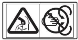
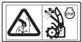
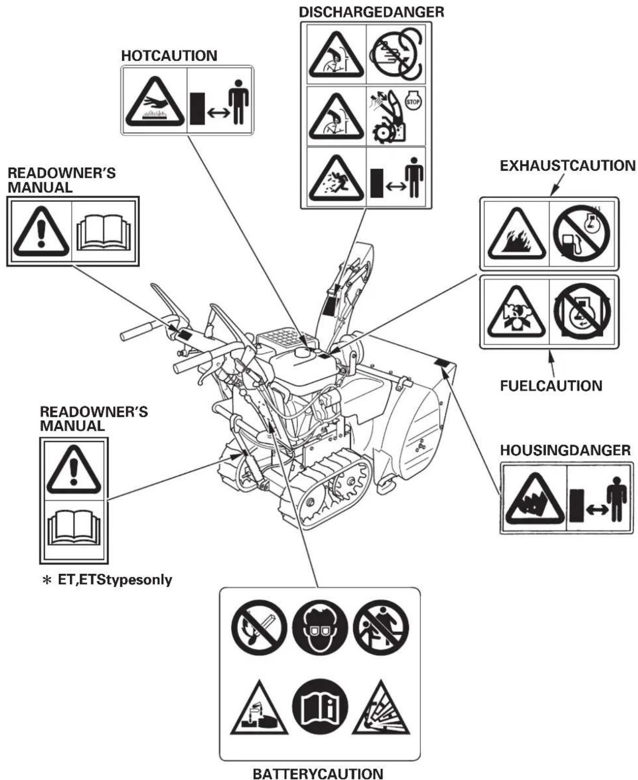
Theselabelswarnyouofpotentialhazardsthatcancauseseriousinjury.Readthelabelsandsafetynotesandprecautionsdescribedinthis manualcarefully.
Ifalabelcomesoffbecomeshardtoread,contactyourHondadealerforareplacement.
CEmarklocation
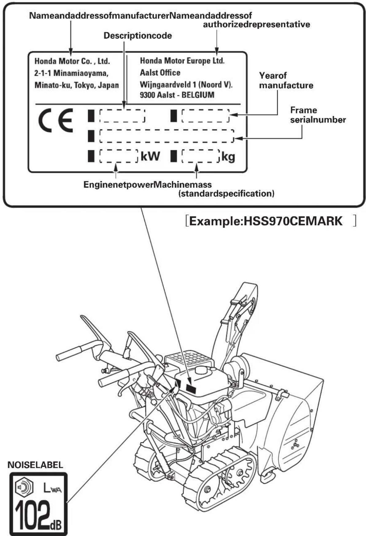
CEMARK
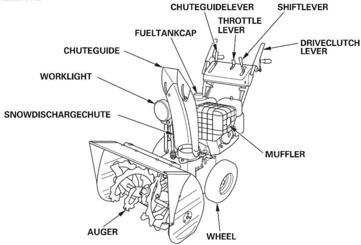
WHEELTYPE
* TheframeserialnumberisdescribedontheCEmarklabel(seepage 10).
* TheframeserialnumberisdescribedontheCEmarklabel(seepage 10).
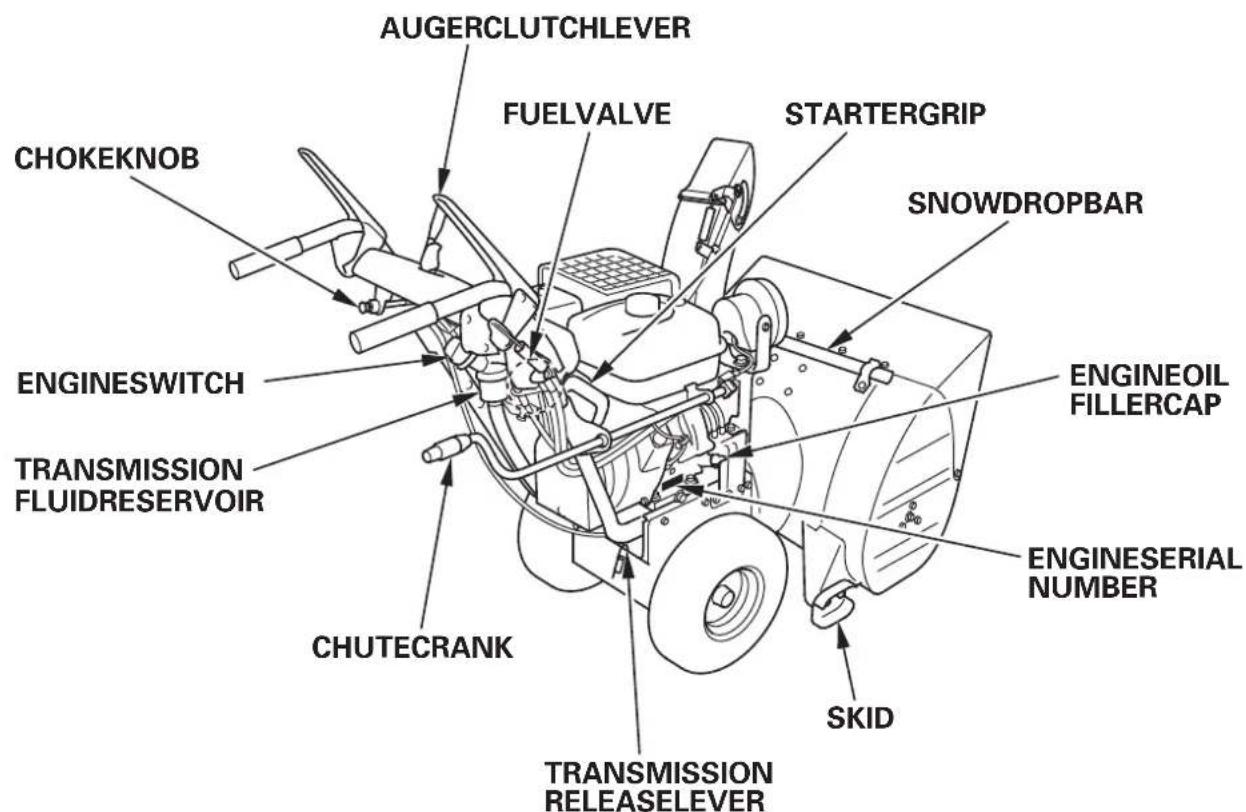
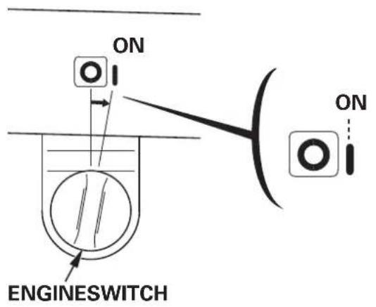
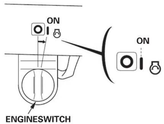
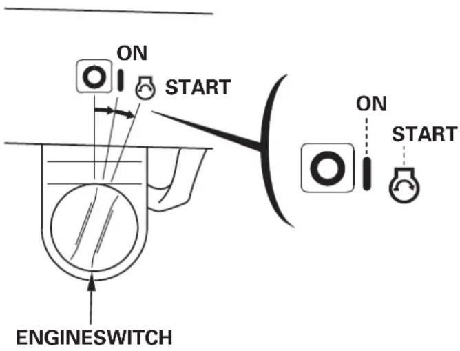
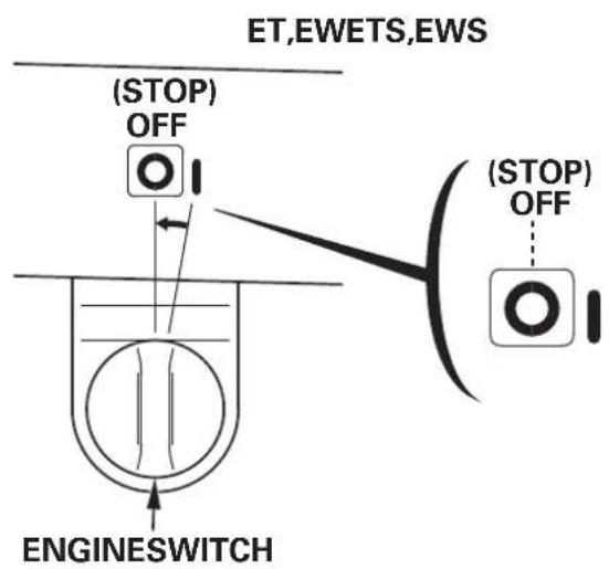
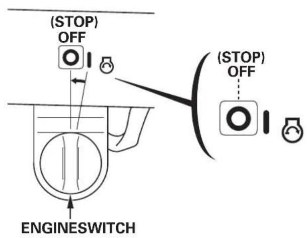
Engineswitch
Usetheengineswitchtoturntheignitionsystemonforstarting,and tostoptheengine.

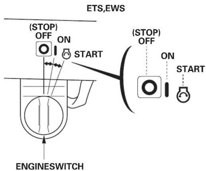
OFF....
Stopstheengine.Thekeycanonlybeinsertedandremovedwhen turnedtoOFF.
(ETS,EWS)
Theaccumulatedengineerunningtimeandauger-lockindicator.
ON....
Runningposition,andforstartingwiththerecoilstarter.
(ETS,EWS)
Theauger-lockindicatoronthehourmetercomeson,thenthe accumulatedenginerunningtimeisshown.
(ETS,EWS)
START....
Usethispositionontostarttheengineeringwiththeself-startsystem.The startingmotorwillrun.
Theswitchreturnstothe"ON"positionwhenyouletgoofthekey. Afterstartingtheengine,thedotofthehourmeterblinksandthe engineerrunningtimeisaccumulated.
Theauger-lockindicatorgoesoff.
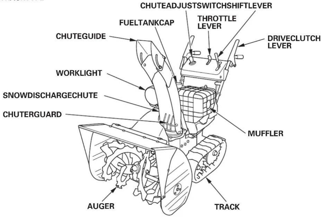
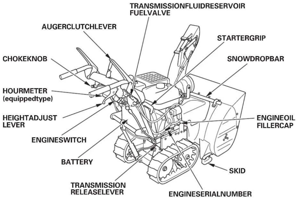
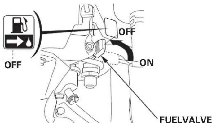
Fuelvalve
Thefuelvalveopensandclosesthefuellineleadingfromthefueltank tothecarburetor.Makesurethatthevalvespositionedexactly at eithertheONorOFFposition.
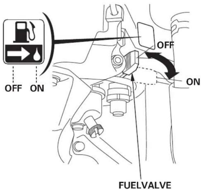
WARNING
Before transporting the nowblower, besuretoturnthefuelvalveto OFFtopreventpossiblefuelleaks; spilledfuelorfuelvapormayignite.
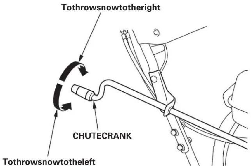
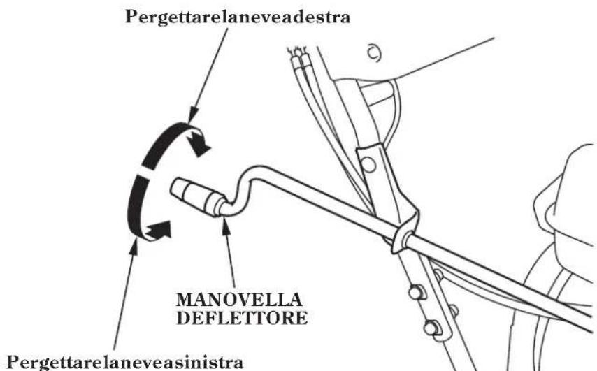
Chutecrank(ET,EW)
Usethechutecranktoturnthesnowdischargechuterightorleft.
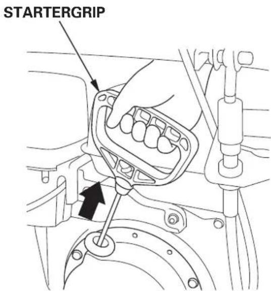
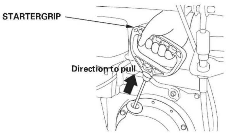
Startergrip
Pullingthestartergripoperatestherecoilstartortocranktheengine forstarting.
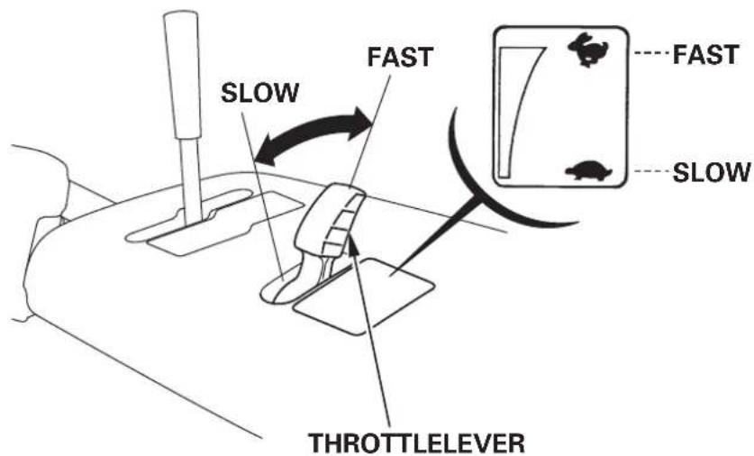
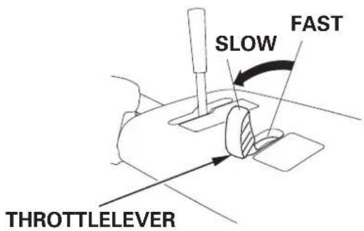
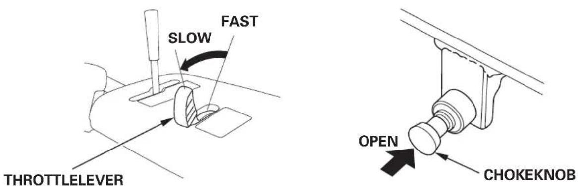
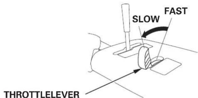
Throttlelever(enginespeed)
ThethrottleevercontrolsenginespeedfromSLOWtoFAST,itwill stayinanydesignatedposition.
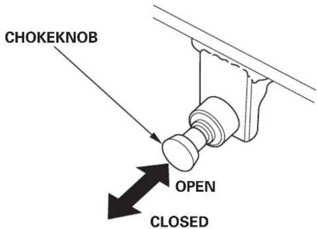
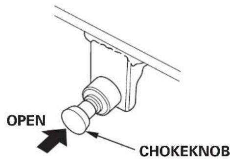
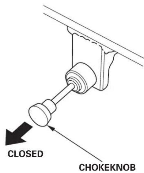
Chokeknob
Thechokeknobopensandclosesthechokevalveinthecarburetor.
TheCLOSEDpositionenrichesthefuelmixtureforstartingacold engine.
TheOPENpositionprovidesthecorrectfuelmixtureforoperation afterstarting, and forrestartingawarmengine.
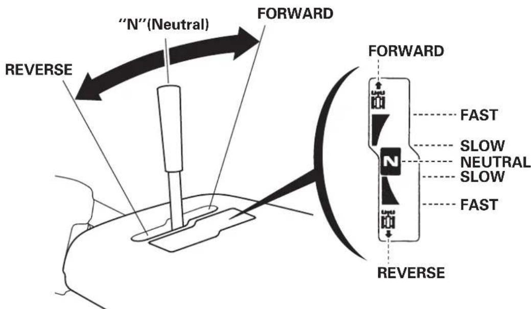
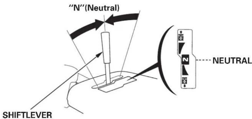
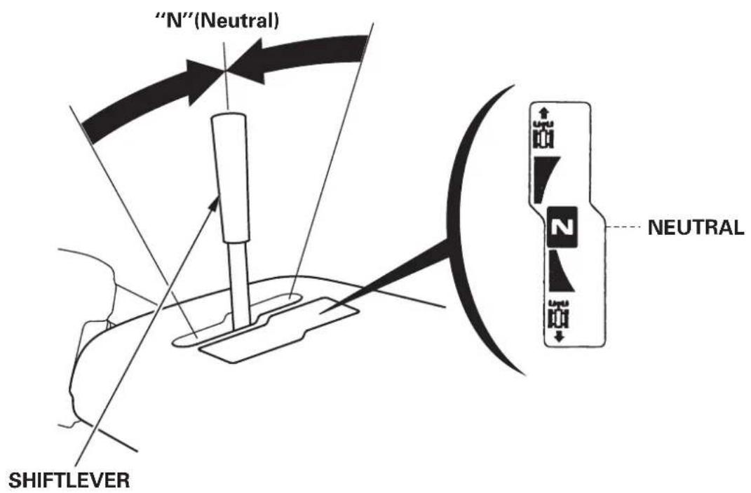
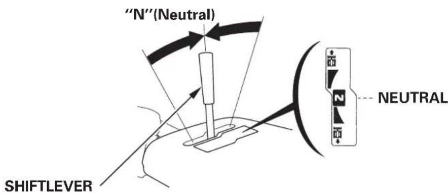
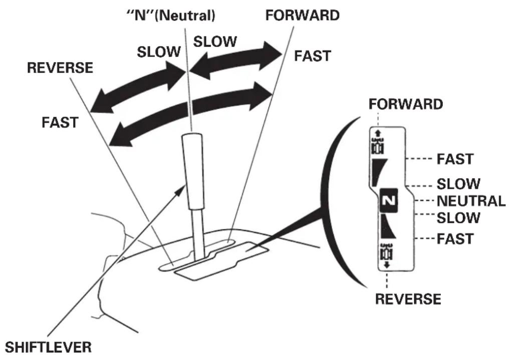
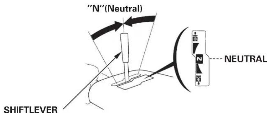
Shiftlever
Forwardandreversespeedscanbeselectedbyshiftingthislever;it willalsoremainanydesignatedposition.Settheleverin“N” (Neutral)whentheshnowblowerisnotused.
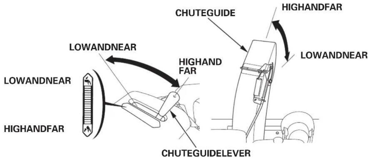
Chuteguidelever (ET,EW)
Thechuteguidecontrolsthesnowdischargeangleandddirection.
Chuteadjustswitch (ETS,EWS)
This switch is used to change the snow discharge angle or direction.
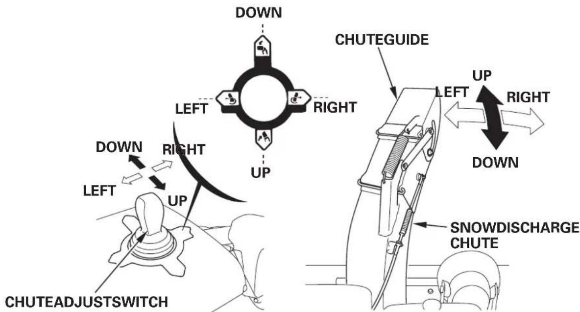
WARNING
Adjustthesnowdischargechutetoavoidhittingtheoperator, bystanders, windows, and other objects with ejected snow. Stay clear of the snow chuter while the engine is running.
NOTE:
Followthestepsinpageifthdischargechutecannotbeoperated electricallyduetoalowordeadbattery.
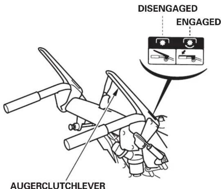
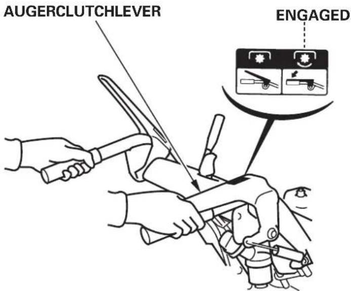
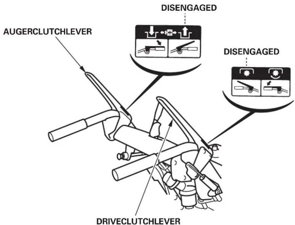
Augerclutchlever
Squeezingtheaugerclutchlever,thesnowthrowingmechanismstarts. Ifthedriveclutchleverissqueezed,thaugerclutchleverwillbefixed bysqueezingitonce.Bothoftheoperationisstoppedwhenreleasing thedriveclutchlever.
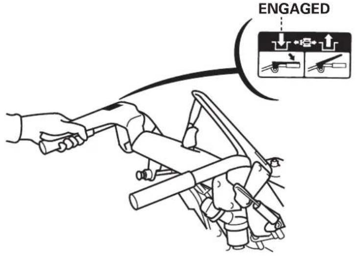
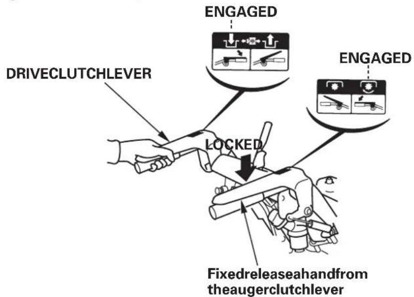
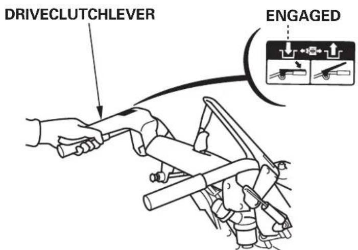
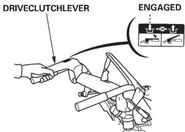
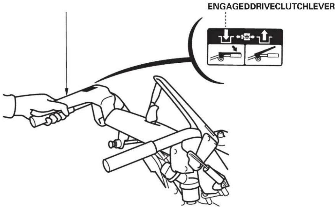
Driveclutchlever
Squeezingthedriveclutchlever,thesnowblowermoversforwardor backward.
lfthesnowbloweristransferred,squeezezethedriveclutchleveronly.
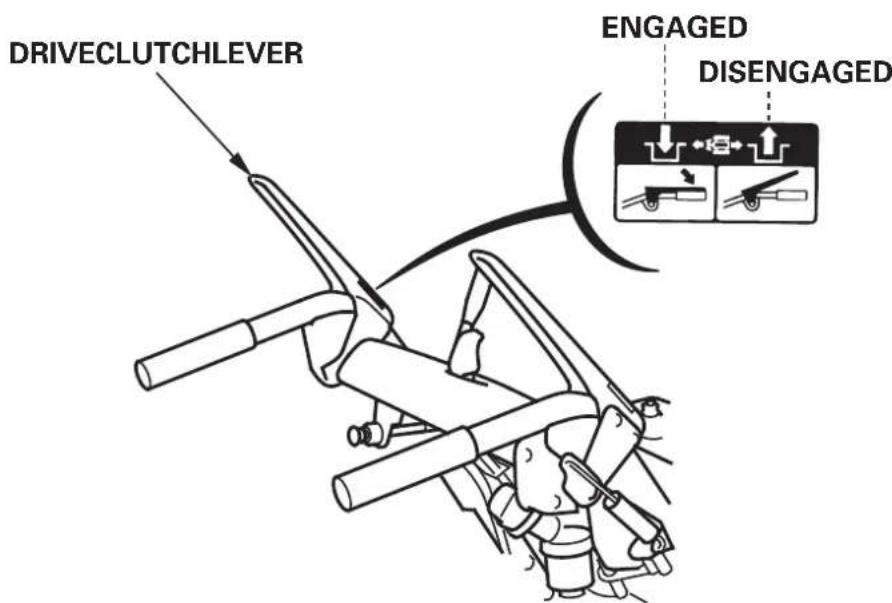
MOVINGONLY (Squeeze)
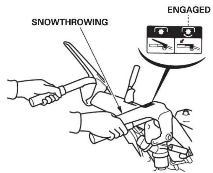
MOVINGANDSNOWTHROWING (Squeezetheaugerclutcheveronce)
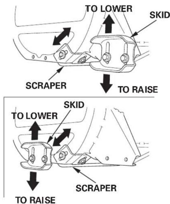
Skidandscaper
Adjusttheskidfortheaugerhousinggroundclearancebestsuitedto yoursnowremovalconditions.
Theskidcanbeinstalledattherearorsideoftheaugerhousing.
Theinitialpositionsetatthefactoryisrear.
Selecttheinstallationpositionforyourconvenience.
Removetheboltstouninstalltheskid,andthensettheskidto
conveniencepositionandtightentheboltssecurely.
WARNING
Topreventaccidentalstarting,turntheengineswitchtotheOFF positionanddisconnectthesparkplugcap.
- Placthesnowbloweronalevsurfacedsettheheightadjust leverinthemiddleposition(tracktypeonly).
- Movetheskidupordowntoobtainthedesiredaugerhousing groundclearance.
- Adjustthescapergroundclearanceto:
2.04.0mm(0.080.16in)
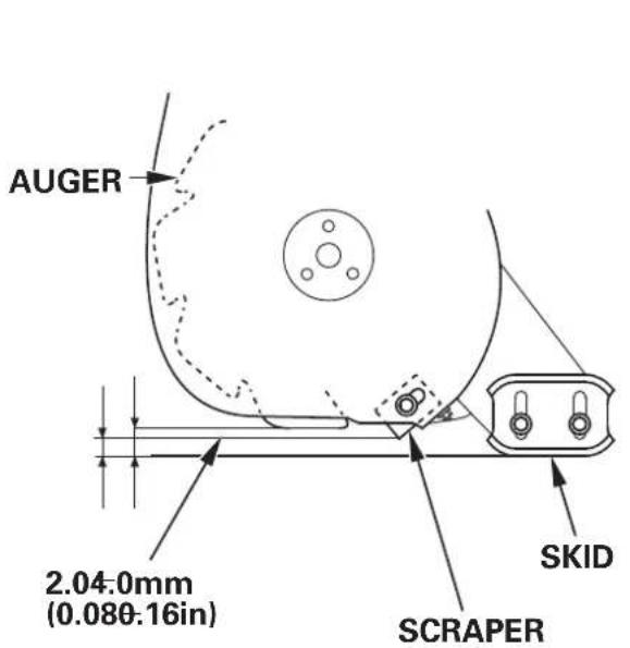
Forordinarysnow: 4.08-0mm(0.160.31in)
Forfinishing: 05.0mm(0.00.20in)
Foruseonunevensurfaces: 25.030.0mm(0.981.18in)
NOTE:
Adjusttheskidequallyonbothsides.
Besuretotightentheshkidandscaperboltssecurelyaftermaking adjustments.
CAUTION:
Donotusethesnowbloweronroughorunevensurfaceswiththe augergroundclearancesetforhardsnoworsurfaces.
Thismaycauseseriousdamagetothesnowblowingmechanism.
Factorypre-setclearance:
Atthescaper: 3.07-0mm(0.120.28in)
Attheauger: 8.012.0mm(0.310.47in)
Wearinspection
If the thickness of the skid contacting the ground surface is 0.5mm (0.02in), turntheskidupsidedown.
Replacetheskidifthethicknessislessthan0.5mm(0.02in)after turningtheskidupsidedown.
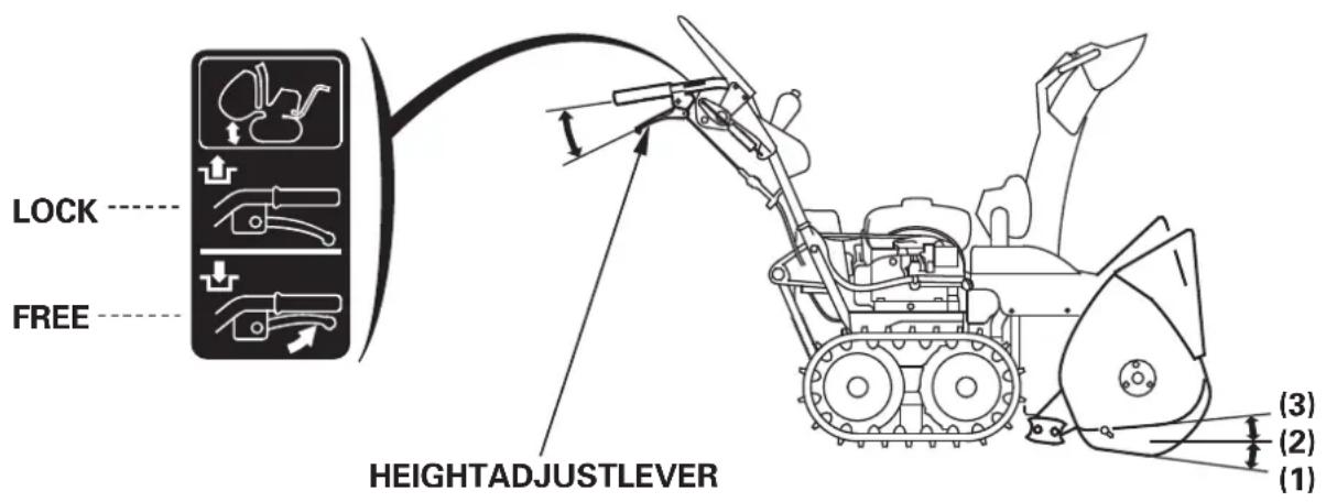
Heightadjustlever(tracktypeonly)
Usetheheightadjustleverwhenchangingtheheightofauger housing.
1) Hold the handle with both hands and squeezethe lever.
2) Movethehandleupanddowntoobtainthedesiredaugerposition.
3)Releasetheheightadjustlevertolocktheauger.
(1) LOW:Hardsnoworfinefinish
(2) MIDDLE:Normaluse
(3) HIGH:Deepsnoworfortransportingthesnowblower.
WARNING
- Donotdisassembleorthrowintofirethegasassisteddamper assemblyasitisfilledwiththehighpressuregas.Theassemblycan burst,causinginjury.
- Donotputyourhandonortiewitharope,oritmaycausea functionaldamageofthegasassisteddamperassembly.
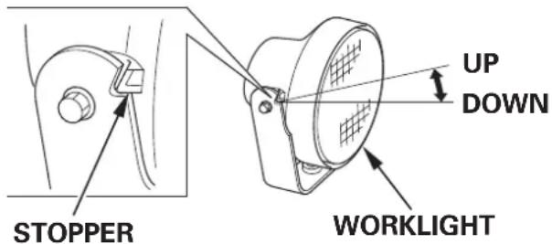
Worklight
ThelightcomesONwhiletheengineisrunning, anditgoesOFFwhen theenginestops. ThelightdoesncomeONwhentheengineswitch isturnedONunlesstheengineisstarted. Thelightcanbeadjustedup ordown.
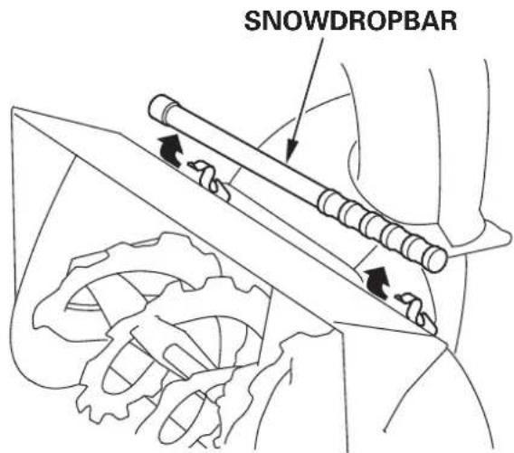
Snowdropbar
lfthesnowdischargechuteorsnowblowingmechanismbecomes clogged,stoptheengineandusethisbartounclogthem. Afterunclogging,wipethebarclean,andstoreitintheholders.
WARNING
Before removing clogged snow, besurestostoptheengine, and make sure that allrotatingpartshavecometoaccompletestop. Removethe sparkplugcapfromthesparkplug.
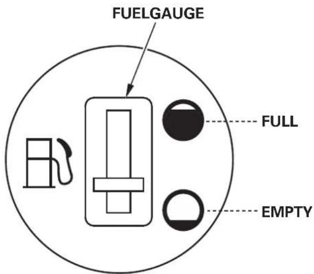
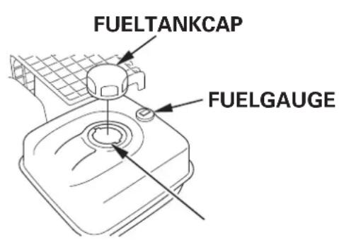
Fuelgauge
Thefuelgaugeindicates the amountoffuelin thetank. Whenthe fuel gaugeneedleentersthe EMPTY position, refill the tankkassoon as possible.
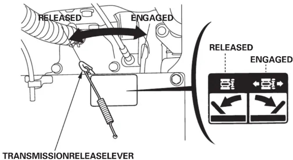
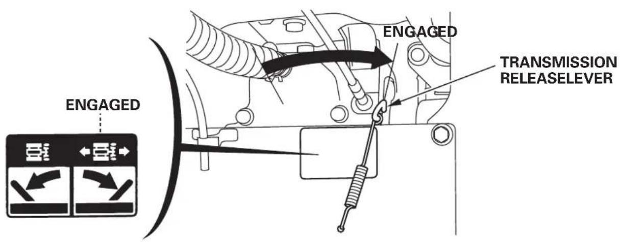
Transmissionreleaselever
The transmission releaseeverhastopositions,RELEASED and ENGAGED.SettheleverintheENGAGEDpositionwhenblowing snow;setittheRELEASEDwhenpushingthesnowblower.
WARNING
Nevershiftthetransmissionreleaseleveronslopes. Thesnow throwingmechanismmayoperatesuddenly, causingseriousinjuryor accident.
- Stoptheengine.
- Settheshiftleverinthe"N"(Neutral)position.
- SettleverintheENGAGEDorRELEASEDposition.
CAUTION:
Operatingthe transmission release leverwhile the engine is running, can damagethetransmission.
CAUTION:
Towingorpushingthesnowblowerwithanothervehiclewilldamage thetransmission.
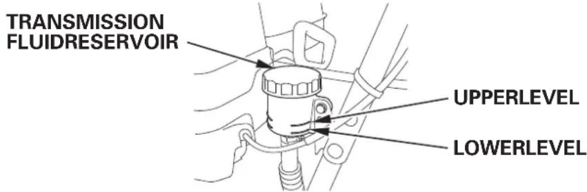
Hydrostatictransmissionfluid
Checkthehydrostaticfluidlevelinthereservoir.
Hydrostatic fluid expands sand contracts with changes in temperature.
TheUPPERandLOWERlevelmarksontheservoirarecalibratedfor roomtemperature fluid.
ItisnormalforthefluidleveltoriseabovevetheUPPERlevelmarkwhen snowbloweroperationwarmsthetransmission.
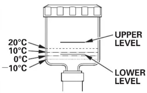
When checking the level of cold fluid, below room temperature, refer to the temperature chart for appropriate fluid levels.
Attemperaturesbelow 20^(4^) , fluid may not be visible in the reservoir before operation, but should rise into other reservoirs when the transmission warmsup.
If the fluid level is slow, add Honda Hydrostatic Fluid.
CAUTION:
The use of other hydrostatic fluids will reduce transmission performance and may damagethetransmission. UseonlyHonda HydrostaticFluid.
- Unscrewthereservoircapand removalseal.Becarefulto preventdirt,water,orsnowfromenteringthereservoir.
- Add Honda Hydrostatic Fluid to bring the fluid level to the UPPER levelmarkatroomtemperature,ortotheappropriatelevelshownin the temperaturechart.Donotoverfill.
- Reinstalltheseal, and tightenthecapsecurely.
| Temp. | Oillevel |
| 20°C | Betweenupperandlowerlevels |
| (68°F) | (approx.5mm(0.20in)abovelowerlevel) |
| 10°C | Slightlyabovelowerlevel |
| (50°F) | (approx.2mm(0.08in)abovelowerlevel) |
| 0°C | Slightlybelowlowerlevel |
| (32°F) | (approx.1mm(0.04in)belowlowerlevel) |
| -10°C | Betweenlowerlevelandbottomofoiltank |
| (14°F) | (approx.4mm(0.16in)belowlowerlevel) |
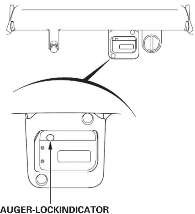
Auger-lockindicator(ETS,EWS)
Theauger-lockindicatorcomesonwhentheengineswitchisturnedto "ON"position,thengoesoffafterstartingtheengine.
Topreventtheaugerand/oraugermission,thesnowblowerstopsthe engineandblinkstheredauger-lockindicatorunderfollowing conditions:
- Foreignobject(FOREXample:stone)isincriminatedintherotating auger.
- Theaugercontactswithcurbstone.
Theaugerbreaksintohard-packedsnowforcibly.
Toremoveaforeignobject,followtheinstructionsshowninpage.
49
Whenstoppingtheengineduetoooverloadwhileplougingorlackof fuel, theauger-lockindicatorcomeson.
Inthiscase, removealoadorfillthefueltankwithgasolinetorestart theengine.
AUGER-LOCKINDICATOR
Topreventaccidentalstartingwhileremovingaforeignobjectfrom theauger,turntheengineswitchtothe"OFF"positionanddisconnect thesparkplugcap.
Makesurethataillrotatingpartsarestoppedcompletelybefore removingforeignobject.
Neverputyourhandintothesnowdischargechutewhiletheengineis running. Oritcanresultinseriouspersonaljury.
Hourmeter(ETS,EWS)
Thehourmetersshowstheaccumulatedenginerunningtimeofthe showblower.
Useitasaguidefortheinspectionnormaintenance.
When the engine switch is turn to "ON" position, the total accumulated engineerunningtimeisshown.
Afterstartingtheengine,thedotblinksandtheenginerunningtimeis startedtoaccumulate.
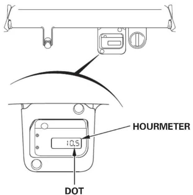
Fivedigitsareprovidedtoshowrunningtime,andtherightendddigit showsfirstdecimalplace.(1=6minutes)
Theenginerunningtimeindication goes off whenthe engine stops morethan 5 minutes with the engines switch positioned in "ON" position.
Therunningtimeindicationcomesonagainwhenrestartingthe engine.
Thebatterywilldischargeiftheengineswitchpositionedin"ON" positionwithoutengineerunning.
Checkthesnowbloweronlevelgroundwiththeengineeringstopped.
WARNING
Topreventaccidentalstart-up,removetheengineswitchkey,and disconnectthesparkplugcapbeforeperformingthepre-operation check.
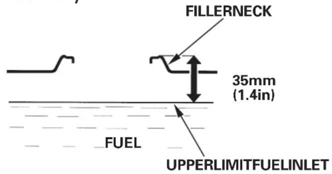
Fuellevel
Inspection:
CheckwhetherthefuelgaugeneedleisintheFULLposition.
Iftheneedleisnotintheposition,fillthefueltanktothevelshown.
Addfuelonlywhilestandingonthefueltanksideofthesnowblower.
UseunleadedgasolinewithaResearchOctaneNumberof91or
higher(aPumpOctaneNumberof86orhigher).
Neverusestaleorcontaminatedgasolineoranoil/gasolinemixture.
Avoidgettingdirtorwaterinthefueltank.
Afterrefueling,tightenthefueltankcapsecurely.
AWARNING
- Gasolineisextremelyflammableandisexplosiveundercertain conditions.
- Refuelinawell-ventilatedareawiththenginestopped. Donotsmokeorallowflamesorsparksintheareawherethe engineisrefueledorwheregasolineisstored.
- Donotoverfillthefueltank(thereshouldbenofuelinthefiller neck).Afterrefueling,makesurethefueltankcapisclosedproperly andsecurely.
- Becarefulnottospillfuelwhenrefueling.Spilledfuelorfuelvapor mayignite.Ifanyfuelisspilled,makesuretheareaisdrybefore startingtheengine.
- Avoidrepeatedorprolongedcontactwithskinorbreathing of vapor.KEEPOUTOFREACHOFCHILDREN.
NOTE:
Gasolinespoilsveryquicklydependingonfactorssuchaslight exposure,temperatureandtime.
Inworstcases, gasoline can be contaminated within 30 days.
Usingcontaminatedgasolinecanseriouslydamagethengine (cloggedcarburetor,stuckvalve).
Such damageduetospoiledfuelisdisallowedfromcoveragebythe warranty.
Toavoidthispleasestrictlyfollowtheserecommendations:
- Only usesspecifiedgasoline.
- Usefreshhandcleangasoline.
- Toslowdeterioration,keepgasolineinacertifiedfuelcontainer.
- Iflongstorage(morethan30days)isforeseen,drainfueltankand carburetor(seepage).69
CAUTION:
Don'tlet snow get in the fuel tank. Water in the fuelsystem can cause stalling and difficult starting.
GASOLINESCONTAININGALCOHOL
If you decide to use gasoline containing alcohol (gasohol), besureits octanerating is at leastashighasthat recommended by Honda.
Therearetwotypesof“gasohol”:onecontainingethanol,andthe othercontainingmethanol.
Donotusegasoholthatcontainsmorethan 10% ethanol.
Donotusegasolinecontainingmorethan 5 % methanol(methyl or woodalcohol)andthatdoesnalsocontainco-solventsand corrosioninhibitorsformethanol.
NOTE:
- Fuelsystemdamageorengineperformanceproblemsresulting from the use of gasoline that contains more alcohol than recommended isnotcoveredunderthewarranty.
- Before buying gasoline from an unfamiliar station, first determine if the gasoline contains alcohol, if it does, find out the type and percentage of alcohol used.
If you notice any undesirable operating symptoms while using a particular argasoline. Switch to gasolinethat you know contains less than there recommended amount of alcohol.
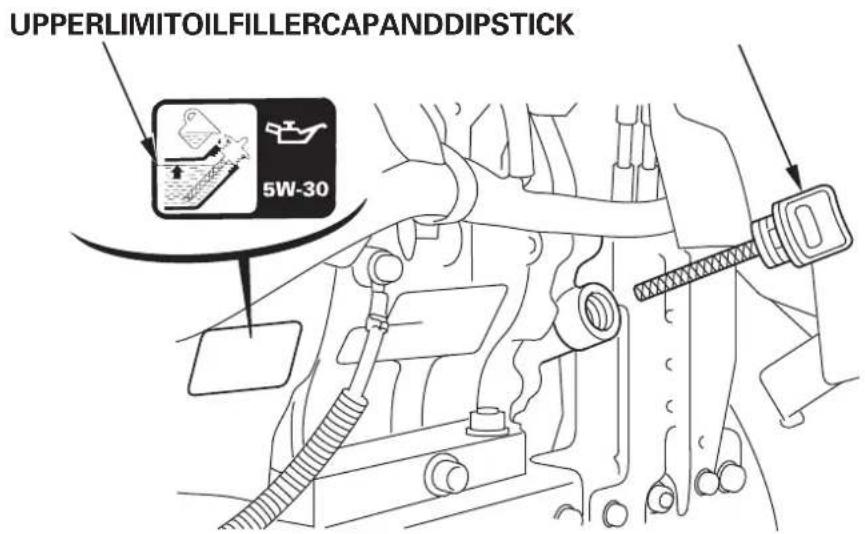
Engineoilevel
Inspection:
Withthesnowbloweronalevsurfacerovetheoilfillercapand wipethedipstickclean.
Insertthedipstickintothefillerneck, butdonotscrewitin. Remove the dipstick and checktheoillevel.
Ifthevelislow,filltotheupperlimitorthetopoftheoilfillerneck withtherecommendedoil.
Recommended oil
Use4-strokemotoroilthatmeetsorexceedstherequirementsforAPIserviceclassificationSEorlater(orequivalent).AlwayschecktheAPIservicelabelonteolcontainertobesureitcludesthelettersSEorlater(orequivalent).
SAE5W-30isrecommended for generaluse.
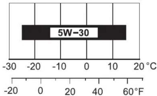
AMBIENTTEMPERATURE
QUANTITY SPECIFIED: 1.10L(1.16USqt,0.97Impqt)
CAUTION:
- Engineolisamajorfactoraffectingengineperformanceand servicelife. Nondetergentoilsand2-strokeengineeringolsarenot recommendedbecauseofinadequatelubricatingproperties.
- Runningtheenginewithinsufficientoilcancauseseriousenginedamage.
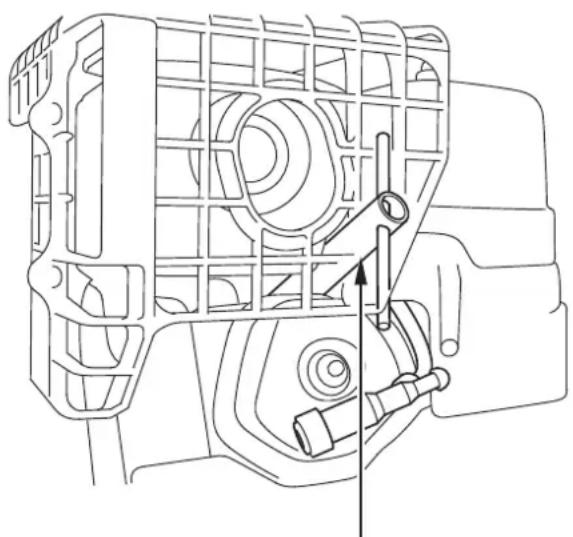
Batteryelectrolytelevel (ETS,EWS)
Inspection
Removethewowingnutsatthelowerportionofthebatterycover, thenremoveit.
Theelectrolytelevelmustbemaintainedbetweenheupperandlower levellinesonthesideofthebattery.
If the electrolyte levelslow, remove the battery from the snowblower and remove the battery filler caps, and carefully add distilled water to the upper levelling.
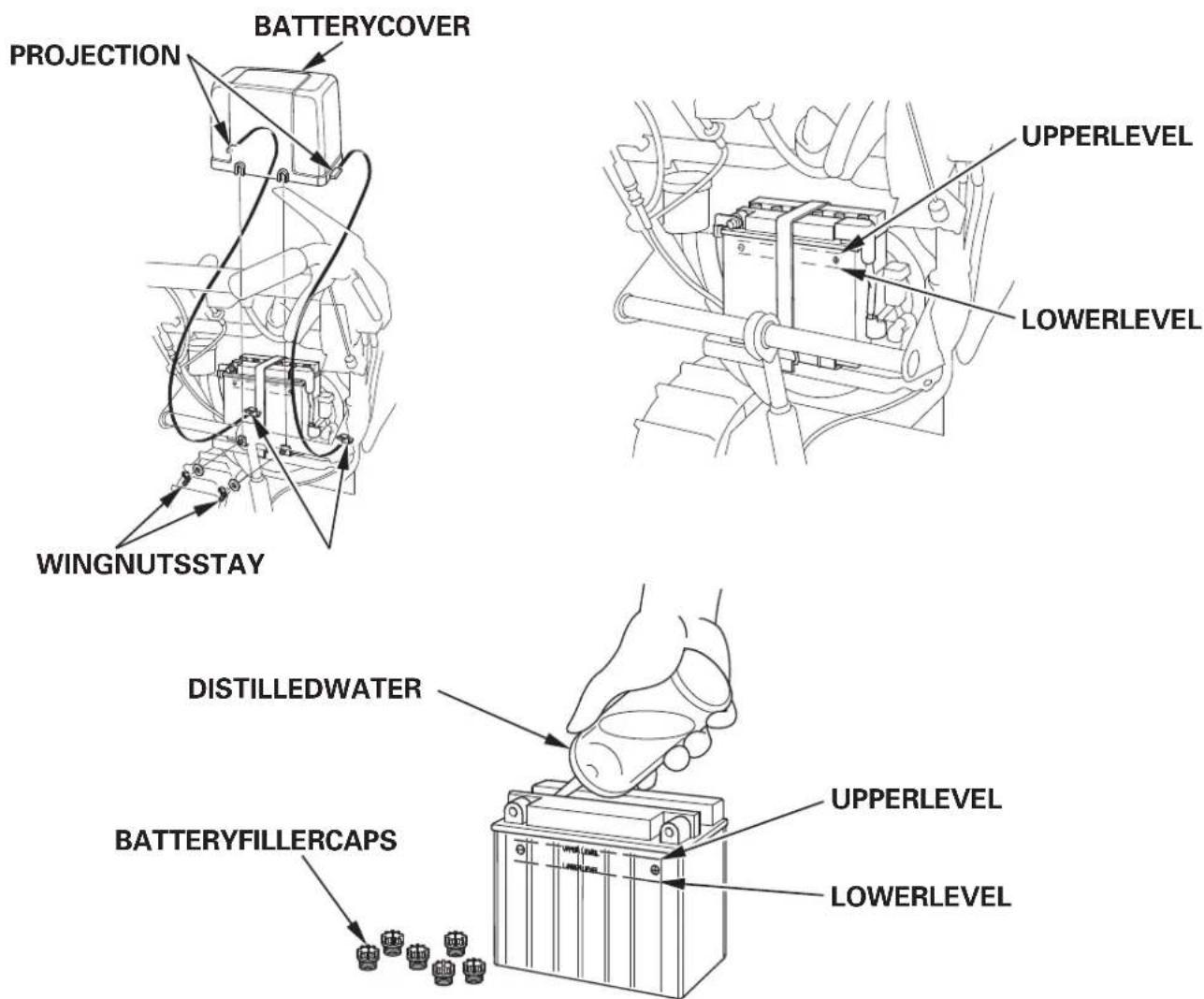
Forbatteryremovalandinstallation, follow the instructions shown in the page.71
Insert the projection of the battery cover into the stay, thentight the twowing nuts securely.
WARNING
- Thebatterygivesoffexplosivegases;keepsparks,flamesand cigarettesaway.Provideadequateventilationwhenchargingor usingbatteriesinanenclosedspace.
-
Thebatterycontainssulfuricacid(electrolyte).Contactwithskinoreyesmaycausesevereburns.Wearprotectiveclothingandafeshield.
-
Ifelectrolytegetsonyourskin,flushwithwater.
-
Ifelectrolytegetsinyoureyes,flushwithwaterforatleast15 minutesandcallaphysicianimmediately.
-
Electrolyteispoisonous.
-
Ifswallowed,drinklargequantitiesofwaterormilkandfollow withmilkofmagnesiaorvegetableoilandcallphysician.
- KEEPOUTOFREACHOFCHILDREN.
CAUTION:
- Useonlydistilledwaterinthebattery.Tapwaterwillshortentheservice life of the battery.
- DonotfillthebatterybeyondtheUPPERLEVEL.Ifoverfilled, electrolytemayoverflowandcorrodesnowblowercomponents. Immediatelywashoffanyspilledelectrolyte.
Augerandblowerbolts
Checktheaugerandblowerforlooseorbrokenbolts.lfbroken, replacethemwithnewones(seepage). 61
Otherchecks
- Checkallbolts, nutsandotherfastenersforsecurity.
- Checkeachpartforoperation.
- Checktheentiremachineforanyotherfaultswhichmighthave beencausedinthepreviousrunorwork.
WARNING
Neverruntheengineinanenclosedorconfinedarea.Exhaust containspoisonouscarbonmonoxidegas;exposurecancauselossof consciousnessandmayleadtodeath.
[Manualstarting]
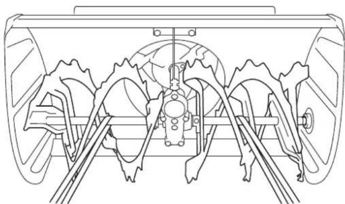
Movetheshiftleverto"N"(Neutral).1.
![Honda HSS1380A - [Manualstarting] - 1](/content/2026/02/414805/images/97d5b6080ce63326a8bc86a2efb20df911a7c5bec1539f7f391c63f2f77768ef.jpg)
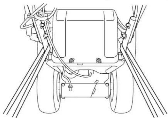
- SettletransmissionreleaseleverintheENGAGEDposition.
![Honda HSS1380A - [Manualstarting] - 2](/content/2026/02/414805/images/b346f9ff0f1d2ab32d6c4c33d671af075dae2ac92386f64aa96fb95f47826720.jpg)
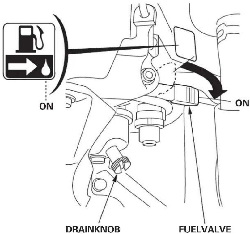
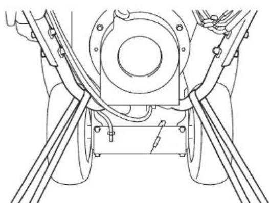
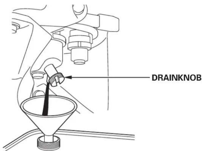
- TurnthefuelvalvetotheONposition. Besurethatthedrainknobistightenedsecurely.
![Honda HSS1380A - [Manualstarting] - 3](/content/2026/02/414805/images/c4c134796df5f4f7fc3b950d7ed3a48de286f2a1eac1c282f843877f462c4818.jpg)
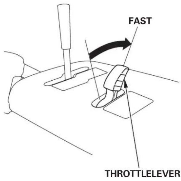
- Incoldweatherandwhentheengineiscold, pullthechokeknobto theCLOSEDpositionandmovethethrottleevertotheFAST position.
![Honda HSS1380A - [Manualstarting] - 4](/content/2026/02/414805/images/410ad45387fdd77815cd06362c9271df9b914e5e7ecb6d066781b5077ec1298a.jpg)
![Honda HSS1380A - [Manualstarting] - 5](/content/2026/02/414805/images/3318329c8147f460c4afa71d80868d8179a0920dc5c0cbfa13affdf4c5136dda.jpg)
- TurntheengineswitchtotheONposition.
(ETS,EWS)
Theauger-lockindicatoronthehourmetercomeson,thenthe accumulatedenginerunningtimeisshown.
ET,EWETS,EWS
- Pullthestartergriplightlyuntilyoufeelresistance,thenpullbriskly inthedirectionofthearrowasshownbelow.
CAUTION:
- Donotallowthestartergriptosnapbackagainsttheengine. Returnitgentlytopreventdamagetothestarter.
- Damagemayresultifthestartergripispulledwhiletheengineis running.
- Pullthestarterropetangentiallytowardthecontrolpanel.
(ETS,EWS)
Afterstartingtheengine, theotblinksandtheenginerunningtimeis startedtoaccumulate.
Atthisime, theauger-lockindicatorgoesoff.
- Lettheenginewarmupforseveralminutes.Then, follow the proceduresbelow.
If thechokeknobhasbeenpulledtotheCLOSEDpositiontostartthe engine,graduallypushittotheOPENpositionastheenginewarmsup. MovethrottleevertotheSLOWposition.
- Whilewarmingtheengineup,alsowarmthetransmissionas follows:
(1) Checkthattheshiftleverisinthe"N"(Neutral)position.
(2) Squeezehedriveclutchleverforabout30seconds.
[DClectricstarting(ETS,EWS)
- Movetheshiftleverto"N"(Neutral).
- SettletransmissionreleaseleverintheENGAGEDposition.
- TurnthefuelvalvetotheONposition. Besurethatthedrainknobistightenedsecurely.
- Incoldweatherandwhentheengineiscold, pullthechokeknobto theCLOSEDpositionandmovethethrottleevertotheFAST position.
- Turntheengineswitchto"START"positionandreleaseswitch aftertheengineisstarted.Theswitchautomaticallyreturnsto"ON" position.
Whentheengineswitchturnedto"ON"position, theauger-lock indicatoronthehourmetercomeson, the accumulated engine runningtimeisshown.
Afterstartingtheengine,thedotblinksandtheenginerunningtime isstartedtoaccumulate.
Atthisime, theauger-lockindicatorgoesoff.
WARNING
Neverholdors squeezetheaugeranddriveclutchleverswhen operating the starter motor; themachinewillstartsuddenlyasthe engine starts, resulting inaccidentorinjuly.
NOTE:
- Whenthespeedofthestartermotordropsafteraperiodofo time,itis anindicationthatthebatteryshouldberecharged.
-
Donotusethestartertermotorformorethan5seconds.lftheengine failstostart, releasethekey, and waitatleast10secondsbefore operating the startertermotor again.
-
After starting the engine, allow it to cool down and warm it up to operating temperature. As the engine stabilizes, gradually movethrough the SLOW position.
If thechokeknobhasbeenpulledtotheCLOSEDpositiontostart theengine,graduallypushittotheOPENpositionastheengine warmsup.MovethrottleevertotheSLOWposition.
- Whilewarmingtheengineup,alsowarmthetransmissionas follows:
Checkthattheshiftleverisinthe"N"(Neutral)position.(1)
(2) Squeezehedriveclutchleverforabout30seconds.
Highhaltitudeoperation
Athighaltitude, the standard carburetorair-fuel mixture will betoo rich. Performance will decrease, and fuel consumption will increase. A very rich mixture will also foul the sparkplug and cause hard starting.
Highaltitudeperformancecanbeimprovedbyspecificmodifications tothecarburetor.Ifyoualwaysoperateyoursnowbloweratalitudes above1,500meters(5,000feet),haveyourdealerperformthis carburetormodification.
Evenwithcarburetormodification,enginehorsepowerwilldecrease about 3.5% foreach300meter(1,000foot)increaseinaltitude.The effectofaltITUDEonhorsepowerwillbegreaterthanthisifnocarburetormodificationismade.
CAUTION:
Whenthecarburetorhasbeenmodifiedforhighaltitudeoperation, theair/fuelmixturewillbetooleanforlowaltitudeuse. Operationat altitudesbelow1,500meters(5,000feet)withamodifiedcarburetor maycausetheenginetooverheatandresultinseriousengine damage.Foruseatlowaltitudes,haveyourdealerreturnthe carburetortooriginalfactoryspecifications.
WARNING
Beforeoperatingsisequipmentyoushouldreadandunderstandthe SAFETYINSTRUCTIONSonpagethr@ugh. 8
- Starttheengineeringaccordingtotheproceduresdescribedinpage.
- MovethrottleevertotheFASTpositionfornormaloperation.
- Releasetheaugerclutchlever, and movetheshiftlevertoselectthe desireddrivespeed.
NOTE:
Lowspeededisrecommendedforremovingdeeporhard-packedsnow.
- Settheaugerhousingto"HIGH"position(Seepage). 22
-
Fixthethrowingdirectionbyusingthechutecrankandthechute guide.(Seepagesant17
-
Squeezeetheaugerclutchlever.
Themachinewillclearsnowwhenyousqueezezetheaugerclutch lever.
- Squeezehedriveclutchlever.
Bysqueezingthedriveclutchlever, theaugerclutchleverwill be fixed and you can operate without holding the auger clutch lever with yourrighthand.
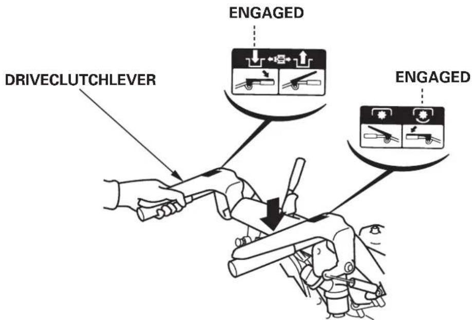
Whenbothleversaresqueezed,thedriveclutchleverlockstheauger clutcheverdown.Thisfreesyourrighthandtooperatetheother snowblowercontrols.Releasingthedriveclutchleverunlocksand releasestheaugerclutchlever.
Tomovefromoneplacetoanother,ortochangedirection,usethedriveclutchleveronly.Relaseboththedriveclutchleverandaugerclutchleveronce,thensqueezethedriveclutchlever.
Releasetheclutchlevertostopclearingormoving.8.
Clearingsnow
Forbestefficiency, clearsnowbeforeitmelts, refreezesandhards. Donotreduceenginespeedwhilethrowingsnow. Observethe followingtoclearhardordeepsnow.
Clearinginnarrowwidth
Clearsnowinslowspeedandinnarrowwidthbyusingpartofthe snowejectingmechanismwhentheshnowisdeeporhardens.
- Intermittentclearing
Followthestepsdescribedbelowwhentheenginelugsagainstdeep orheavysnow.
- MovetheaugerclutchlevertoSTOP.
- MovetheshiftlevertoNEUTRAL.
- Squeezeetheaugerclutchlevertorotatetheaugeronly.
- ReturntheaugerclutchlevertoSTOPaftertheengineeringpickup speed.
-
Movetheshiftlevertothedesiredposition,thensqueezetheauger clutchlever.
-
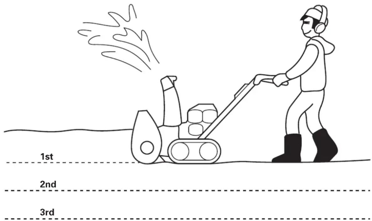
Clearingwithbackandforth motions
- Ifthesnowissohardthatthesnowblowertendstorideoverthesurface, pushitbackandforthremovesnowgradually.
- Clearing insteps Iftheheightofthesnowisgreaterthantheheightofthesnow-throwingmechanism,removeitseveralstepsasshown.
WARNING
- Adjustthesnowdischargechutetoavoidhittingtheoperator, bystanders, windows, and other objects with throw snow. Stay clear of the snow discharge chutewhile the engine is running.
- Ifthesnowdischargechutebecomesclogged,stoptheengine and useasnowdropbarorawoodensticktounclogit. Neverputyourhandintothesnowdischargechutewhile the engineisrunning;seriouspersonalinjurycouldresult.
- Tomovefromoneplacetoanother,ortochangedirection,usethe driveclutchlever.Usingtheaugerclutchleverwillcausethesnow blowingmechanismtorotate,possiblyresultinginequipment damageorpersonalinjury.
CAUTION:
- Nevermovetheshiftleverwhilethesnowblowerisinmotion. Besuretodisengagethedriveclutchoraugerclutchbforeshifting gears.
If you need to have the weather, take your snow blower to an authorized Hondadealer.
(ETS,EWS)
Iftheauger-lockindicatorblinksandtheenginestops.
Iftheenginestopsandredauger-lockindicatorblinks,following symptommayoccur.
- Aforeignobject(FOREXample:stone)isincriminatedintherotating auger.
- Theaugercontactswithcurbstone.
- Theaugerbreaksintohard-packedsnowforcibly.
Followtheinstructiondescribedbelowremoveaforeignobject.
Topreventaccidentalstartingwhileremovingaforeignobjectfrom theauger,turntheengineswitchtothe"OFF"positionanddisconnect thesparkplugcap.
Makesurethatallrotatingpartsarestoppedcompletelybefore removingforeignobject.
Neverputyourhandintothesnowdischargechutewhiletheengineis running. Oritcanresultinseriouspersonaljury.
- Turntheengineswitchtothe"OFF"position.
- Disconnectthesparkplugcap.
- Makesurethatallrotatingpartsarestoppedcompletely.
- Ifnecessary,removethesnoworforeignobjectfromtheauger.
Ifremovalisdificultduetoobjectincrimination,rotatetheaugerinthereversedirectionforeasyremoval.
- Connectthesparkplugcapsecurely.
6.Starttheengine. - Squeezethesnowdischargeclutchleverandrotatetheauger,then makesurethattheauger-lockindicatorremainsoff.
-
Squeezezethedriveclutchleveranddonormalsnowdischarging.
-
Thesystemisinabnormalcondition,whentheauger-lockindicator blinkseveniftheenginestoppingduetoobjectincriminationor othersimilarcauseisnotdone,whilesnowdischarging. Inthiscase,turntheengineswitchto"OFF"position,pulloutthe keyandconsultyourdealer.
- Theauger-lockindicatorremainsonwhentheengineswitchisnot turnedto"OFF"positionandtheenginestartedagainevenifan objectisremoved. Inthiscase, turntheengineswitchto"OFF"position, then start the engine again.
- Thebatterycapacitymaybelowedwhenthetroubleisnotfound intheaugerandengineisstopped. Inthiscase, charge the battery (page) or replace it.
- Thesystemisinabnormalcondition,iftheauger-lockindicator blinkswithensqueezingthesnowdischargeclutchlever,after removinganobjectandstartingtheengineagain. Inthiscase,turntheengineswitchto"OFF"position,pulloutthe keyandconsultyourdealer.
ToSTOPtheengineeringemergency,turntheengineswitchOFF immediately.
(ETS,EWS)
The accumulated enginerunningtimeandauger-lockindicatoronth hourmetergooff.
Torestarttheengine, movetheshiftleverbacktothe "N"(Neutral) position.
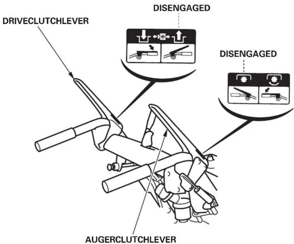
1. Releasetheaugeranddriveclutchlevers.
Themachineandsnowblowingmechanismwillstopoperation.
- Movetheshiftleverto"N"(Neutral).
- MovethrottleevertothesLOWposition.
- TurntheengineswitchtotheOFFposition.
(ETS,EWS)
Theaccumulatedenginerunningtimeandauger-lockindicatoronthhourmetergooff.
- TurnthefuelvalvetotheOFFposition.
CAUTION: Donotparkthesnowbloweronaslopeasitisnotequippedwith parkingbrakemechanism.
Periodic inspection and maintenance will help extend the servicelife of yoursnowblower while keeping it in the best operating condition. Inspectorserviceasdescribedinthetablebelow.
AWARNING
- Shutofftheenginebeforeperforminginspectionandmaintenance, anddisconnectthesparkplugwirefromtheplugsotheengine cannotstarted.
- Iftheenginemustberun,makesuretheareaiswell-ventilated. Exhaustgascontainspoisonouscarbonmonoxide;exposurecan causelossofconsciousnessandmayleadtodeath.
CAUTION:
- Toavoid overturning,placthesnowbloweronalevsurfabebeforeperforminginspectionandmaintenance.
- UseonlygenuineHondapartsortheirequivalent. Replacementpartswhicharenotofequivalentqualitymaydamage thesnowblower.
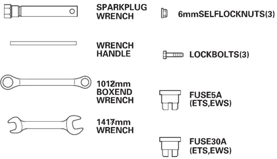
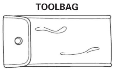
Tools
Asparkplugwrenchandhandlearesuppliedwiththesnowblower. Someofthemaintenanceproceduresdescribedinthismanualwill requireasetofmetricwrenches(notsupplied).

Maintenanceschedule
| REGULARSERVICEPERIOD(1)Everymonthoperatinghourinterval,whichevercomesfirst.Item | EachusePerfBeataveoperation | Everyyear | Firsttendthor20hrs. | 100hrs. | Every300hrs. | Every4years | ||
| Engineoil | Checklevel | ○ | ||||||
| Change | ○(4) | ○ | ○(4) | |||||
| Augermissionoil | Checklevel | ○(2) | ||||||
| Transmission | Grease | ○(2)(4) | ||||||
| (TrackTypeonly) | ||||||||
| HSToil | Checklevel | ○ | ||||||
| Battery | Checklevel | ○ | ||||||
| electrolyte | Checklevel | ○(2)(4) | ||||||
| (Ifapplicable) | andgravity | |||||||
| Sparkplug | Check-adjust | ○(4) | ||||||
| Replace | ○ | ○ | ||||||
| Augerskidshoes | Check-adjust | ○ | ○(4) | |||||
| andscaper | ||||||||
| Track | Check-adjust | ○(4) | ○ | |||||
| Wheel | Check | ○ | ○ | |||||
| Augerandblowerlockbolt | Checklockbolt | ○ | ||||||
| Bolts,nuts,fasteners | Checkfasteners | ○ | ||||||
(1) For professional commercial use, loghoursof operationtodeterminepropermaintenance intervals.
(2) TheseitemssshouldbeservicedbyyourHondaservicingdealer,unlessyouhaven the propertoolsandaremechanicallyproficient.RefertotheHondaShopManualforservice procedures.
(3) Checkthebeltforwearordamage.Replacethebeltwithanewoneifitiswornordamaged.
(4) Thesepartsmayrequiremorefrequentinspectionandreplacementunderheavyuse.
| REGULARSERVICEPERIOD(1)First monthoperatinghour interval,whichevercomes first. Item | Each usePerfBeataveoperation | Everyyear | Month or 20hrs. | Every 100hrs. | Every 300hrs. | Every 4years | ||
| Fulsediment cup | ○ | |||||||
| Fueltankand carburetor | ○ | |||||||
| Anticorrosion oil | ○ | |||||||
| Chuteguide contro cable | ○(2)(4) | ○(2)(4) | ||||||
| Augerclutch cable | ○(2)(4) | ○(2)(4) | ||||||
| Throttle/Choke cable | ○(2)(4) | |||||||
| Driveclutch cable | ○(2)(4) | ○(2)(4) | ||||||
| Augerhousing adjustlever | ○(2)(4) | |||||||
| Drivebelt | ○(2)(3)(4) | ○(2)(3)(4) | ||||||
| Augerbelt | ○(2)(3)(4) | ○(2)(3)(4) | ||||||
| Idlespeed | ○(2) | ○(2) | ||||||
| Valveclearance | ○(2) | ○(2) | ||||||
| Combustion chamber | Afterevery1,000hrs.(2) | |||||||
| Fueltankand filter | ○(2) | ○(2) | ||||||
| Fueltube | Clean | Every2years(2) | ||||||
| Replace | ○(2) | |||||||
(1) For professional commercial use, loghoursof operationtodeterminepropermaintenance intervals.
(2) TheseitemssshouldbeservicedbyyourHondaservicingdealer,unlessyouhaven the propertoolsandaremechanicallyproficient.RefertotheHondaShopManualforservice procedures.
(3) Checkthebeltforwearordamage.Replacethebeltwithanewoneifitiswornordamaged.
(4) Thesepartsmayrequiremorefrequentinspectionandreplacementunderheavyuse.
Engineoilchange
Iftheengineoilisdirty,enginewearwillocurmorerapidly.Chang theoilatdesignatedintervals.Maintaintheoilattheproperlevel.
OILCHANGEINTERVAL:Firstmonthor20hrs.,oreveryyear,before operation.
RECOMMENDEDOIL: Use5W-304-strokemotoroilthatmeetsor exceedstherequirementsforAPIservice classificationSEorlater(orequivalent). AlwayschecktheAPIservicelabelonteol containertobesureitincludesthelettersSEor later(orequivalent).
QUANTITYSPECIFIED:1.10L(1.16USqt,0.97Impqt)
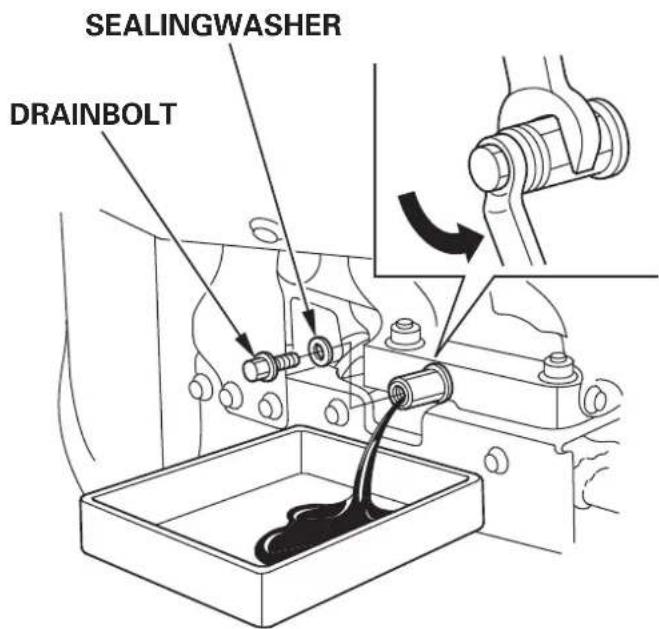
Howtochangetheoil:
- Placthesnowbloweronalevssurface.
- Removethengine oilfillercap,drainbolt,andsealingwasher. Draintheoilwhilethengineisstillwarmtoassurerapidand completedtraining.
- Installanewsealingwasheranddrainboltandtightenthe bolt securely.
CAUTION: If youdnaintheoilimmediatelyafterstoppingtheengine,its temperaturewillbehighandmaycauseburns.
- Fillwithnewoil(seepage) totheupperlimit,asindicated by theoilfillergauge.(Incheckingtheoillevelwiththeoilfillergauge, donotscrewthegaugein.)
- Afterreplacingtheoil,securelytightenthengine oilfillercap.
Washyourhandswithsoapandwaterafterhandlingusedoil.
NOTE:
Pleasedisposeofusedmotoroilinamannerthatiscompatiblewith theenvironment.Wesuggestyoutakeitinasealedcontainertoyour localservicestationforrecycling.Donotthrowinthetrashorpourit ontotheground.
Sparkplugcheckingandadjustment
Thesparkplugmustbeperiodicallycheckedandadjustedtoprovide reliableignition.
INTERVALATWHICHTHESPARKPLUGMUSTBECHECKED:
Everyyear, before operation.
CLEANINGPROCEDURE:
WARNING
Iftheenginehasbeenrunning,themufflerwillbeveryhot.Becareful nottotouchthemufflerwhileitishot.
Toensureproperengineoperation,thesparkplugmustbeproperly gappedandfreeofdeposits.
- Removethesparkplugcap.
- Cleananydirtfromaroundthesparkplugbase.
- Usethewrenchsuppliedinthetoolkittoremovethesparkplug.
- Inspectthesparkplug.Replaceitiftheelectrodesarewornorifthe insulatoriscrackedorchipped.lfitistobereused,cleanthe electrodeandinsulatorwithawirebrush.
SPARKPLUGWRENCH
- Measurethepluggapwithafeelergauge.
Correctasnecessarybycarefullybendingthesideelectrode.
Thegapshouldbe:
0.70.8mm(0.0280.031in)
STANDARDPLUG:BPR5ES(NGK)
W16EPR-U(DENSO)
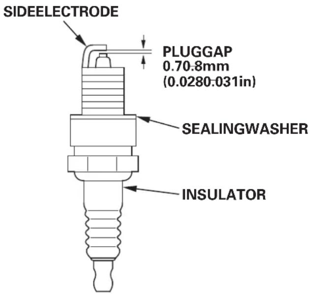
- Makesurethatthesparkplugsealingwasherisingoodcondition andthreadthesparkpluginbyhandtopreventcross-threading.
- Afterthesparkplugisseated,tightenwithasparkplugwrenchto compressstewasher.
NOTE:
linstallangewesparkplug,tighten1/2turnafterthesparkplugseats tocompresssthewasher.lfreinstallingausedsparkplug,tighten1/8to 1/4turnafterthesparkplugseats.
CAUTION:
- Useonlytherecommendedsparkplugsarequivalentplugs.Spark plugswhichhaveanimproperheatrangemaycauseengine damage.
- Thesparkplugmustbesecurelytightened.Animproperly tightenedsparkplugcanbecomeeveryhotandmaydamagethe engine.
Track-adjustment(tracktypeonly)
ADJUSTMENTINTERVAL:Everyyear,beforeoperation
Makesurethetracksarecleananddrybeforeadjustment. Thetracks cannotbecorrectlyadjustedifcloggedwithsnowordebris,orcoated withice.
Withthesnowblowerrestingon itstracks,checktrackdeflection by pressing down midway betweenthewheelswithaforce of15kgf(33lbf).
Whencorrectlyadjusted,track deflectionsshouldbe: 27.0-33.0mm(1.06 -1.30in)
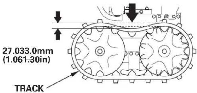
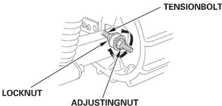
Adjustingprocedure:
- Loosentheleftandrighttensionboltlocknutsattherearaxle,and turntheadjustingnutstocorrectlytensionbothtracks.
- Afteradjustment,tightenthalocknutssecurely.
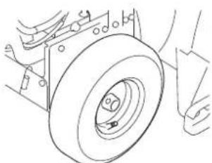
Tires(wheeltypeonly)
CAUTION:
- Donotoperatewithaflattire. This may cause thebeadtocomeoff.
- Overinflationcancauseprematuretirefailure.Inflatethetirestomanufacturer'srecommendedtirepressure.
Before each use, check the tire pressure with an air pressure gauge.
Pressure: 55kPa(0.55kgf/cm,8².0psi)
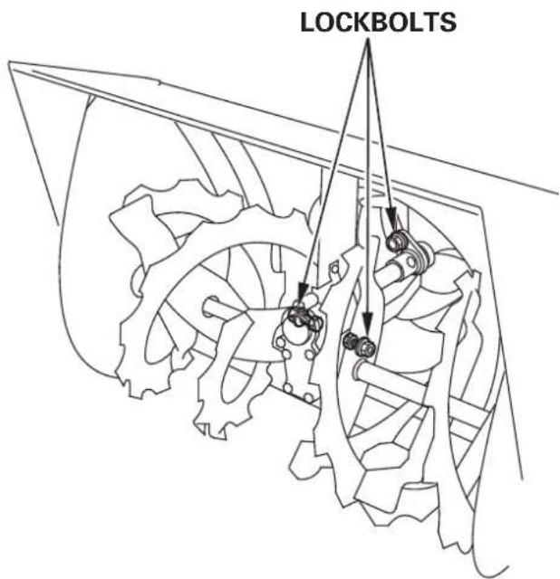
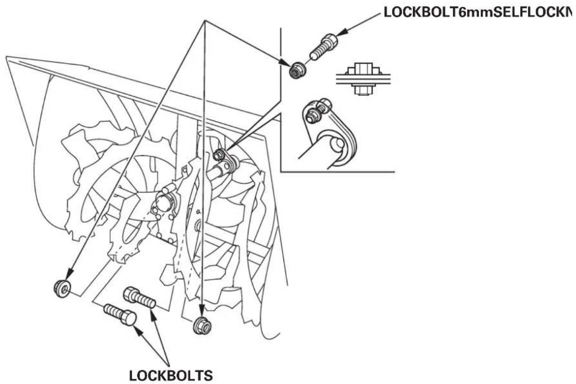
Auger/Blowerinspection
Checktheauger,augerhousing,blower,andlockboltsforsignsof damageorotherfaults.Ifanyofthelockboltsisbroken,replaces them withtheonefurnishedwiththesnowblower.Additionalallockboltsand nutsareavailablefromauthorizedHondasnowblowerdealers.
CAUTION:
Lockboltsaredesignedtobreakunderforcethatwouldotherwise damageaugerandblowerparts.Donotreplacelockboltswith ordinaryhardwarebolts.
Lockboltreplacement procedure
- Placethesnowbloweronafirm.levelsurface.
- TurntheengineswitchOFFandremovethecapsfromthespark plugs. Checkthatallrotatingpartshavebeenbroughttoacomplete stop.
- Cleantheaugerandblowerofsnow, ice, oranyotherforeign particles.
- Checktheentiresnowclearingmechanism.
- Replaceanybrokenlockbolts.Tightensecurely.
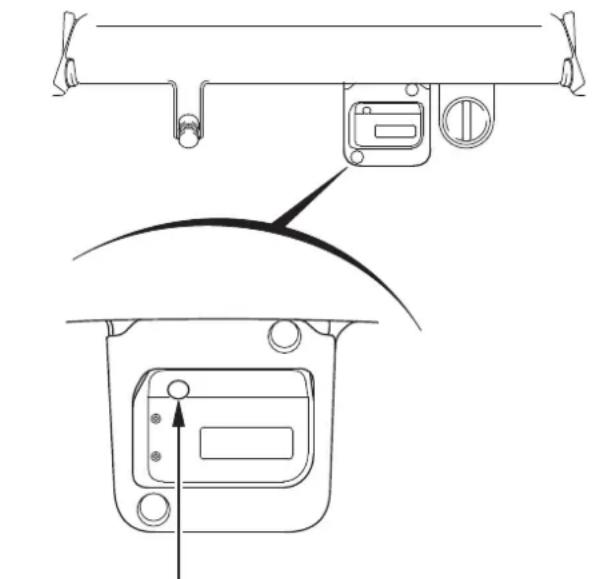
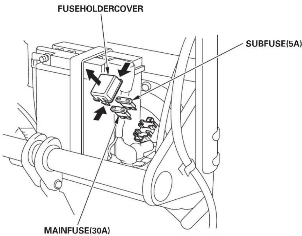
Fuse(ETS,EWS)
If the fuse is blown, the starter motor won't operate.
Intheeventofblowerfuse,replaceitwithanotherfuseoftherated capacityonlyafterinvestigatingthecauseforthefailure.lfthefuseis replacedwithoutcorrectingcause,thenewfusemayblowquickly again.
CAUTION: Neverreplaceablownfusewithanyobjectotherthananotherfuseof theratedcapacity.Usinganyotherobjectsuchaswireoraluminum foilmaycausefiresinwiringorotherparts.
Fuse-replacement
- TurntheengineswitchtotheOFFpositionandremovethekey beforecheckingorreplacingthefuse.
- Removethebatterycover(seepage). 32
- Removethefuseholdercoverandpullthefuseout.
- Replace the use with a use of the same type and rating.
Specifieduse: 5 A,30 A
CAUTION:
- Iffrequentfusefailureoccurs,determine the cause and correct the problem before attempting to operate the snowblower further.
-
Neveruseafusewithadifferentratingfromthatspecified.Serious damagetothecilectricalsystemormiremayresult.
-
Installthefuseholdercover.
6.32stallthebatterycover(seepage).
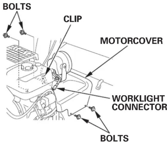
SnowdischargechuteManualadjustment (ETS,EWS)
Intheeventthatthesnowdischargechutecannotbeoperated electrically, openthebatterycoverandcheckforbrownfuse. If the fuseisnotbrown, adjustthesnowdischargeangleanddistance as follows:
Dischargeangleadjustment:
- Checkthattheengineswitchisin theOFFposition.
- Removethefourboltssecuring themotorcover. Disconnect the worklight connector. Loosentheboltsecuringthework lightandremovetheclip,then removethemotorcover.
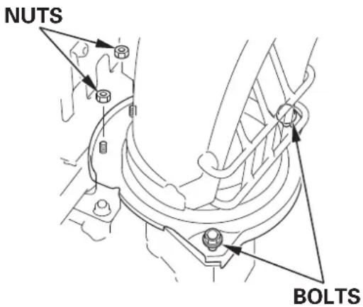
- Removethetwonuts.
- Loosentheboltsthatfastenthe chuttersetplates.
- Raisethe dischargechuteenough tobringthechutergearoutof engagementwiththemotorgear.
- Set the discharge chute at the desiredangle.
- Retightenthechuttersetplate bolts.
- Tightenthetwonuts.
- Reinstallthemotorcover.
- Reinstalltheclipandretightenthe work light bolt. Connect the work lightconnector.

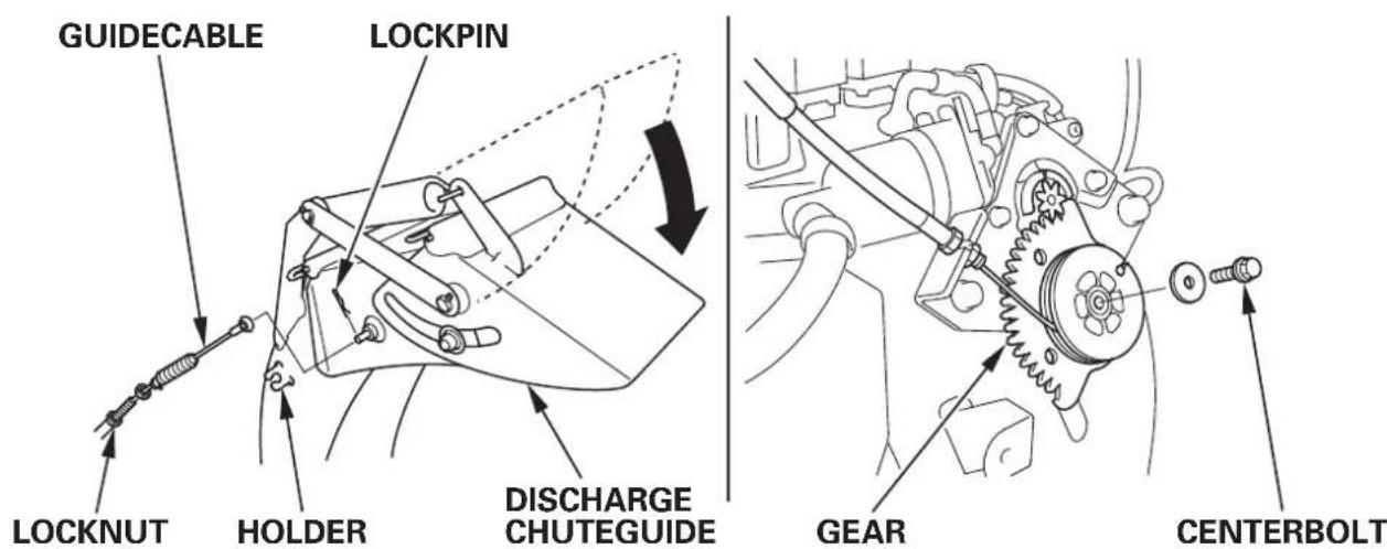
DischargedistanceadjustmentManualadjustment (ETS,EWS)
- Removethemotorcover(seepage). 64
- Removethelockpin. Loosenthelocknutandremovetheguidecablefromtheholder. Removethegearbyremovingthecenterbolt.
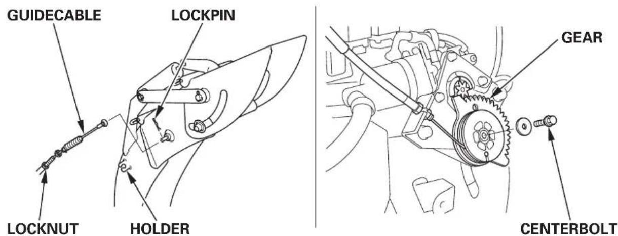
- Holdthedischargechuteguidesothatispositionedlowest,install thegearasshown.
- Install the guide cable and lock pin in thereverse order of removal. Tighten the lock nut securely.
- Reinstallthemotorcover(seepage). 64
NOTE:
Haveyoursnowblowerinspectedandrepairdebyourauthorized Hondadealerassoonasyoucompletethesnowremovaloperation.
Beforeloading
- Loadingthesnowbloweronatrailersshouldbeperformedonafirm, levelsurface.
- Usealoadingrampthatisstrongenoughtosupportthecombined weightofthesnowblowerandtheoperator:
Weightofsnowblower:Operatingweight
| HSS970HSS13 | 80 |
| 115kg(254lbs) | 130kg(287lbs) |
| : ET | : ET |
| 125kg(276lbs) | 140kg(309lbs) |
| :ETS | :ETS |
| 105kg(231lbs) | |
| : EW | |
| 120kg(265lbs) | |
| : EWS |
- Theloadingrampmustbelongenoughsothatitsslopeis 15^(26%) orless:
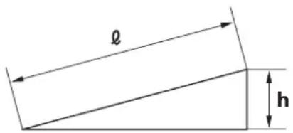
| Lengthof Ramp( l) | 2.5m (8.2ft) | 3.0m (9.8ft) | 3.5m (11.5ft) |
| Height(h) | 50cm (1.6ft) | 60cm (2.0ft) | 70cm (2.3ft) |
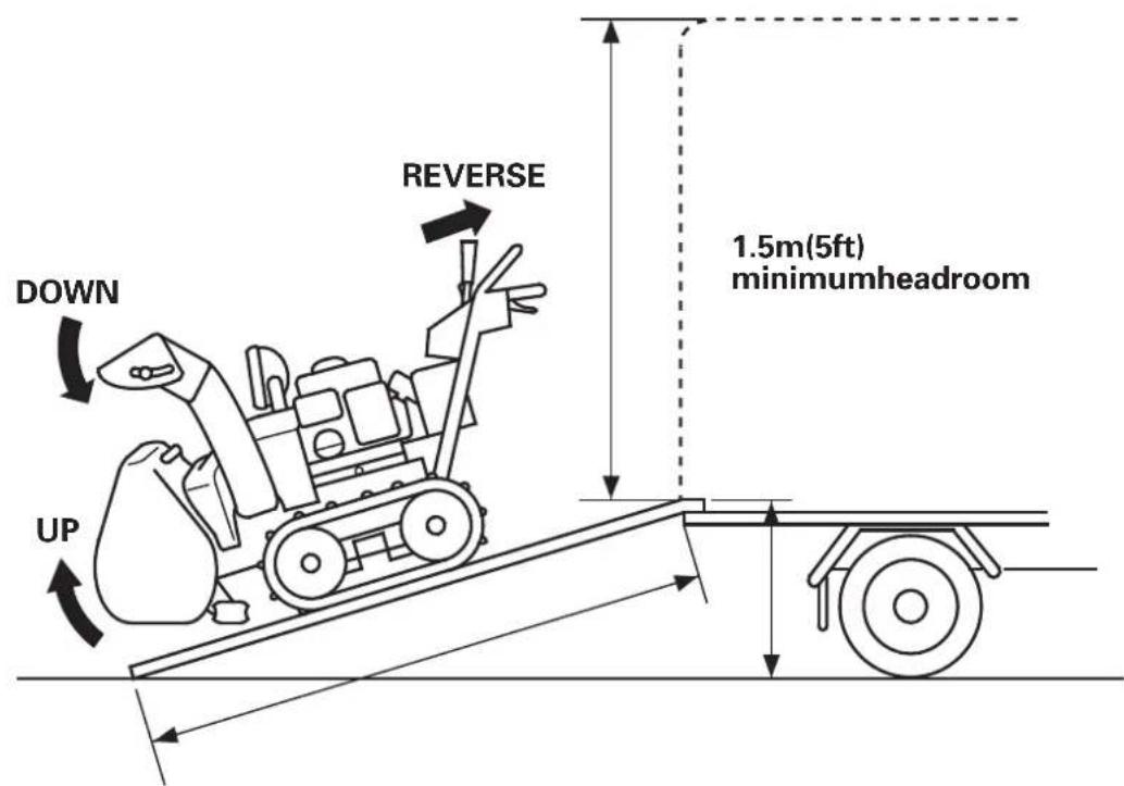
- Ifthesnowbloweristobetransportedonatruckhavingahood, checkthatthedistancebetweenthetruckbedandhoodis1.5m(5 ft)ormore.Removethedischargechuteifthedistanceislessthan 1.5m(5ft).
- Beforeloading, check that there is sufficient fuel in the tank. Engine may stall on therampif there is little fuel in the tank.
Loading
- Squeezetheheightadjustlever, and raisetheaugertotheHIGH position(P.).22
- Lowerthedischargechuteallthewaydownbyoperatingthe dischargechuteadjustswitch.
- Usereversegeartobackthesnowbloweruptheramp.
- Useextremecarenottohitthedischargechuteagainstthehood on anyotherpartsoftthetruck.
WARNING
- Avoidstoppingthesnowblowerontheramp.Shouldtheengine stop, besuretomovetheshiftleverbacktotheNEUTRALbefore attemptingtostarttheengine.
- NeverleavethetransmissionreleaseeverintheRELEASED positionwhileloading;thesnowblowermaystartsuddenly, resultinginseriousinjuryoraccident.
Tiethesnowblowerdownwithropeorstraps, and blockthetreads. Keepethe-downropeorstrapsawayfromcontrolsandcables.
Donottiewithropeorstrapsstrongerthannecessarytoprevent snowblowerpartsfrombreaking.
Tie-downpoints
Front
Rear
Tracktype:

Wheeltype:
withbatterywithoutbattery
Beforestoringthesnowblowerforanextendedperiod:
- Besurethestorageareaisfreeofexcessivehumidityanddust.
2.Drainthefuel.
WARNING
- Gasoline is extremely flammable and explosive under certain conditions. Donotsmokeorallowflamesorsparksinthearea.
- Donotdrainthefueltankwhentheexhaustsystemishot.
a. TurnthefuelvalveON.
b. Loosenthecarburetordrainknob, anddrainthegasolineintoa suitablecontainer. Afterdraining, retightenedrainknoband turnthefuelvalveOFF.
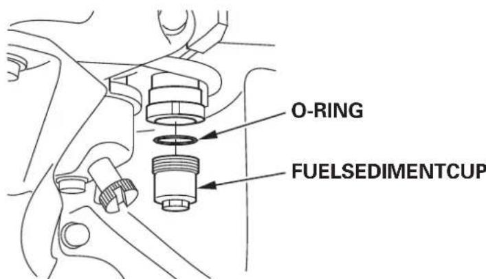
- Cleanthefuelsedimentcup.
a. TurnthefuelvalveOFF,removeemptyandcleanthefuel sedimentcup.
b. ReinstallthecupandO-ringandtightensecurely.
- Removethesparkplugandpourthreetablespoonsfulofclean motoroiltothecylinder.Pullthestarterropeslowlytwoorthreetimestodistributetheol. Reinstallthesparkplug.
- Pullthestartergripuntilresistanceisfelt.Thisclosesthevalvesand protectstheenginefrominternalcorrosion.
(ETS,EWS)
- Batteryservice Ifthesnowblowerwillbestoredforanextendedperiod,removethe batteryandstoreinacool, dryplacewiththenegativeterminal disconnectedfromthebattery.Rechargeitevery6months.
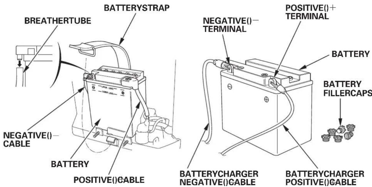
Batteryremoval/charging/installation
Batterychargerwhichiscommerciallyavailablefor12Vbatteriescan beusedtochargethebattery:
(1) Removethebatterycoverandcheckthebatteryelectrolytelevel (seepage)32
(2) Removethenegative()cablefromthebatterynegative() terminal;thenremovethepositive()cablefromthebattery positive()terminal.
(3) Removethebattery strapfromthebottom hook.
Disconnect the breathertube and remove the battery.
(4) Remove the battery fillercaps, and connect the battery charger positive() cabletothebatterypositive()terminal; then connect the battery chargernegative() cabletothebattery negative()terminal.
(5) Charge the battery: 510 hours at 1.2A (HSS970).
510hoursat1.8A (HSS1380).
(6) Install thebatteryinthereverseorderofremoval.
Thisssymbolonthebatterymeansthatthisproductmustnot betreatedashousehold waste.
NOTE:
Animproperlydisposedofbatterycanbeharmfultotheenvironment andhumanhealth.
Alwaysconfirmlocalregulationsforbatterydisposal.
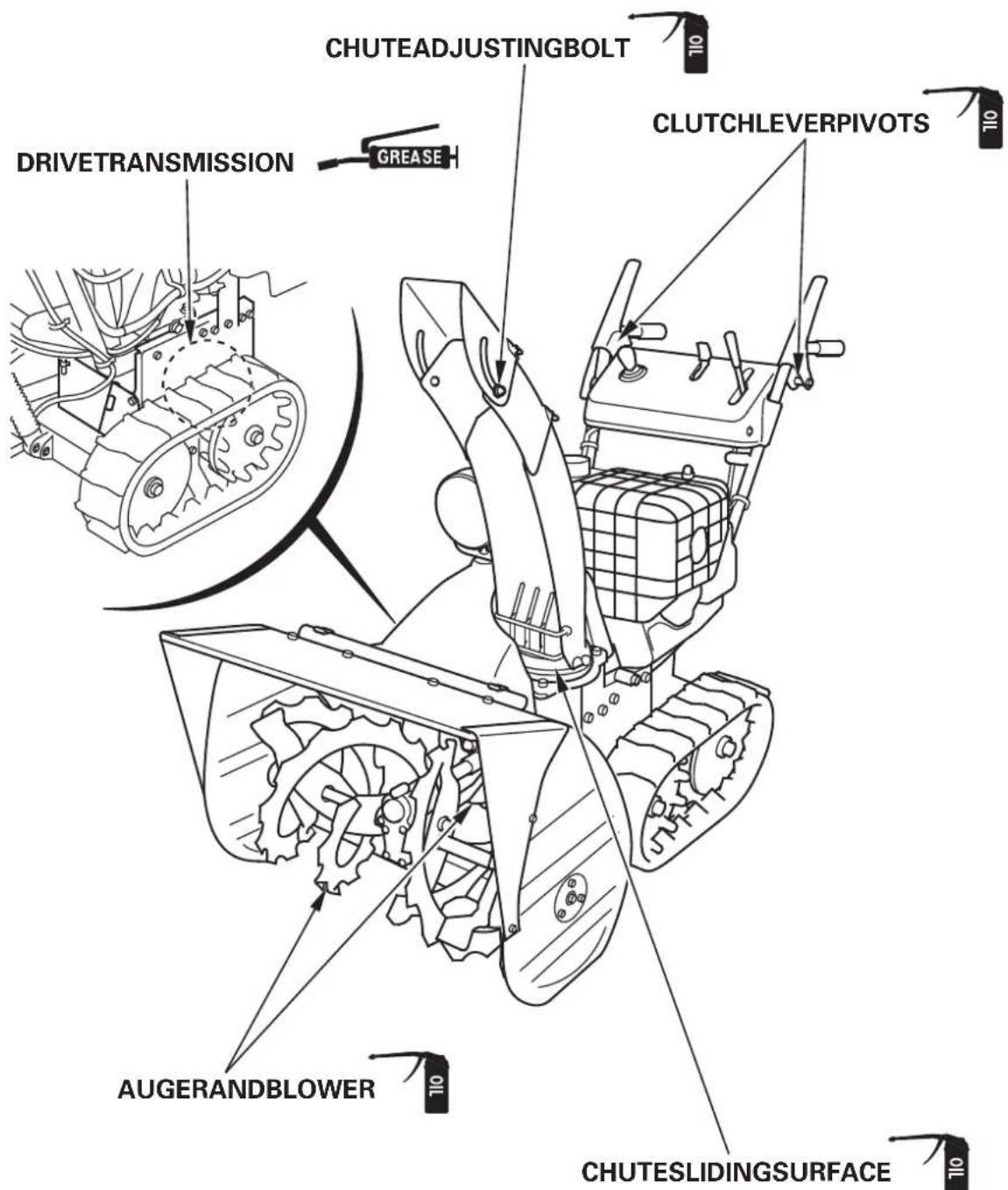
Applyoiltothefollowingpartsforlubricationandrustprevention.7.
Whentheenginewillnotstart:
- Isthereenoughfuel?
- Isthefuelvalveon?
- Isgasolinereachingthecarburetor? Tocheck,loosenedthedrainknobwiththefuelvalveon.Fuelshould flowfreely.
WARNING
Gasolineisextremelyflammable,andgasolinevaporcanexplode. Ifanyfuelisspilled,makesuretheareaisdrybeforetestingthespark plugorstartingtheengine.Spilledfuelorfuelvapormayignite.
- Istheengineswitchon?
- Checkthesparkplugfordirt, wetandthegap.
a. Cleanthesparkplug.
b. Reinstalltheplugifitisreused,orreplacewithanewone. - If the engine still does not start, take these now blowertoan authorized Hondadealer.
Iftheaugerorblowerdoesnotoperate,checkthelockbolts(page). 34 Replacementlockboltsandnutsweresuppliedwithyoursnowblower. AdditionalallockboltsandnutsareavailablefromauthorizedHonda snowblowerdealers.Donotreplacelockboltswithordinaryhardware bolts.
Iftheenginestopswhilesnowdischarging:
- Isthereenoughfuel? (ETS,EWS)
-
Doestheauger-lockindicatorblink?
-
Thesnowblowerstopsthengineandblinkstheauger-lock indicatorwhenaforeignobjectisincriminatedintherotatingauger orothersimilarproblemisgoneon. Turnofftheindicatorinaccordancewiththecorrectinstructions.
- Thebatterycapacitymaybelowedwhenthetroubleisnotfound intheaugerandengineisstopped. Inthiscase, charge the battery or replace it.
| Model | HSS970 |
| Descriptioncode | SAPJ |
Engine
| Model | GX270 |
| EngineNetpower(in accordance with SAE J1349*) | 6.3kW(8.6PS)/3,600rpm |
| Displacement | 270cm³ (16.5cu-in) |
| Borestroke | 77.058.0mm(3.02.3in)× × |
| Startingmethod | Recoilsterer,Recoilerelectricstarter |
| Ignitionsystem | CDImagneto |
| Oilcapacity | 1.10L(1.16USqt,0.97lmpqt) |
| Fueltankcapacity | 5.0L(1.32USgal,1.10lmpgal) |
| Sparkplug | , W16EPR-U(DENSO)BPR5ES |
| Battery | 1 2 V 1 2 A / 1 0 H R |
Frame
| Type Items | TracktypeWheel type | |||
| EWEW$ ET | ETS | |||
| Overalllength | 1,465mm(57.7in)1,500mm(59.1in) | |||
| Overallwidth | 725mm(28.5in) | |||
| Overallheight | 1,115 mm (43.9 in) | 1,170 mm (46.1 in) | 1,125 mm (44.3 in) | 1,170 mm (46.1 in) |
| Drymass[weight] | 100kg(220lbs)110kg(243lbs)115kg(254lbs)120kg(265lbs) | |||
| Widthofsnowclearance | 710mm(28.0in) | |||
| Heightofsnowclearance | 510mm(20.1in) | |||
| Snowthrowingdistance (differsaccordertothe kindofsnow) | Max.16m(52.8ft) | |||
| Clearingcapacity | 50Ton/hour | |||
- The power rating of the engine indicated in this document is the net power output tested on a production engine for the engine model and measured in accordance with SAE J1349 at 3,600 rpm (Engine Net Power). Mass production engines may vary from this value.
Actual power output for the engine installed in the final machine will vary depending on numerous factors, including the operating speed of the engine in application, environmental conditions, maintenance, and othervariables.
NOTE:
Specifications are subject to change without notice.
| Model | HSS1380 |
| Descriptioncode | SASJ |
Engine
| Model | GX390 |
| EngineNetpower (inaccordancewithSAEJ1349) * | 8.7kW(11.8PS)/3,600rpm |
| Displacement | 389cm³ (23.7cu-in) |
| Borestroke | 88.064.0mm(3.52.5in)× × |
| Startingmethod | Recoilsterer,Recoilerelectricstarter |
| Ignitionsystem | CDImagneto |
| Oilcapacity | 1.10L(1.16USqt,0.97lmpqt) |
| Fueltankcapacity | 5.7L(1.51USgal,1.25lmpgal) |
| Sparkplug | BPR5ES(NGK)W16EPR-U(DENSO) |
| Battery | 1 2 V 1 8 A / 1 0 H R |
Frame
| Type Items | Tracktype | |
| ETETS | ||
| Overalllength | 1,500mm(59.1in) | |
| Overallwidth | 825mm(32.5in) | |
| Overallheight | 1,125mm(44.3in)1,170mm(46.1in) | |
| Drymass[weight] | 125kg(276lbs)135kg(298lbs) | |
| Widthof snowclearance | 810mm(31.9in) | |
| Heightof snowclearance | 510mm(20.1in) | |
| Snowthrowingdistance (differsaccordertothe kindof snow) | Max.17m(56.1ft) | |
| Clearingcapacity | 65Ton/hour | |
- Thepowerratingoftheengineindicatedinthisdocumentisthenet power output tested on a production engine for the engine model and measured in accordance with SAE J1349 at 3,600 rpm (Engine Net Power). Mass production engines may vary from this value. Actual power output for the engine installed in the final machine will vary depending on numerous factors, including the operating speed of the engine in application, environmental conditions, maintenance, and othervariables.
NOTE:
Specifications are subject to change without notice.
NoiseandVibration
| Model | HSS970HSS1380 | |
| Soundpressurelevelat operator'sears (ENISO11200:1995) | 86dB(A) | 87dB(A) |
| Uncertainty | 2 dB (A) | 2 dB (A) |
| Measuredsoundpowerlevel (2000/14/EC,2005/88/EC) | 100dB(A) | 102dB(A) |
| Uncertainty | 2 dB (A) | 1 dB (A) |
| Guaranteedsoundpowerlevel (2000/14/EC,2005/88/EC) | 102dB(A) | 103dB(A) |
| Vibrationlevelathandarm (EN12096:1997AnnexD, EN1033:1995) | 7.5m/s2 | 5.7m/s2 |
| Uncertainty | 2.1m/s2 | 1.4m/s2 |
MEMO
MEMO
MANUELDEL'UTILISATEUR
Noticeoriginale
- AmenerleleviderdesgazsurlapositionSLOW.

- AmenerleboutondecontactmoteursurlapositionOFF(arryt).
(ETS,EWS)
Manovelladellaboccadidiscarica(ET,EW)
Usarequestamanovellaperpuntarelaboccadiscaricaversodestraoversosinistra.
For further information, please contact Honda Customer Information Centre at the following address: telephonenumber:
ADRESSESDESPRINCIPAUXDISTRIBUTEURSHonda
BALTICSTATES (Estonia/Latvia/Lithuania)
HondaMotorEuropeLtd.
EstonianBranch
Tulika15/17
10613Tallinn
Tel.:3726801300
Fax:3726801301
honda.baltichonda-eu.com.
BELGIUM
HondaBelgium
Doornveld180-184
1731Zellik
Tel.:3226201000
Fax:3226201001
http://www.honda.be
BH_PERONDA-EU.COM
CROATIA
Hongoldoniad.o.o.
JelkoveckaCesta5
10360SesveteZagreb
Tel.:38512002053
Fax:38512020754
http://www.hongoldonia.hr
jurehongoldonia.hr
CYPRUS
AlexanderDimitriou&SonsLtd.
162,YiannosKranidiotisAvenue
2235Latsia,Nicosia
Tel.:35722715300
Fax:35722715400
CZECHREPUBLIC
BGTechnikcs,a.s.
UZavodiste251/8
15900Prague5-Velka
Chuchle
Tel.:420283870850
Fax:420266711145
http://www.honda-stroje.cz
BULGARIADENMARKGREECE
KirovLtd.TimaProductsA/SGeneralAutomotiveCoS.A.
49TsaritsaYoanablvd
1324Sofia
Tel. +35929330892
Fax:35929330814
http://www.kirov.net
hondakirov.net
Tarnfalkvej16
2650Hvidovre
Tel. +4536342550
Fax:+4536771630
http://www.tima.dk
FINLAND
OYBrandtAB.
Tuupakantie7B
01740Vantaa
Tel.:358207757200
Fax:35898785276
http://www.brandt.fi
FRANCE
HondaRelationsClients
TSA80627
45146StJeandelaRuelleCedex
Tel.:0238813390
Fax:0238813391
http://www.honda-fr.com
espaceclientnda-eu.com
GERMANY
NETHERLANDSREPUBLICOF
HondaNederlandB.V.
Afd,PowerEquipment
Capronilaan1
1119NNSchiphol-Rijk
Tel.:31207070000
Fax:31207070001
http://www.honda.nl
P.O.Box454
1401Ski
Tel. +4764860500
Fax:+4764860549
http://www.berema.no
Beremaberema.no
IRELANDPOLAND
TwoWheelsLtdAriesPowerEquipmentSp.zo.o.
M50BusinessPark,Ballymount
Dublin12
Tel.:35314381900
Fax:35314607851
http://www.hondaireland.ie
Servicekondaireland.ie
ul.Wroclawska25
01-493Warszawa
Tel.:48(22)8614301
Fax:48(22)8614302
http://www.ariespower.pl
21.MKAD47km.,Leninskydistrict.
Moscowregion,142784Russia
Tel.:7(495)7452080
Fax:7(495)7452081
http://www.honda.co.ru
品 postofficehonda.co.ru
SERBIA&
MONTENEGRO
BazisGrupad.o.o.
GrcicaMilenka39
11000Belgrade
Tel.:381113820295
Fax:381113820296
http://www.hondasrbija.co.rs
SLOVAKIAREPUBLIC
HondaSlovakia,spol.sr.o.
Prievozká682109Bratislava
Tel.:421232131112
Fax:421232131111
http://www.honda.sk
SLOVENIA
ASDomzaleMotoCenterD.O.O.
Blatnica3A
1236Trzin
Tel.:38615622242
Fax:38615623705
http://www.as-domzale-motoc.si
SPAIN&
LasPalmasprovince
(Canary Islands)
GreensPowerProducts,S.L.
PolygonIndustrialCongost
AvRamonCiuransn°2
08530LaGarriga-Barcelona
Tel.:34938605025
Fax:34938718180
http://www.hondaencasa.com
Tenerifeprovince
(Canary Islands)
AutomocionCanariasS.A.
CarreteraGeneraldelSur,KM.8,8
38107SantaCruzdeTenerife
Tel.:34(922)620617
Fax:34(922)618042
http://www.aucasa.com

ventas@ucasa.com

taller@casa.com
SWEDEN
HondaNordicAB
Honda(UK)PowerEquipment
470LondonRoad
Slough-Berkshire,SL38QY
EC Declaration of Conformity
-
The undersigned, Piet Renneboog, on behalf of the authorized representative, herewith declares that the machinery described below fulfils all the relevant provisions of:
-
Directive 2006/42/EC on machinery
- Directive 2004/108/EC on electromagnetic compatibility
-
Directive 2000/14/EC - 2005/88/EC on outdoor noise
-
Description of the machinery
a) Generic denomination: Snow thrower
b) Function: removing snow
c) Commercial name d) Type e) Serial number
1 1
- Manufacturer
Honda Motor Co., Ltd.
2-1-1 Minamiaoyama
Minato-ku, Tokyo, JAPAN
- Authorized representative
Honda Motor Europe Ltd. Aalst Office
- References to harmonized standards 6. Other
standards or specifications
- Outdoor noise Directive
a) Measured sound power dB(A): 1
b) Guaranteed sound power dB(A): 1
c) Noise parameter (kW/min ^-1 ): *1
d) Conformity assessment procedure: ANNEX V
e) Notified body:
- Done at:
- Date:
Piet Renneboog
Homologation Manager
Honda Motor Europe, Ltd., Aalst Office