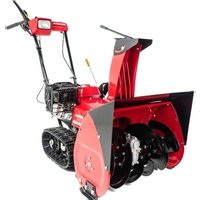
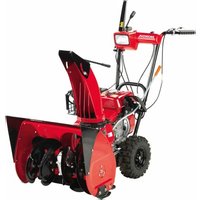
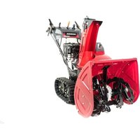
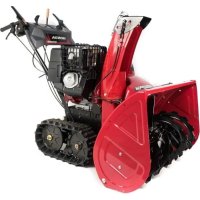
HSS 655 TD - Snow blower Honda - Free user manual and instructions
Find the device manual for free HSS 655 TD Honda in PDF.


| Product type | Snow blower |
| Brand | Honda |
| Model | HSS 655 TD |
| Engine | GX160, 163 cm³, 3.6 kW (4.9 hp) at 3600 rpm |
| Starting | Manual recoil starter or electric starter (depending on version) |
| Fuel | Unleaded gasoline, 3.1 L tank |
| Engine oil | SAE 5W-30, capacity 0.58 L |
| Clearing width | 550 mm |
| Clearing height | 420 mm (model HSS622) / 500 mm (HSS655) |
| Discharge distance | Up to 14 m |
| Cleaning capacity | 35 to 37 tons per hour depending on model |
| Dimensions (L x W x H) | 1500 x 550 x 1110 mm (track type) |
| Dry weight | 65 to 75 kg depending on version |
| Transmission | Tracks or wheels depending on version |
| Speeds | 2 forward + 1 reverse |
| Headlight | Yes (depending on version) |
| Spark plug | BPR5ES (NGK) or W16EPR-U (DENSO), gap 0.7-0.8 mm |
| Battery (if applicable) | 12 V, 10 Ah/10 HR |
| Sound level | Sound pressure 85 dB(A) / guaranteed power 100 dB(A) |
| Hand-arm vibration | 9.5 m/s² |
| Maintenance | Annual oil change, spark plug cleaning, track/tire adjustment |
| Safety | Engine stop, clearing tools, warning stickers |
Frequently Asked Questions - HSS 655 TD Honda
User questions about HSS 655 TD Honda
0 question about this device. Answer the ones you know or ask your own.
Ask a new question about this device
Download the instructions for your Snow blower in PDF format for free! Find your manual HSS 655 TD - Honda and take your electronic device back in hand. On this page are published all the documents necessary for the use of your device. HSS 655 TD by Honda.
USER MANUAL HSS 655 TD Honda
natural_image
Line drawing of a mechanical device with no visible text or symbolsOWNER'S MANUAL MANUEL DE L'UTILISATEUR BEDIENUNGSANLEITUNG MANUALE DELL'UTENTE
OWNER'S MANUAL
Original instructions
MANUEL DE L'UTILISATEUR
Notice originale
BEDIENUNGSANLEITUNG
ECOLOGY CONSCIOUS TECHNOLOGY
The “e-SPEC” mark symbolizes environmentally responsible technologies applied to Honda power equipment, which contains our wish to “preserve nature for generations to come.”
Thank you for purchasing a Honda snowblower.
This manual covers the operation and maintenance of Honda snowblower: HSS622/HSS655
All information in this publication is based on the latest product information available at the time of approval for printing.
Honda Motor Co., Ltd. reserves the right to make changes at any time without notice and without incurring any obligation.
No part of this publication may be reproduced without written permission.
This manual should be considered a permanent part of the snowblower and should remain with the snowblower if it is resold.
Pay special attention to statements preceded by the following words:
⚠ WARNING Indicates a strong possibility of severe personal injury or death if instructions are not followed.
CAUTION: Indicates a possibility of personal injury or equipment damage if instructions are not followed.
NOTE: Gives helpful information.
If a problem should arise, or if you have any questions about your snowblower, consult an authorized Honda dealer.
▲WARNING
Operating this equipment requires special effort to ensure the safety of the operator and the safety of others. Read and understand this Owner's Manual before operating this equipment; failure to do so could result in personal injury or equipment damage.
The illustrations herein are mainly based on: ETS.
- The illustration may vary according to the type.
Disposal
To protect the environment, do not dispose of this product, battery, engine oil, etc. carelessly by leaving them in the waste.
Observe the local laws and regulations or consult your authorized Honda dealer for disposal.
1.SAFETY INSTRUCTIONS ....3
2.SAFETY LABEL LOCATIONS....9
CE mark and noise label locations.... 12
3.COMPONENT IDENTIFICATION 13
4.CONTROLS 16
5.PRE-OPERATION CHECK 24
6.STARTING THE ENGINE 29
Carburetor Modification for High Altitude Operation.... 35
7.SNOWBLOWER OPERATION.... 36
8.STOPPING THE ENGINE 44
9.MAINTENANCE 45
10.STORAGE....58
11.TROUBLESHOOTING.... 61
12.SPECIFICATIONS.... 62
MAJOR Honda DISTRIBUTOR ADDRESSES ...... Inside back cover
“EC Declaration of Conformity” CONTENT OUTLINE .... Inside back cover
WARNING
To ensure safe operation—
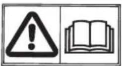
- Honda snowblower is designed to give safe and dependable service if operated according to instructions. Read and understand this Owner's Manual before operating the snowblower. Failure to do so could result in personal injury or equipment damage.
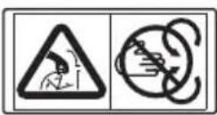
- Never put your hand into the snow discharge chute while the engine is running; serious personal injury could result.
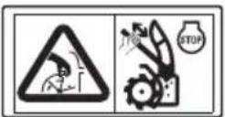
- If the snow discharge chute becomes clogged, stop the engine and use a snow drop bar or a wooden stick to unclog it. - Never put your hand into the snow discharge chute while the engine is running; serious personal injury could result.
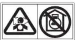
- Exhaust contains poisonous carbon monoxide, a colorless, odorless gas. Breathing carbon monoxide can cause loss of consciousness and may lead to death. - If you run the snowblower in an area that is confined, or even partially enclosed area, the air you breathe could contain a dangerous amount of exhaust gas. - Never run your snowblower inside a garage, house, or near open windows or doors.
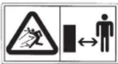
- Keep all persons and pets away from the snowblower area.
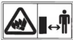
- Never stand or work around or near the auger while the engine is running. Your feet may be caught on the auger when the auger is accidentally started, increasing the risk of serious personal injury.
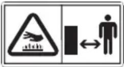
- A hot exhaust system can cause serious burns. Avoid contact if the engine has been running.
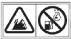
- Gasoline is extremely flammable and is explosive under certain conditions.
- Do not smoke or allow flames or sparks in the area where the snowblower is refueled or where gasoline is stored.
- Refuel in a well-ventilated area with the engine stopped.
- Do not overfill the fuel tank, and make sure the fuel tank cap is closed securely after refueling.
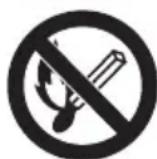
- Keep flames and sparks away from the batteries. Batteries produce explosive gas that can cause explosion.
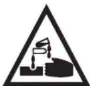
- Handle the battery electrolyte with extreme care as it contains dilute sulfuric acid. Contact with your skin or eyes can burn you or cause loss of your eyesight.

- Do not allow children and other people to touch a battery unless they understand proper handling and hazards of the battery very well.

- Do not use a battery with the electrolyte at or below the lower level mark. It can explode causing serious injury.

- Wear the eye protection and rubber gloves when handling the batteries, or you can get burned or lose your eyesight by the battery electrolyte.

- Read this manual carefully and understand it before handling the batteries. Neglect of the instructions can cause personal injury and damage to the snowblower.
Operator responsibilities
- Know how to stop the snowblower quickly, and understand the operation of all controls.
- Never permit anyone to operate the snowblower without proper instruction. If people or pets suddenly appear in front of the snowblower while it is in operation, immediately release the auger and drive clutch levers to stop the snowblower and avoid possible injury from rotating auger blades.
▲WARNING
To ensure safe operation—
• Always make a pre-operation check (pages 24 through 28) before you start the engine. You may prevent an accident or equipment damage.
- Honda snowblowers are designed to give safe and dependable service if operated according to instructions. Read and understand this Owner's Manual before operating the snowblower. Failure to do so could result in personal injury or equipment damage.
- Before operating the snowblower, inspect the area in which you are going to clear snow. Remove debris and other obstacles the snowblower might strike or throw, as they may cause injury or damage to the snowblower.
- Inspect the snowblower before operating it. Repair any damage and correct any malfunction before operation.
If you hit an obstacle while operating the snowblower, stop the engine immediately, and check for damage. Damaged equipment may increase the possibility of injury during operation.
- Do not use the snowblower when visibility is poor. Under conditions of poor visibility, there is a greater risk of striking an obstacle or causing injury.
- Never use the snowblower to clear snow from a gravel road or driveway, as rocks may be picked up and ejected. They may cause injury to bystanders.

natural_image
Illustration of a person cleaning a small robot on the ground, no text or symbols present▲WARNING
- Adjust the snow discharge chute to avoid hitting the operator, bystanders, windows, and other objects with ejected snow. Stay clear of the snow chuter while the engine is running.
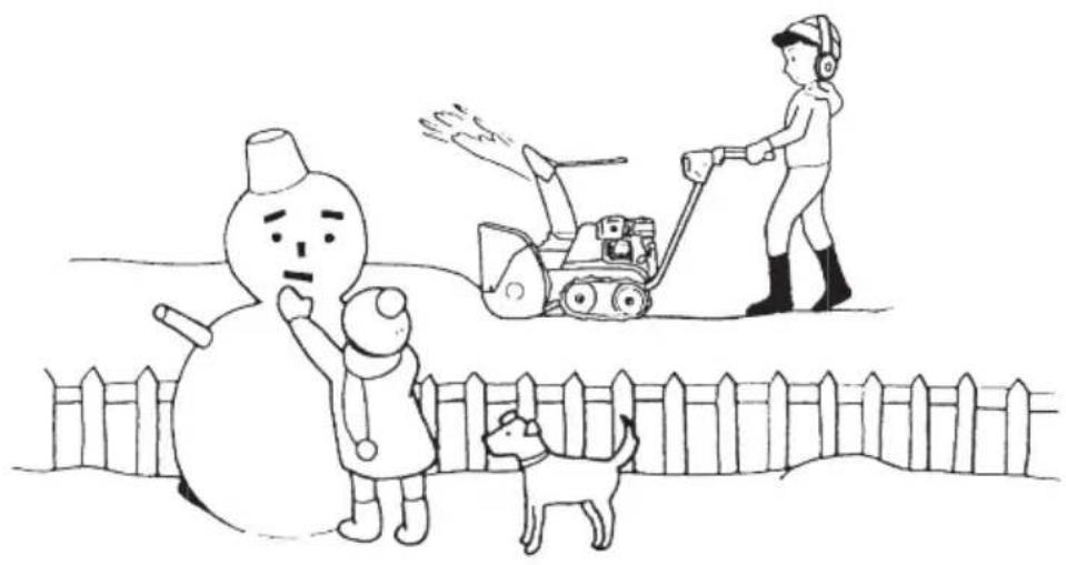
- Children and pets must be kept away from the area of operation to avoid injury from flying debris and contact with the snowblower.
- Do not use the snowblower to remove snow from roofs.
- To avoid overturning, be careful when changing the direction of the snowblower while operating it on a slope.
- The snowblower may overturn on steep slopes if left unattended, causing injury to the operator or bystanders.
- Do not use the snowblower on a slope of more than 10^ (17%).
- The maximum safe grade angle shown is for reference purposes only. To avoid tipping the snowblower over, stay off slopes too steep for safe operation. The risk of snowblower upset is even higher when the surface is loose, wet or uneven.
- Before starting the engine, check that the snowblower is not damaged and in good condition. For your safety and safety of others, exercise extreme care when using the snowblower up or down hill.
- If the snow discharge chute becomes clogged, stop the engine and use the snow clearing bar or a wooden stick to unclog it.
Never put your hand into the snow discharge chute while the engine is running; serious personal injury could result.
natural_image
Cartoon illustration of a snowman, a child, and a dog near a fence with a bulldozer (no text or symbols)▲WARNING
- Never run the engine in an enclosed or confined area. Exhaust contains poisonous carbon monoxide gas; exposure can cause loss of consciousness and may lead to death.
- The muffler becomes very hot during operation and remains hot for a while after stopping the engine. Be careful not to touch the muffler while it is hot. Let the engine cool before storing the snowblower indoors.
- Stop the engine and let it cool before operating covers for inspection and other servicing.
- Carefully check the area before backing the snowblower up or while working in reverse.
- For your safety and the safety of others, do not operate the snowblower during darkness if it is not equipped with a headlight.
NOTE:
While operating the snowblower, hold the handle firmly and walk, don't run. Wear suitable winter boots that resist slipping.
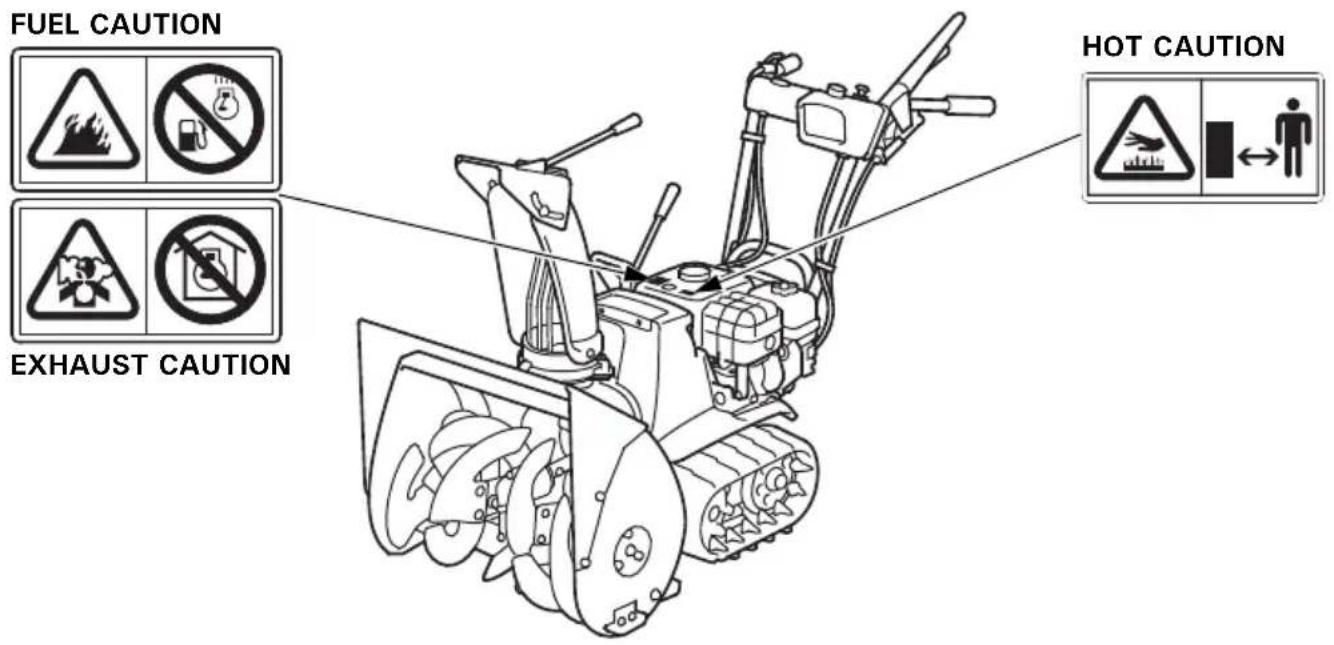
These labels warn you of potential hazards that can cause serious injury. Read the labels and safety notes and precautions described in this manual carefully.
If a label comes off or becomes hard to read, contact your Honda dealer for a replacement.
[ETS, HT, HTS, ET, EW and LW types]
READ OWNER'S MANUAL
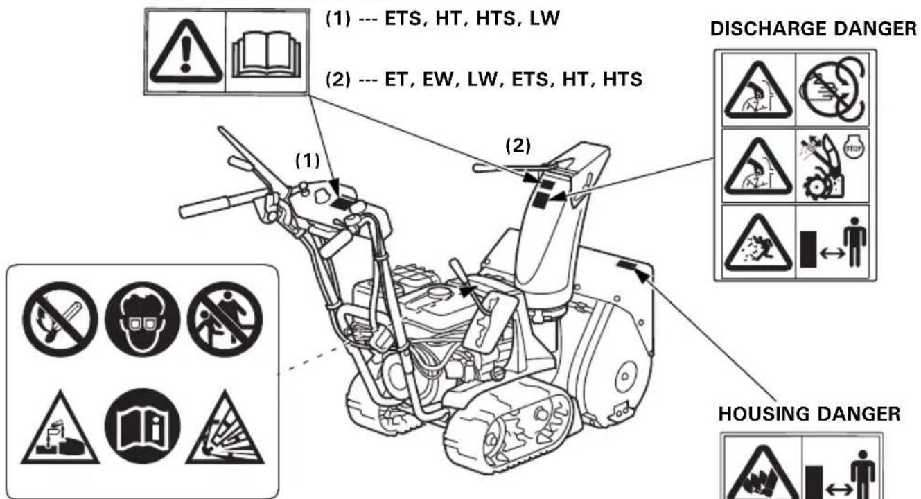
BATTERY CAUTION
(ETS and HTS types only)
[TC and TCS types]
![Honda HSS 655 TD - [TC and TCS types] - 1](/content/2026/04/668923/images/a6e655a9760c04e757c42b38601d6444d63d6af9227b045b5163cb7b77c47af9.jpg)
*: French labels come with the snowblower.
CE mark and noise label locations
[ETS, HT, HTS, ET, EW and LW types]
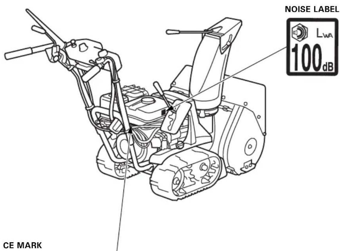
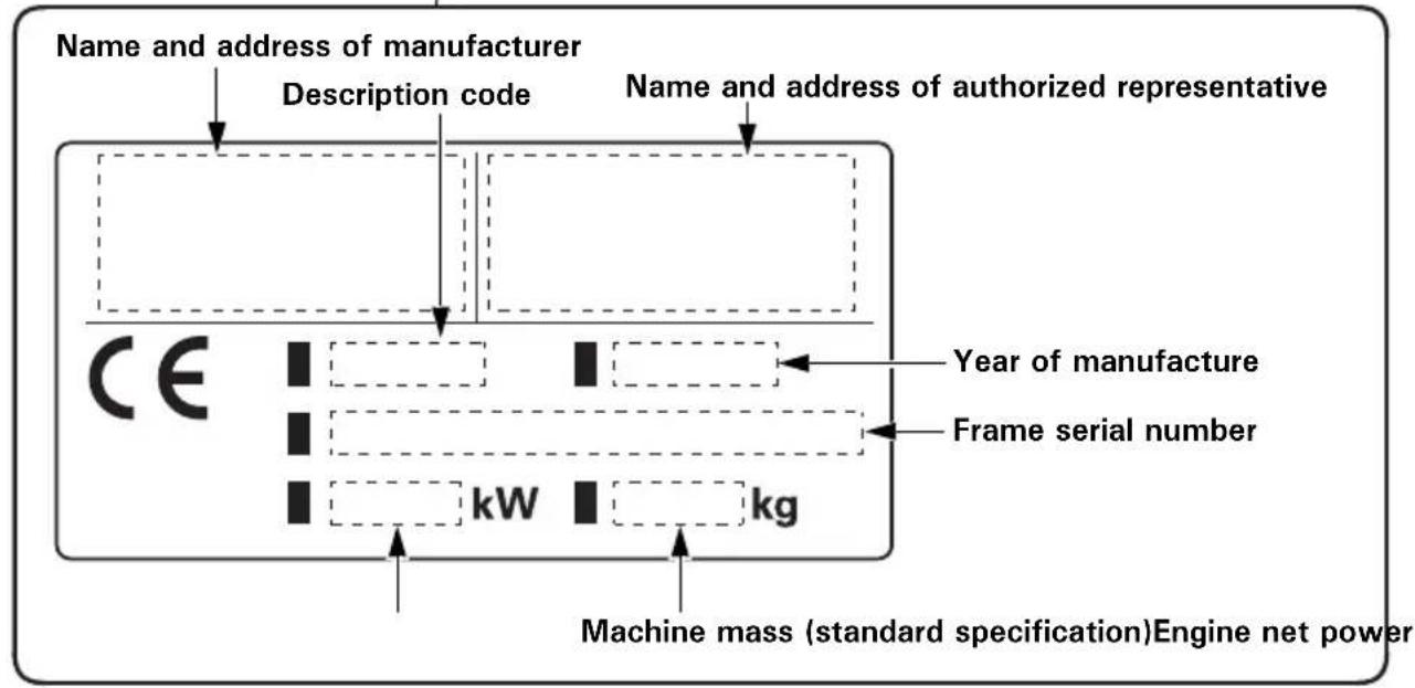
Name and address of manufacturer and authorized representative are written in the "EC Declaration of Conformity" CONTENT OUTLINE in this Owner's Manual.
TRACK TYPE (ET, HT, ETS, HTS, TC and TCS types)
WHEEL TYPE (EW and LW types)

natural_image
Line drawing of a snowman lawn tool with visible blades and wheels (no text or symbols)FRAME SERIAL NUMBER*
*The frame serial number on the products for Europe (ET, ETS, HT, HTS, EW and LW types) is described on the CE mark label (see page 12).
Record the frame serial number in the space below. You will need this serial number when ordering parts.
Frame serial number:
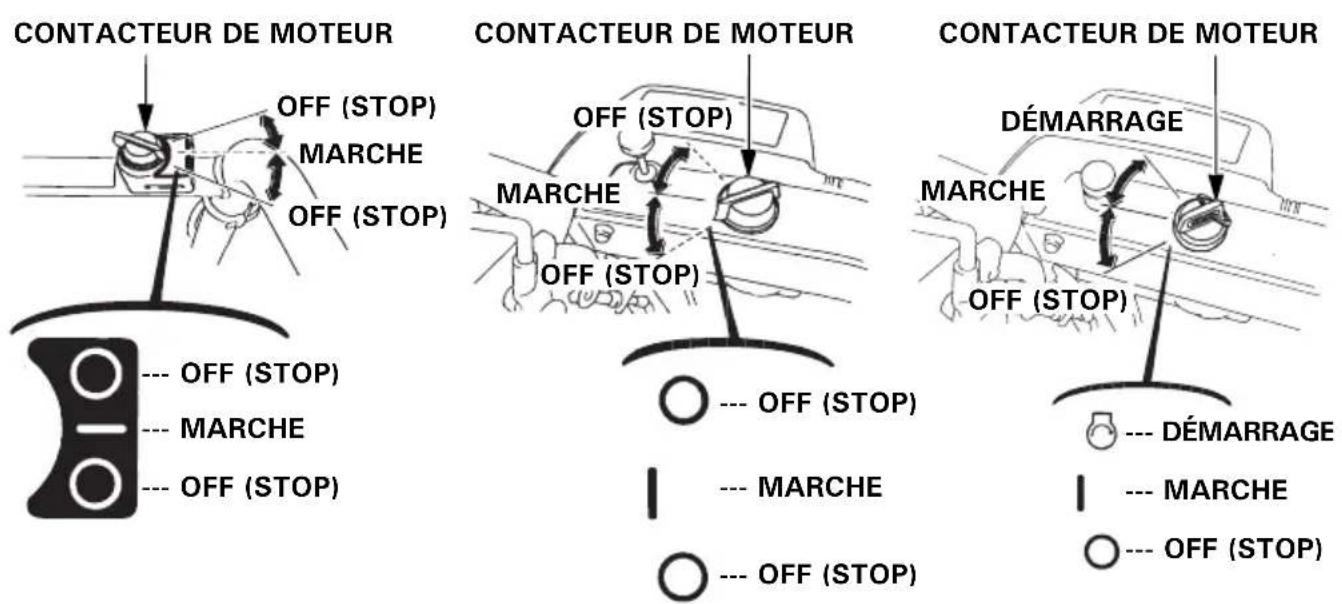
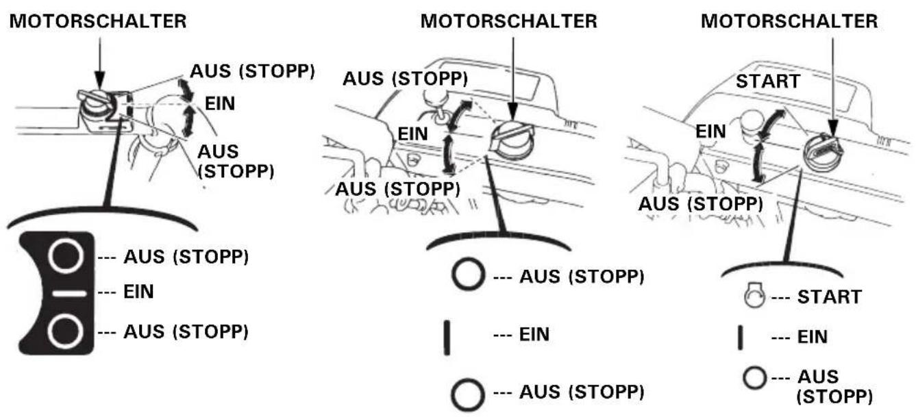
Engine switch
Use the engine switch to turn the ignition system on for starting, and to stop the engine.
(ET, EW, TC)
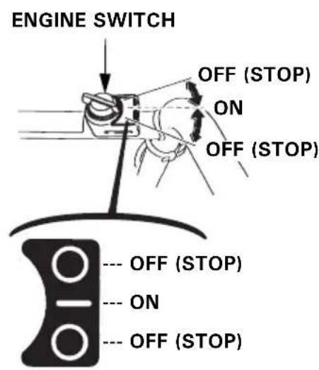
(HT, LW, TCS)
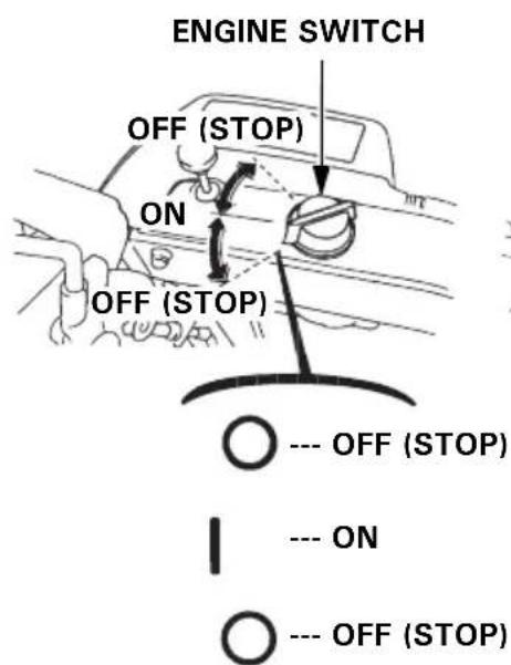
(ETS, HTS)
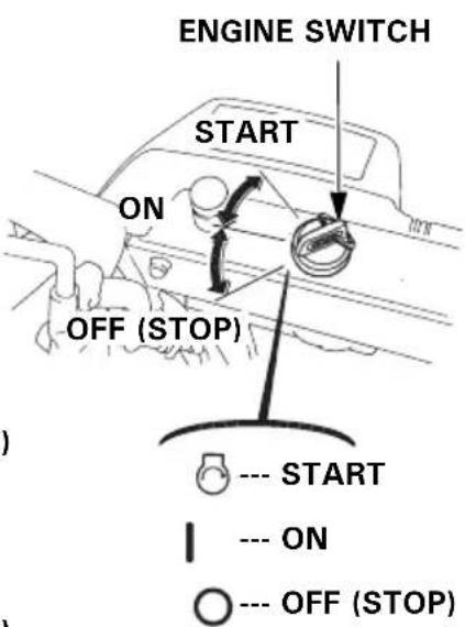
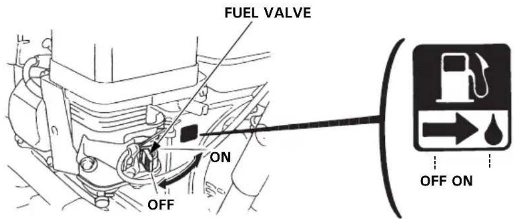
Fuel valve
The fuel valve opens and closes the fuel line leading from the fuel tank to the carburetor. Make sure that the valve is positioned exactly at either the ON or OFF position.
▲WARNING
Before transporting the snowblower, be sure to turn the fuel valve to OFF to prevent possible fuel leaks; spilled fuel or fuel vapor may ignite.
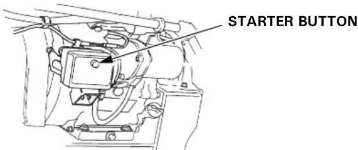
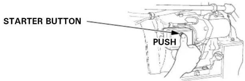
AC starter button (TCS)
Push the starter button to operate the electric starter.
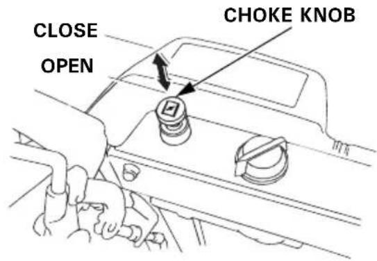
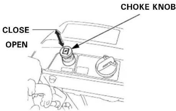
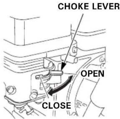
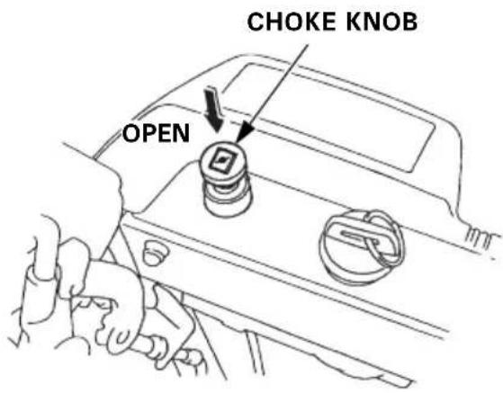
Choke knob
Close the choke when the engine is cold or difficult to start.
(ET, EW) (HT, LW)

(ETS, HTS)
(TC, TCS)
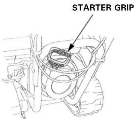
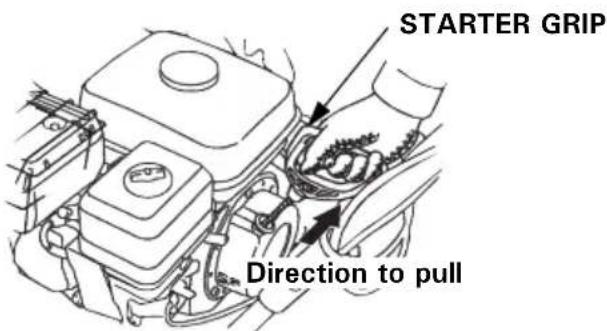
Starter grip
Pulling the starter grip operates the recoil starter to crank the engine for starting.
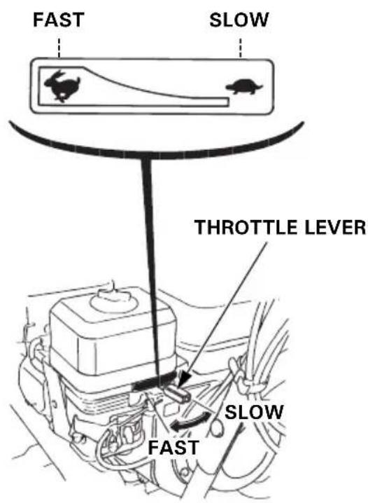
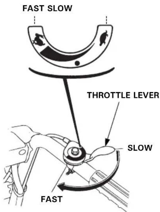
Throttle lever (engine speed)
Use the throttle lever to select engine speed. In normal operation, use the “FAST” position.
(HT, HTS, TC, TCS)
(ET, ETS, EW, LW)
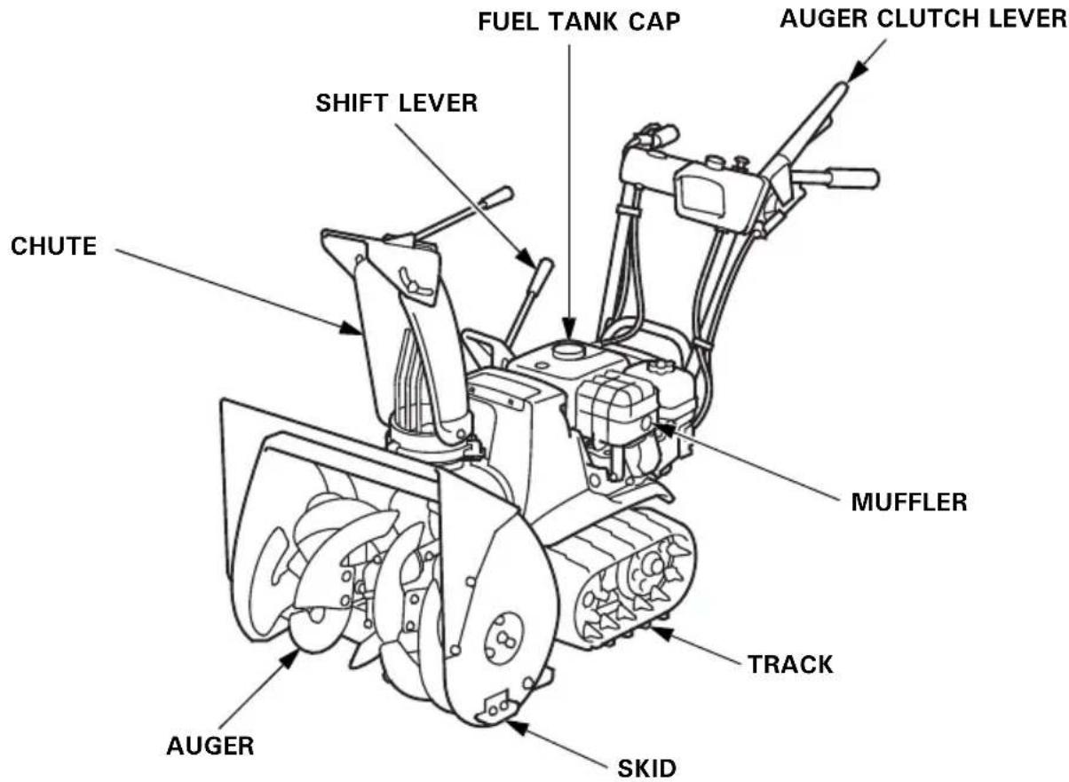
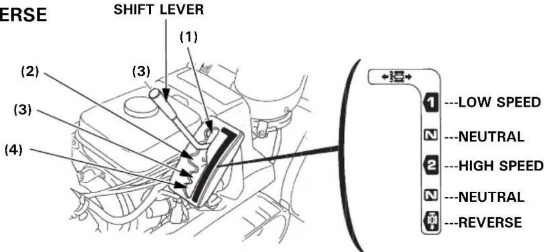
Shift lever
Use the shift lever to select drive speed or direction.
(1): LOW SPEED
(2): HIGH SPEED
(3): NEUTRAL
(4): REVERSE
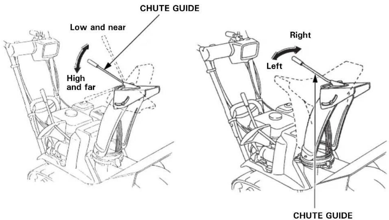
Chute guide
The chute guide controls the snow discharge angle and direction.
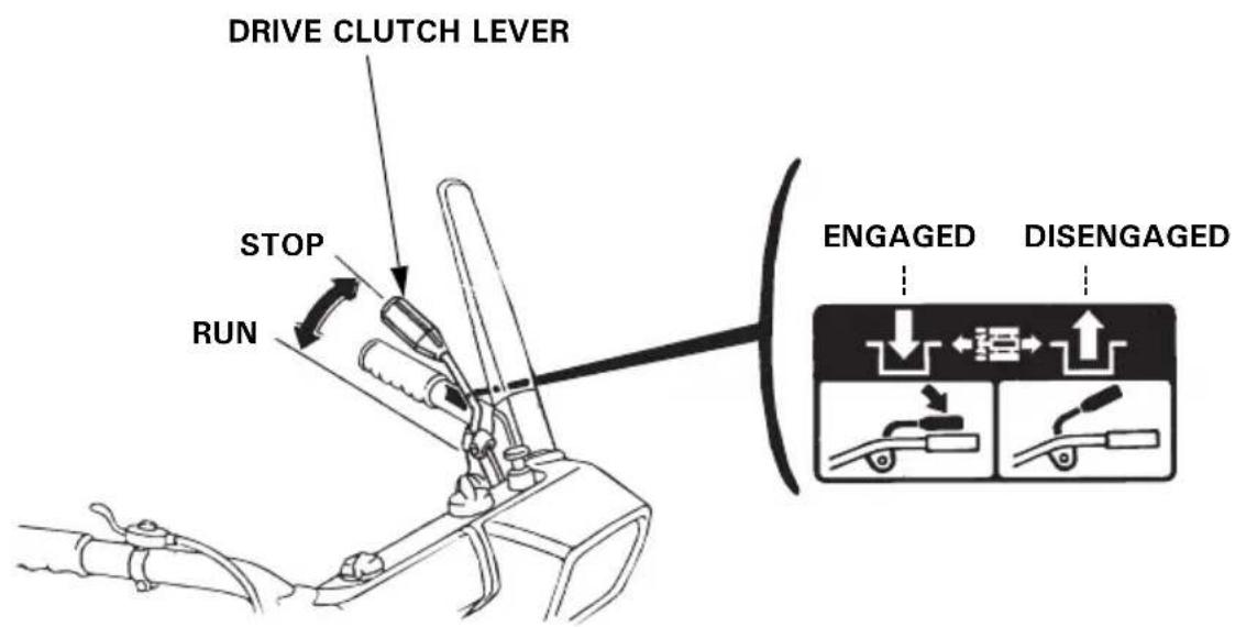
Drive clutch lever
Use the drive clutch lever to propel or stop the snowblower.
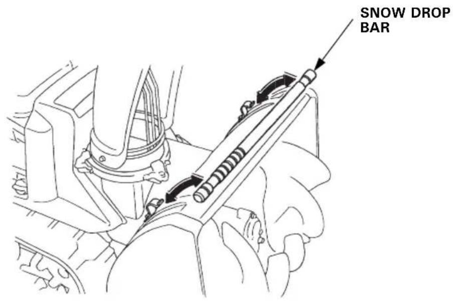
Snow drop bar
If the snow discharge chute or snow blowing mechanism becomes clogged, stop the engine and use this bar to unclog them. After unclogging, wipe the bar clean, and store it in the holders.
WARNING
Before removing clogged snow, be sure to stop the engine, and make sure that all rotating parts have come to a complete stop. Remove the spark plug cap from the spark plug.
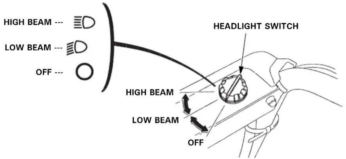
Headlight switch (ETS, HTS, HT, LW, TCS)
The switch turns the headlight, low beam, high beam and OFF. To turn the headlight on, it is necessary to start the engine first. It will remain off while the engine is off.
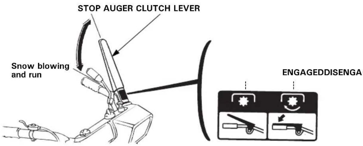
Auger clutch lever
Squeezing the auger clutch lever also operates the drive clutch lever; the snow blowing mechanism starts and the snowblower moves forward. Releasing the auger clutch lever stops both the snow blowing mechanism and the forward motion of the snowblower.
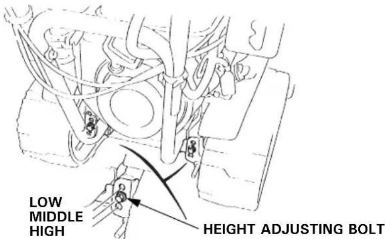
Height adjusting bolt (track type only)
Use the bolt for adjusting the height and angle of the machine in relation to the tracks.
Raise or lower the machine to the desired position. (See page 36)
LOW : Hard snow or fine finish
MIDDLE : Normal use
HIGH : Deep snow or for transporting the snowblower.
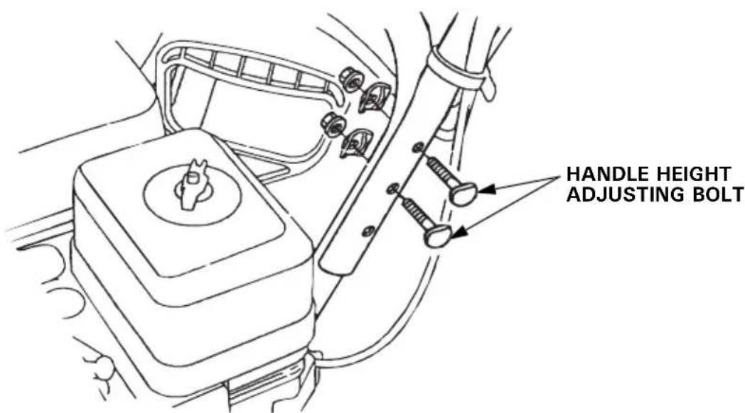
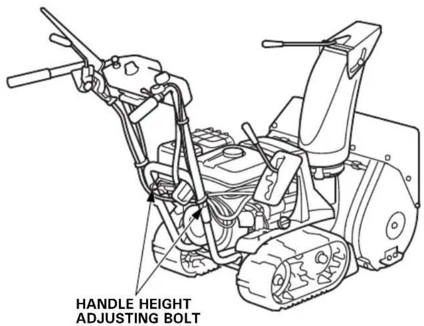
Handle height adjusting bolt
The handlebars can be set in the high, low or middle position to suit the operator. To change handlebar height, remove the right and left adjusting bolts, align the bolt holes for the desired handlebar height, and reinstall the bolts. Tighten the nuts securely.
Skid plate, scraper
Adjust the skid plates and scraper for the auger housing ground clearance best suited to your snow removal conditions. (See page 36)
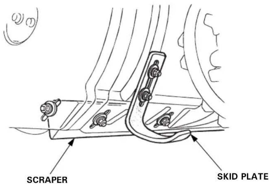
Skid
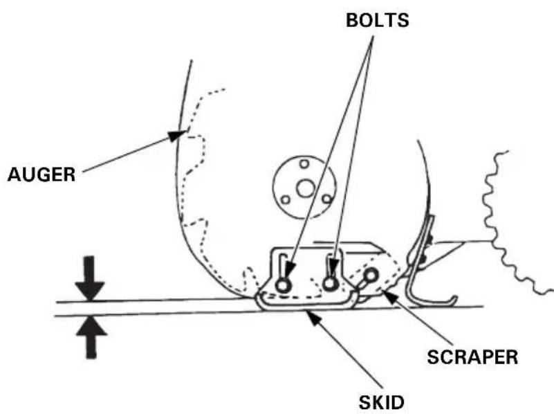
Adjust the skid and the scraper according to the road surface condition where you are to clear the snow. Use the skid to determine the height from the ground to the auger, and adjust the scraper to make the snow surface even (see page 37).
Check the snowblower on level ground with the engine stopped.
▲WARNING
To prevent accidental start-up, remove the engine switch key, and disconnect the spark plug cap before performing the pre-operation check.
Do not overfill the fuel tank (there should be no fuel in the filler neck). After refueling, make sure the fuel tank cap is closed properly and securely.
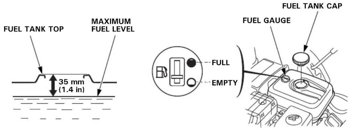
Fuel level
Inspection:
Check whether the fuel gauge needle is in the FULL position. If the needle is not in the position, fill the fuel tank to the level shown.
Refilling:
Remove the fuel tank cap and fill the tank with the recommended gasoline.
Do not fill the fuel tank completely. Fill tank to approximately 35 mm (1.4 in) below the top of the fuel tank to allow for fuel expansion.
After refueling, make sure the fuel tank cap is closed properly and securely.
Use unleaded gasoline with a Research Octane Number of 91 or higher (a Pump Octane Number of 86 or higher).
Never use stale or contaminated gasoline or an oil/gasoline mixture.
Avoid getting dirt or water in the fuel tank.
▲WARNING
- Gasoline is extremely flammable and is explosive under certain conditions.
- Refuel in a well-ventilated area with the engine stopped.
Do not smoke or allow flames or sparks in the area where the engine is refueled or where gasoline is stored. - Do not overfill the fuel tank (there should be no fuel in the filler neck).
After refueling, make sure the fuel tank cap is closed properly and securely. - Be careful not to spill fuel when refueling. Spilled fuel or fuel vapor may ignite. If any fuel is spilled, make sure the area is dry before starting the engine.
- Avoid repeated or prolonged contact with skin or breathing of vapor. KEEP OUT OF REACH OF CHILDREN.
CAUTION:
Don't let snow get in the fuel tank. Water in the fuel system can cause stalling and difficult starting.
NOTE:
Gasoline spoils very quickly depending on factors such as light exposure, temperature and time.
In worst cases, gasoline can be contaminated within 30 days.
Using contaminated gasoline can seriously damage the engine (clogged carburetor, stuck valve).
Such damage due to spoiled fuel is disallowed from coverage by the warranty.
To avoid this please strictly follow these recommendations:
- Only use specified gasoline (see page 24).
- Use fresh and clean gasoline.
- To slow deterioration, keep gasoline in a certified fuel container.
- If long storage (more than 30 days) is foreseen, drain fuel tank and carburetor (see page 58).
GASOLINES CONTAINING ALCOHOL
If you decide to use a gasoline containing alcohol (gasohol), be sure its octane rating is at least as high as that recommended by Honda.
There are two types of “gasohol”: one containing ethanol, and the other containing methanol.
Do not use gasohol that contains more than 10% ethanol.
Do not use gasoline containing more than 5% methanol (methyl or wood alcohol) and that does not also contain co-solvents and corrosion inhibitors for methanol.
NOTE:
- Fuel system damage or engine performance problems resulting from the use of gasoline that contains more alcohol than recommended is not covered under the warranty.
- Before buying gasoline from an unfamiliar station, first determine if the gasoline contains alcohol, if it does, find out the type and percentage of alcohol used.
If you notice any undesirable operating symptoms while using a particular gasoline. Switch to a gasoline that you know contains less than the recommended amount of alcohol.
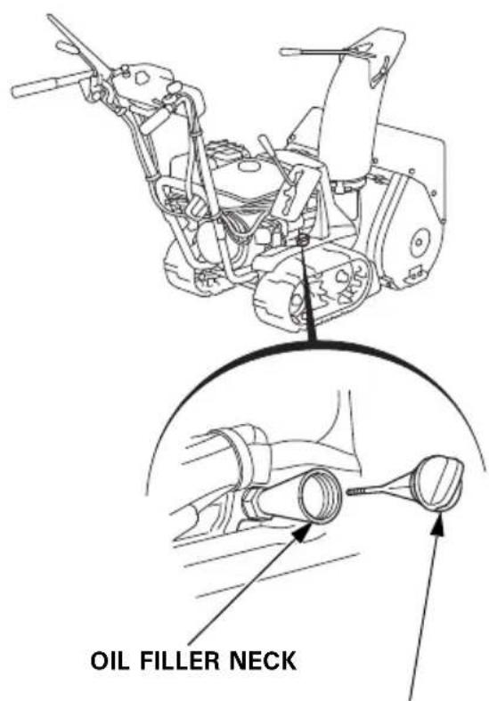
Engine oil level
Inspection:
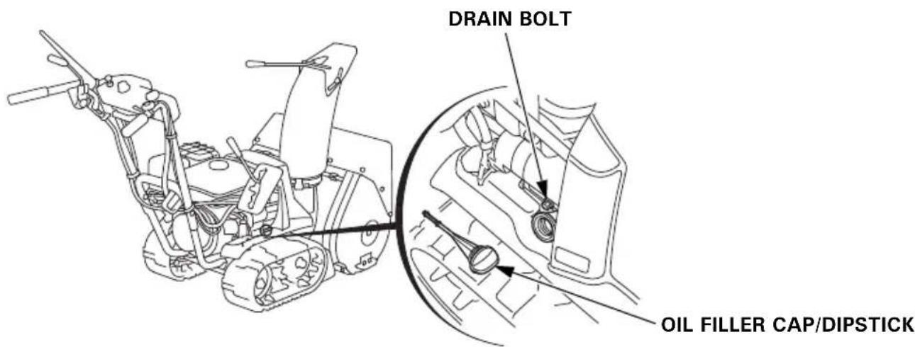
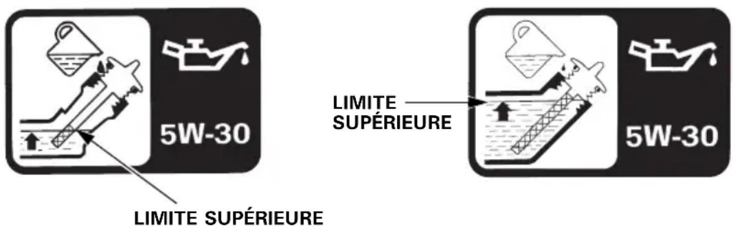
With the snowblower on a level surface, remove the oil filler cap/dipstick.
(ETS and HTS types)
Wipe the dipstick clean. Insert the dipstick into the filler neck, but do not screw it in.
Remove the dipstick.
Check the oil level.
If the oil level is lower than the upper limit, fill to the upper limit with the recommended oil on following page. Do not overfill.
Change the oil if it is excessively contaminated or discolored. (Refer to page 48 for the engine oil change interval and procedure.)
(ETS, HTS)
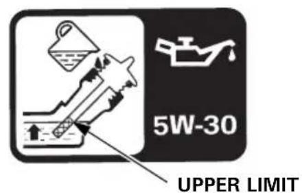
(ET, HT, EW, LW, TC, TCS)
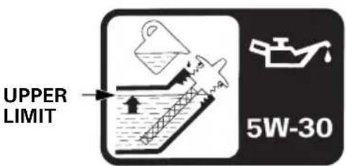
OIL FILLER CAP/DIPSTICK
QUANTITY SPECIFIED: 0.58 L (0.61 US qt, 0.51 Imp qt)
RECOMMENDED OIL:
Use 4-stroke motor oil that meets or exceeds the requirements for API service classification SE or later (or equivalent).
Always check the API service label on the oil container to be sure it includes the letters SE or later (or equivalent).
SAE 5W-30 is recommended for general use.
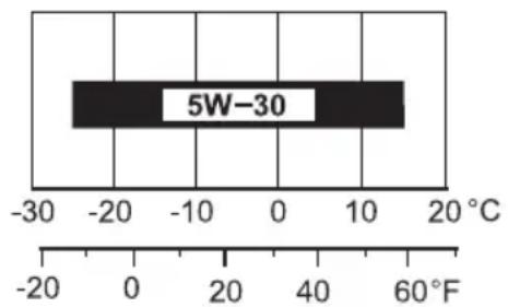
AMBIENT TEMPERATURE
CAUTION:
- Engine oil is a major factor affecting engine performance and service life. Nondetergent oils and 2-stroke engine oils are not recommended because of inadequate lubricating properties.
- Running the engine with insufficient oil can cause serious engine damage.
▲WARNING
Never run the engine in an enclosed or confined area. Exhaust contains poisonous carbon monoxide gas; exposure can cause loss of consciousness and may lead to death.
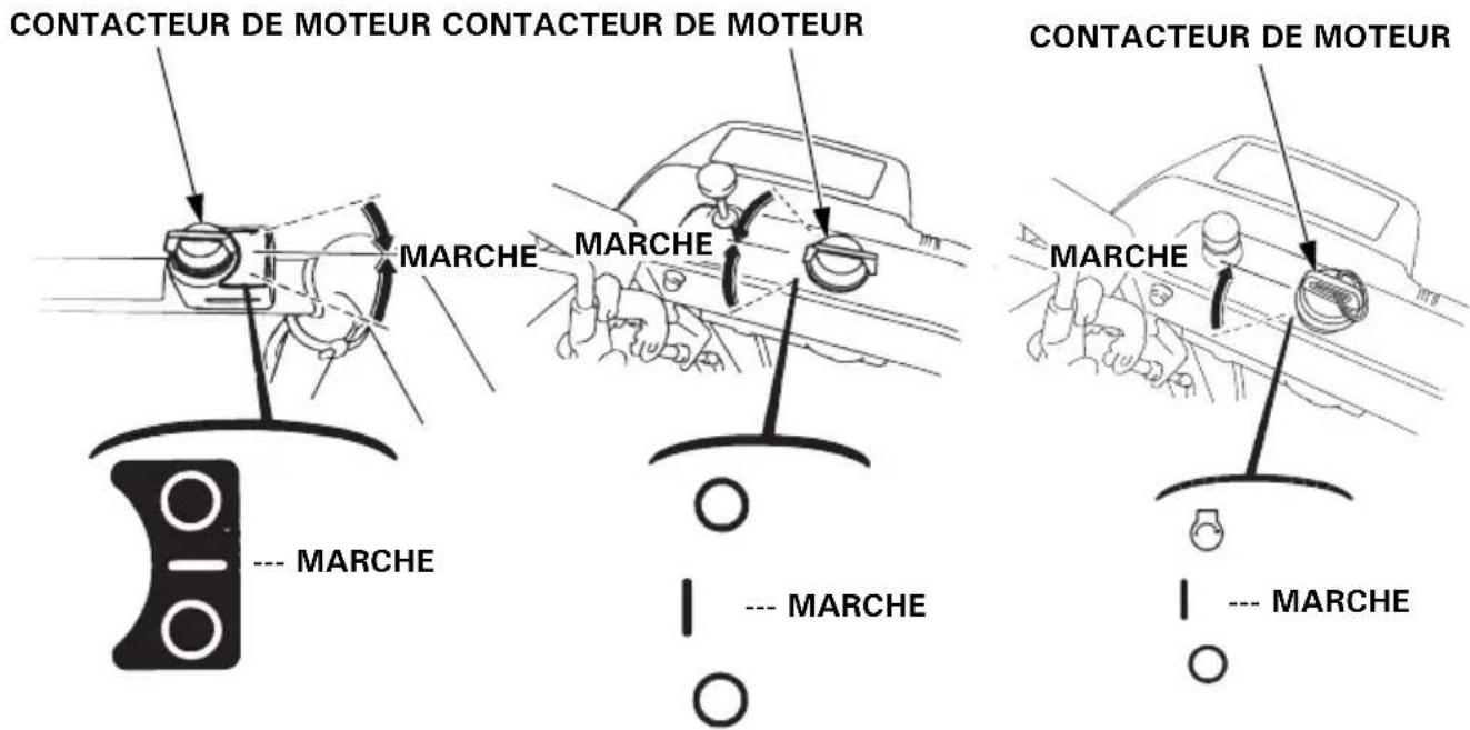
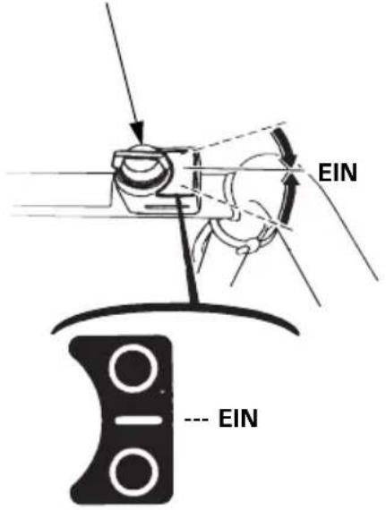
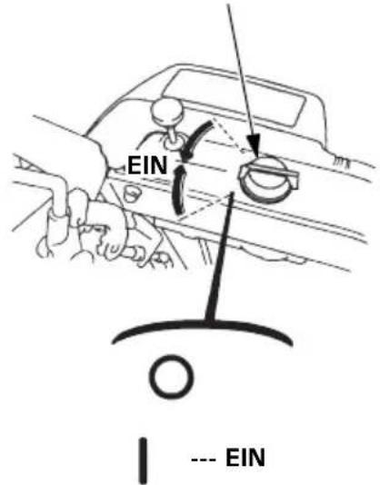
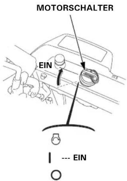
- Turn the engine switch to the ON position.
(ET, EW, TC)
(HT, LW, TCS)
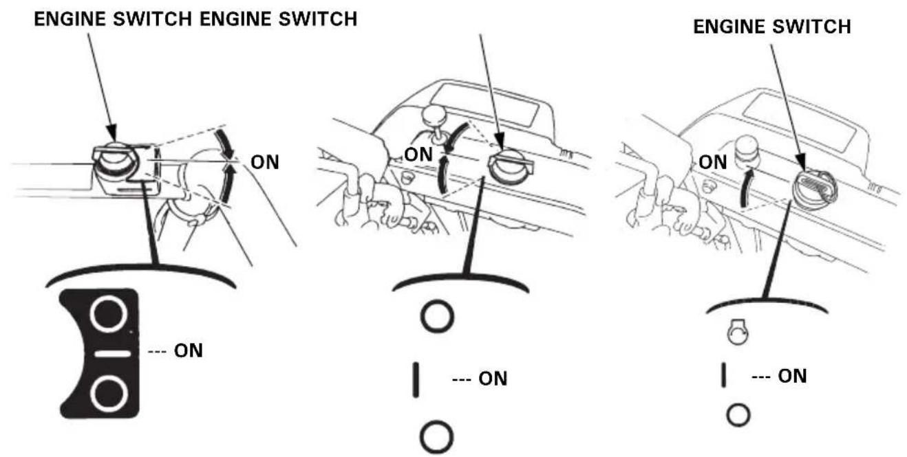
(ETS, HTS)
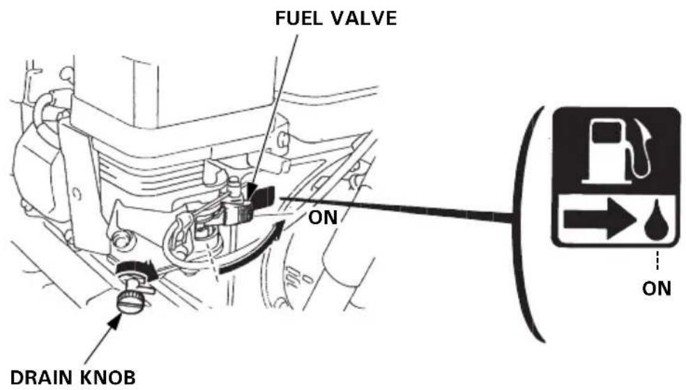
- Turn the fuel valve to the ON position.
Be sure that the drain knob is tightened securely.
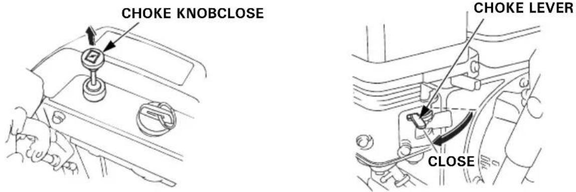
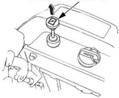
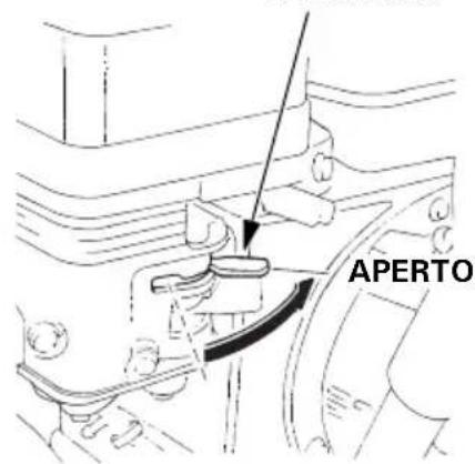
- In cold weather and when the engine is cold, move the choke knob to the CLOSE position.
(ET, EW) (HT, LW)
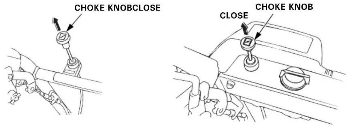
(ETS, HTS) (TC, TCS)
[AC Electric starting] (TCS)
- Connect the female end of your power cord to the switch box and the male end to a properly grounded 120 Volt A/C outlet.
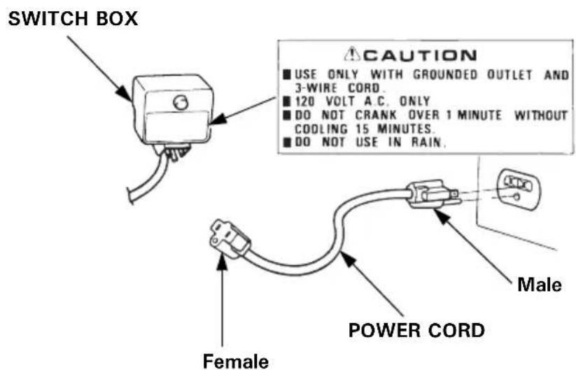
▲WARNING
- To minimize the possibility of potentially dangerous electrical shocks, always use a 3-conductor power cord with a power rating of no less than 15 amps. Also, be sure that the outlet you are using is properly grounded.
- Do not connect and disconnect the power cord with wet hands.
- Be sure to hold the plug when disconnecting the power cord from the electrical outlet or switch box. Do not disconnect by pulling on the power cord.
5.Push the starter button until the engine starts.
CAUTION:
- Do not operate the starter for more than 1 minute. If the engine fails to start, release the button and allow the starter to cool for 15 minutes before operating it again.
- To avoid serious engine damage, never operate the starter while the engine is running.
• After the engine starts, disconnect the power cord from the electrical outlet first, and then from the switch box.
[MANUAL STARTING ONLY]
- Pull the starter grip lightly until you feel resistance, then pull briskly in the direction of the arrow as shown below.
CAUTION:
- Do not allow the starter grip to snap back against the engine. Return it gently to prevent damage to the starter.
- Damage may result if the starter grip is pulled while the engine is running.
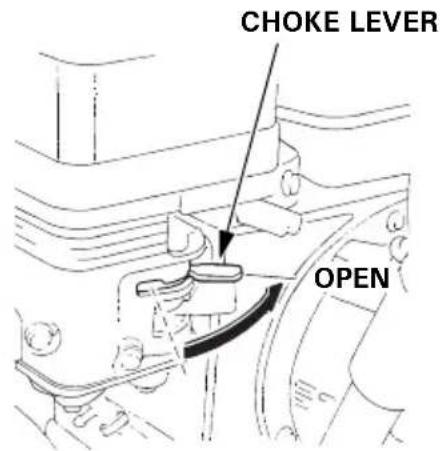
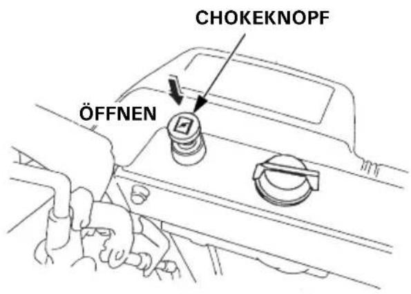
- Let the engine warm up for several minutes. If the choke knob has been pulled to the CLOSE position, push it gradually to the OPEN position as the engine warms up.
(ET, EW) (HT, LWCHOKE KNOB
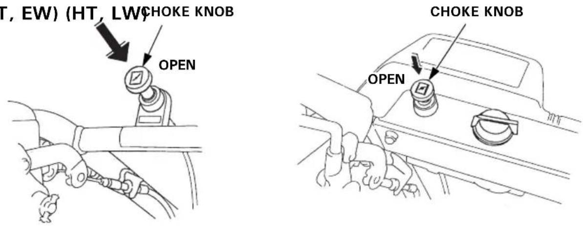
(ETS, HTS) (TC, TCS)
[DC Electric starting] (ETS, HTS)
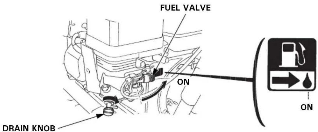
- Turn the fuel valve to the ON position.
Be sure that the drain knob is tightened securely.
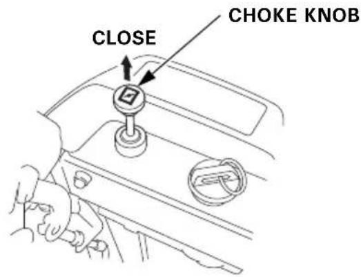
- In cold weather and when the engine is cold, pull the choke knob to the CLOSE position.
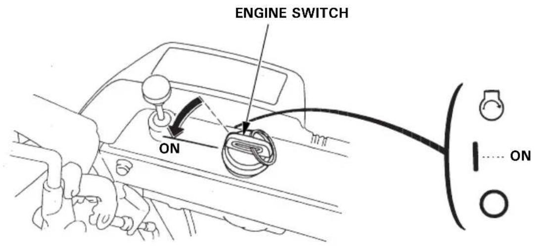
3.Turn the engine switch to the ON position.
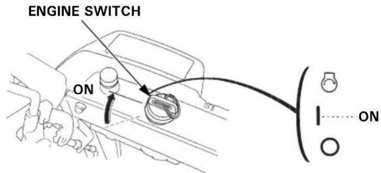
- Turn the engine switch to START and hold it there until the engine starts.
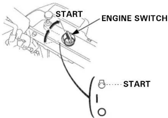
CAUTION:
Do not use the starter motor for more than 5 seconds. If the engine fails to start, release the key, and wait at least 10 seconds before operating the starter motor again.
NOTE:
When the speed of the starter motor drops after a period of time, it is an indication that the battery should be recharged.
- When the engine starts, release the key, allowing the switch to return to the ON position.
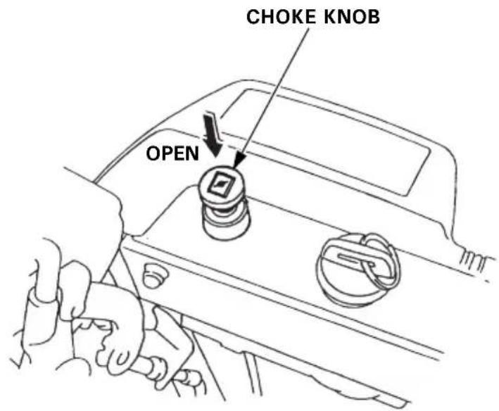
- Let the engine warm up for several minutes. If the choke knob has been pulled to the CLOSE position, push it gradually to the OPEN position as the engine warms up.
Carburetor Modification for High Altitude Operation
At high altitude, the standard carburetor air-fuel mixture will be too rich. Performance will decrease, and fuel consumption will increase. A very rich mixture will also foul the spark plug and cause hard starting. Operation at an altitude that differs from that at which this engine was certified, for extended periods of time, may increase emission.
High altitude performance can be improved by specific modifications to the carburetor. If you always operate your snowblower at altitudes above 1,500 meters (5,000 feet), have your authorized Honda servicing dealer perform this carburetor modification.
This engine, when operated at high altitude with the carburetor modifications for high altitude use, will meet each emission standard throughout its useful life.
Even with carburetor modification, engine horsepower will decrease about 3.5% for each 300 meter (1,000 foot) increase in altitude. The effect of altitude on horsepower will be greater than this if no carburetor modification is made.
CAUTION:
When the carburetor has been modified for high altitude operation, the air-fuel mixture will be too lean for low altitude use. Operation at altitudes below 1,500 meters (5,000 feet) with a modified carburetor may cause the engine to overheat and result in serious engine damage. For use at low altitudes, have your servicing dealer return the carburetor to original factory specifications.
Skid plate, scraper
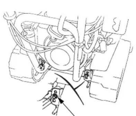
Adjust the skid plate and scraper positions.
▲WARNING
Before adjusting the skid plate and scraper positions, be sure to stop the engine and remove the spark plug cap from the spark plug.
The skid plate and scraper have three adjusting positions. Select the position according to the surface conditions described in the chart.
NOTE: Adjust the height equally on both sides.
After adjusting the height, be sure to tighten the adjusting bolts and nuts securely.
natural_image
Technical line drawing of a vehicle's lower body and suspension system, showing mechanical components and wiring (no text or labels)HEIGHT ADJUSTING BOLT (Track type only)

SCRAPER SKID PLATE
| Operation | HEIGHT, ADJUSTING BOLT (Track type only) | Scraper Skid | ||
| Regular work MIDDLE | Middle position | Middle position | 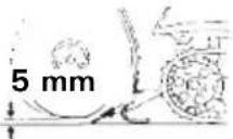 | |
| Clearing of hard, compact snow | UPPER | Upper position | Upper position | 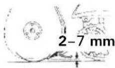 |
| Clearing of snow covering uneven ground | LOWER Upper | position | Lower position | 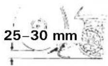 |
Skid
Adjust the skid for the auger housing ground clearance best suited to your snow removal conditions.
▲WARNING
To prevent accidental starting, turn the engine switch to the OFF position and disconnect the spark plug cap.
- Place the snowblower on a level surface and set the height adjusting bolts in the middle position. (Track type only)
- Loosen the bolts and adjust the skid and scraper height according to the road surface condition.
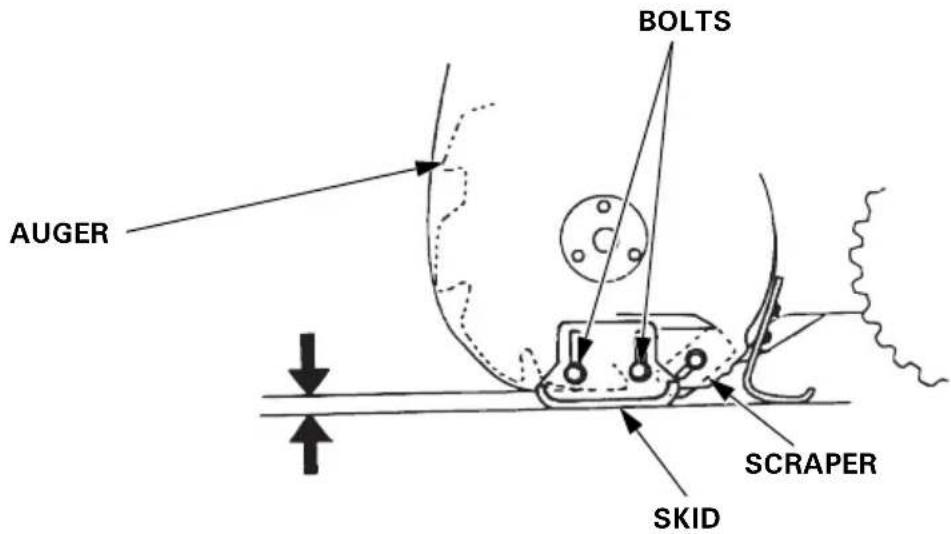
For use on uneven surfaces, lower the skid up to the bottom to obtain the maximum scraper ground clearance.
Factory pre-set clearance:
At the scraper: 3.0–7.0 mm (0.12–0.28 in)
At the auger: 8.0–12.0 mm (0.31–0.47 in)
NOTE:
- Adjust the skid equally on both sides.
- Be sure to tighten the skid and scraper bolts securely after making adjustment.
CAUTION:
Do not use the snowblower on rough or uneven surfaces with the auger ground clearance set for hard snow or surfaces.
This may cause serious damage to the snow blowing mechanism.
Operation
▲WARNING
Before operating this equipment you should read and understand the SAFETY INSTRUCTIONS on page 3 through 8.
- Start the engine according to the procedures described in page 29.
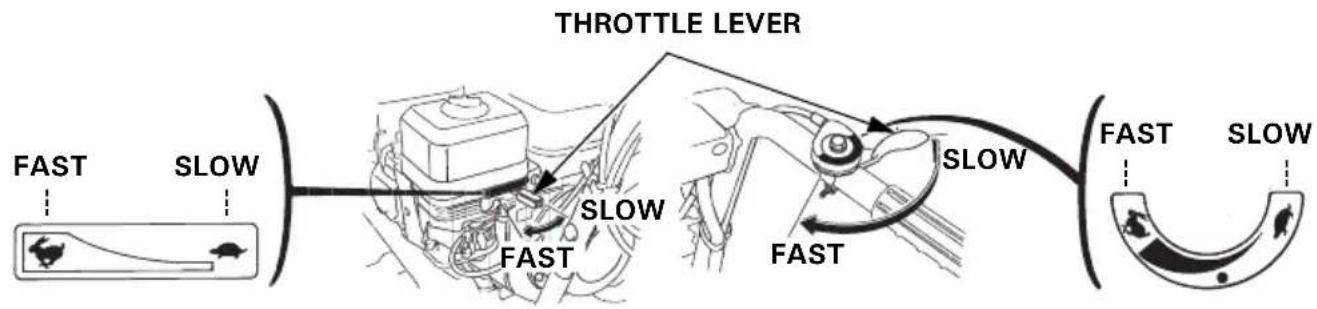
- Move the throttle lever to the FAST position for normal operation.
(HT, HTS, TC, TCS) (ET, ETS, EW, LW)
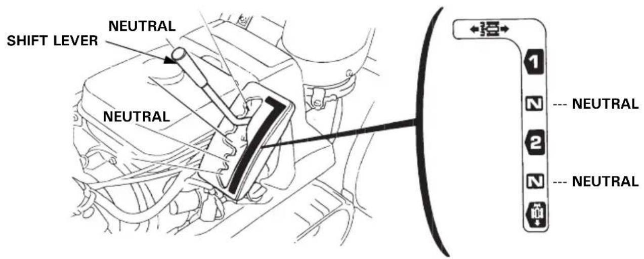
- Move the shift lever to select the desired drive speed.
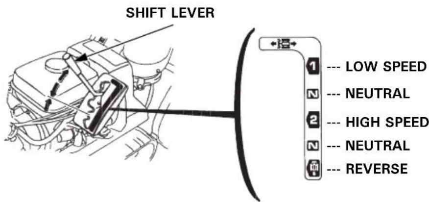
CAUTION:
- Be sure to disengage the drive clutch before shifting gears.
- Be sure to set the shift lever into the groove.
- Never move the shift lever while the snowblower is in motion.
NOTE: Low speed (1) is recommended for removing deep or hard-packed snow.
(Drive speed with throttle lever in the fast position)
| Shift lever position | Wheel type |
| EW, LW | |
| 1 | 0.30 m/s (0.97 ft/s) |
| 2 | 0.72 m/s (2.36 ft/s) |
| R | 0.72 m/s (2.36 ft/s) |
| Shift lever position | Track type | ||
| HT, HTS ET, ETS | TCS | ||
| 1 | 0.37 m/s (1.21 ft/s) 0.34 m/s (1.12 ft/s) 0.19 m/s (0.62 ft/s) | ||
| 2 | 0.88 m/s (2.89 ft/s) 0.85 m/s (2.79 ft/s) 0.47 m/s (1.54 ft/s) | ||
| R | 0.85 m/s (2.79 ft/s) 0.85 m/s (2.79 ft/s) 0.47 m/s (1.54 ft/s) | ||
Speed is stated in meters/second and (feet/second).
- Adjust the snow discharge chute guide according to the discharge angle and distance as required.
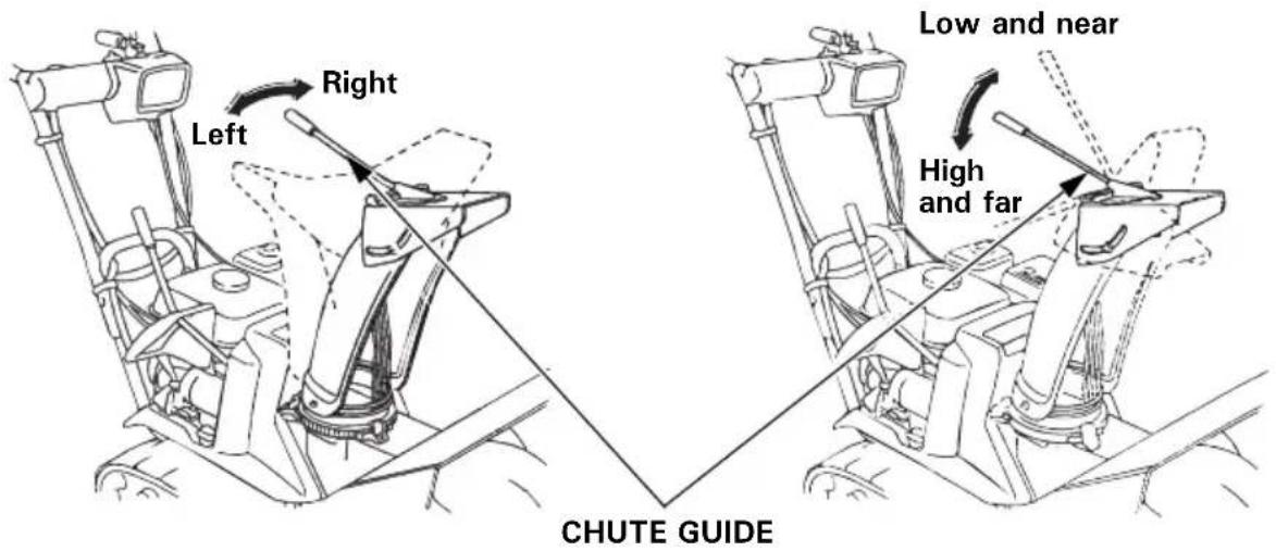
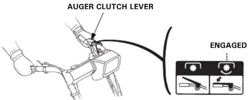
- The machine will run and clear snow simultaneously when you squeeze the auger clutch lever.
- To move from one place to another, or to change direction, use the drive clutch lever only.
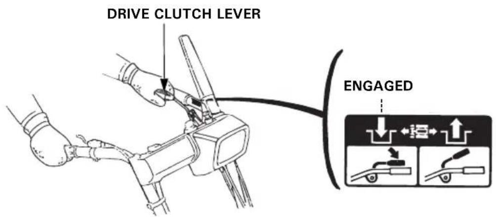
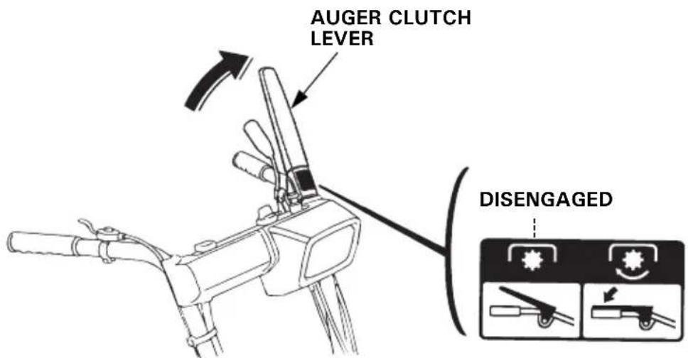
- To engage the auger clutch, first set the shift lever in the NEUTRAL position, then squeeze the auger clutch lever.
- Release your hand from the auger clutch lever to stop clearing or moving.
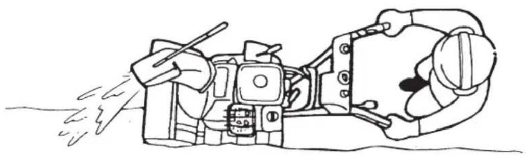
Clearing snow
For best efficiency, clear snow before it melts, refreezes and hardens. Do not reduce engine speed while throwing snow. Observe the following to clear hard or deep snow.
- Clearing in narrow width
Clear snow in 1st gear and in narrow width by using part of the snow blowing mechanism when the snow is deep or hardens.
natural_image
Line drawing of a person operating a mechanical device with a tool, emitting exhaust smoke (no text or symbols)- Intermittent clearing
Follow the steps described below when the engine lugs against deep or heavy snow.
-
Move the auger clutch lever to STOP.
-
Move the shift lever to NEUTRAL.
-
Squeeze the auger clutch lever to rotate the auger only.
-
Return the auger clutch lever to STOP after the engine picks up speed.
-
Move the shift lever to the desired position, then squeeze the auger clutch lever.

natural_image
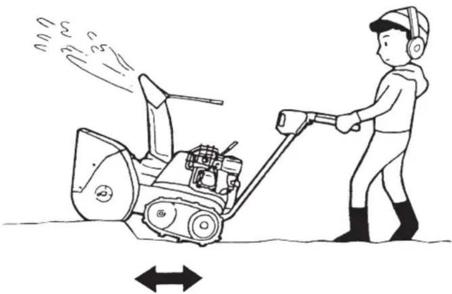
Line drawing of a person operating a snowman lawn tool, no text or symbols present- Clearing with back and forth motions If the snow is so hard that the snowblower tends to ride over the surface, push it back and forth to remove snow gradually.
natural_image
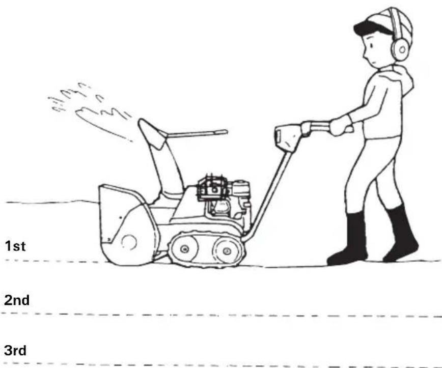
Illustration of a person using a snowman to lift a lawn mower, with motion arrows indicating speed (no text or symbols)- Clearing in steps If the height of the snow is greater than the height of the snow blowing mechanism, remove it in several steps as shown.
▲WARNING
- Adjust the snow discharge chute to avoid hitting the operator, bystanders, windows, and other objects with thrown snow. Stay clear of the snow discharge chute while the engine is running.
- If the snow discharge chute becomes clogged, stop the engine and use a snow drop bar or a wooden stick to unclog it.
Never put your hand into the snow discharge chute while the engine is running; serious personal injury could result. - To move from one place to another, or to change direction, use the drive clutch lever. Using the auger clutch lever will cause the snow blowing mechanism to rotate, possibly resulting in equipment damage or personal injury.
CAUTION:
- Never move the shift lever while the snowblower is in motion. Be sure to disengage the drive clutch or auger clutch before shifting gears.
- Be sure to set the shift lever into the groove.
Do not set in between the grooves.
• In an emergency:
Turn the engine switch to the OFF position.
(ET, EW, TC)
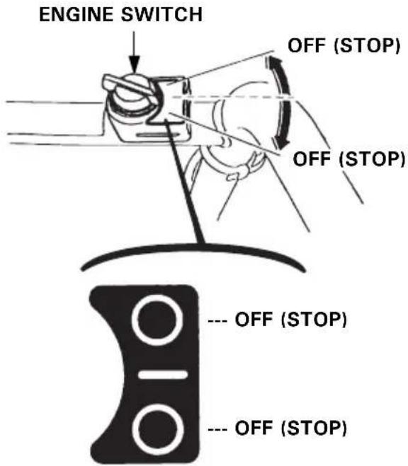
(HT, LW, TCS)
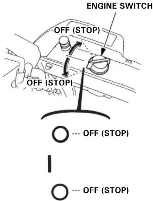
(ETS, HTS)
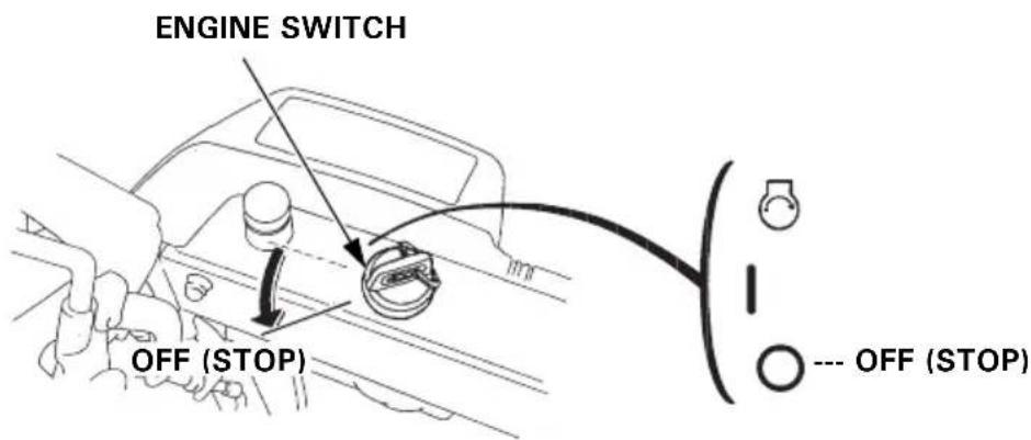
- At normal use:
(1) Release the auger clutch lever.
(2) Move the drive clutch lever to the STOP (DISENGAGED) position.
(3) Move the shift lever to the NEUTRAL position.
(4) Move the throttle lever to the SLOW position.
(5) Turn the engine switch to the OFF position.
ETS and HTS types:
Remove the key.
(6) Turn the fuel valve to the OFF position.
Periodic inspection and maintenance will help extend the service life of your snowblower while keeping it in the best operating condition. Inspect or service as described in the table on next page.
▲WARNING
- Shut off the engine before performing inspection and maintenance, and disconnect the spark plug cap from the plug so the engine cannot be started.
- If the engine must be run, make sure the area is well-ventilated. Exhaust gas contains poisonous carbon monoxide; exposure can cause loss of consciousness and may lead to death.
CAUTION:
- To avoid overturning, place the snowblower on a level surface before performing inspection and maintenance.
- Use only genuine Honda parts or their equivalent.
Replacement parts which are not of equivalent quality may damage the snowblower.
Maintenance schedule
| REGULAR SERVICE PERIOD (3)Perform at every indicatedmonth or operating hour interval,whichever comes first. | Each use | First month or 20 hrs. | Every year Every | 5 years | ||
| Before operation | Before storage | |||||
| Item | ||||||
| Engine oil Check level o | ||||||
| Change o o (1) | ||||||
| Transmission oil Check level o (2) | ||||||
| Battery electrolyte(If applicable) | Check o | |||||
| Charge o (1) (2) | o (1) (2) | |||||
| Spark plug Check-adjust o (1) | ||||||
| Replace o | (Every 250 hrs.) | |||||
| Auger skid shoes and scraper | Check-adjust o | o (1) | ||||
| Track | Check-adjust o (1) | |||||
| Wheel | Check o | o | ||||
| Auger and blower lock bolt | Check o | |||||
| Bolts, Nuts, Fasteners | Check o | |||||
| Fuel sediment cup | Clean | o | ||||
| Fuel tank and carburetor | Drain | o | ||||
| Anti corrosion oil | Apply oil | o | ||||
| Drive clutch cable | Check-adjust | o (1) (2) | ||||
| Auger clutch cable | Check-adjust | o (1) (2) | ||||
| Throttle cable | Check-adjust | o (1) (2) | ||||
| Idle speed | Check-adjust o (2) | |||||
| Valve clearance | Check-adjust o (2) | |||||
| Combustion chamber | Clean | After every 250 hrs. (2) | ||||
| Fuel tank and filter | Clean | o (2) | ||||
| Fuel tube | Check | Every 2 years (Replace if necessary) (2) | ||||
(1) These parts may require more frequent inspection and replacement under heavy use.
(2) These items should be serviced by your servicing dealer, unless you have the proper tools and are mechanically proficient. Refer to Honda shop manual for service procedures.
(3) For professional commercial use, log hours of operation to determine proper maintenance intervals.
Tools
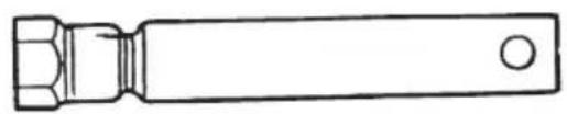
natural_image
Simple line drawing of a mechanical component with no text or symbolsSPARK PLUG WRENCH

WRENCH HANDLE
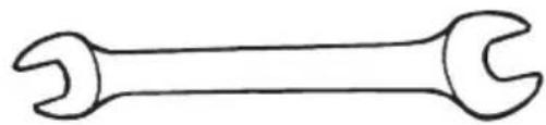
natural_image
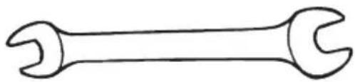
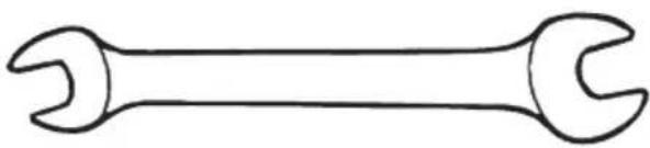
Simple line drawing of a double-ended wrench (no text or symbols)10×12 mm WRENCH
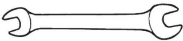
natural_image
Simple line drawing of a double-ended wrench (no text or symbols)10×14 mm WRENCH
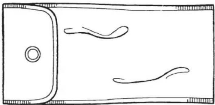
natural_image
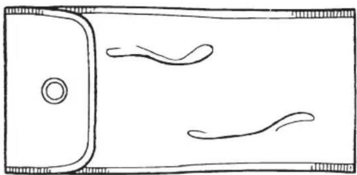
Top-down line drawing of a smartphone with two curved lines on the sides (no text or symbols)TOOL BAG
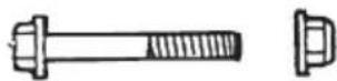
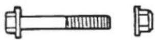
SPARE AUGER BOLT SET
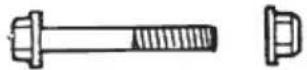
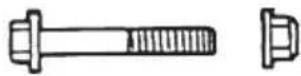
TWO 6×35 mm BOLTS
TWO 6 mm LOCK NUTS
Engine oil change
If the engine oil is dirty, engine wear will occur more rapidly. Change the oil at designated intervals. Maintain the oil at the proper level.
OIL CHANGE INTERVAL: Every year, before operation.
RECOMMENDED OIL: Use oil of API service classification SE or later, SAE 5W-30.
QUANTITY SPECIFIED: 0.58 L (0.61 US qt, 0.51 Imp qt)
How to change the oil:
- Place the snowblower on a level surface. Remove the oil filler cap/dipstick, the drain bolt and sealing washer.
Drain the oil while the engine is still warm to assure rapid and complete draining. - Reinstall the drain bolt and new sealing washer, and tighten the drain bolt securely.
CAUTION:
If you drain the oil immediately after stopping the engine, its temperature will be high and may cause burns.
3.(ETS and HTS types)
Fill with new oil up to the upper limit, as indicated by the oil filler cap/dipstick. (In checking the oil level with the oil filler cap/dipstick, do not screw the cap/dipstick in.) (See page 27)
(ET, HT, EW, LW, TC and TCS types)
Fill with new oil up to the upper limit.
- After replacing the oil, securely tighten the oil filler cap/dipstick.
Wash your hands with soap and water after handling used oil.
(ETS, HTS) (ET, HT, EW, LW, TC, TCS)
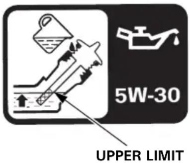
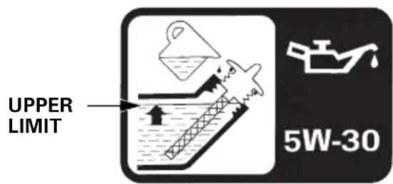
NOTE:
Please dispose of used motor oil in a manner that is compatible with the environment. We suggest you take it in a sealed container to your local service station for recycling. Do not throw in the trash or pour it onto the ground.
Spark plug—cleaning and adjustment
The spark plug must be periodically cleaned and adjusted to provide reliable ignition.
INTERVAL AT WHICH THE SPARK PLUG MUST BE CLEANED: Every year, before operation.
CLEANING PROCEDURE:
WARNING
If the engine has been running, the muffler will be very hot. Be careful not to touch the muffler while it is hot.
To ensure proper engine operation, the spark plug must be properly gapped and free of deposits.
- Remove the spark plug cap.
2.Clean any dirt from around the spark plug base. - Use the wrench supplied in the tool kit to remove the spark plug.
- Visually inspect the spark plug. Discard the spark plug if there is apparent wear, or if the insulator is cracked or chipped. Clean the spark plug with a wire brush if it is to be reused.
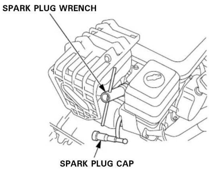
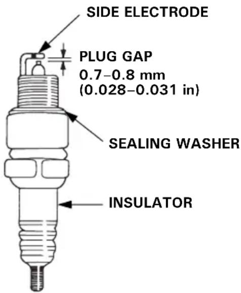
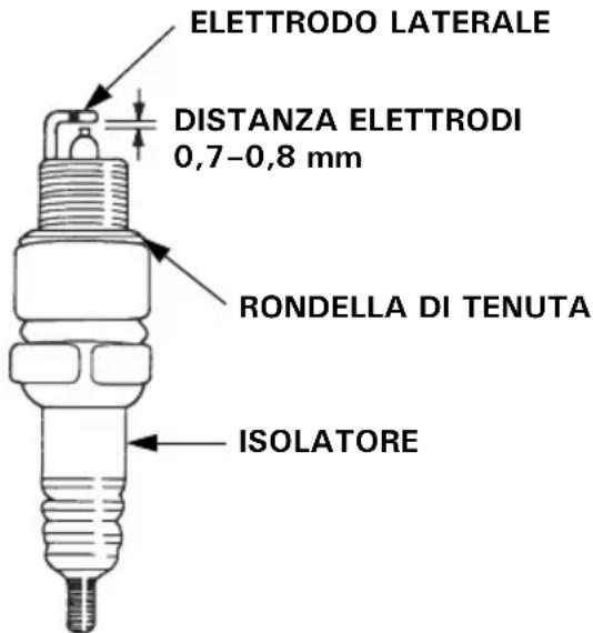
- Measure the plug gap with a feeler gauge.
Correct as necessary by carefully bending the side electrode.
The gap should be:
0.7–0.8 mm (0.028–0.031 in)
Recommended spark plug: BPR5ES (NGK)
W16EPR-U (DENSO)
- Make sure that the sealing washer is in good condition and thread the spark plug in by hand to prevent cross-threading.
- After the spark plug is seated, tighten with a spark plug wrench to compress the washer.
NOTE:
If installing a new spark plug, tighten 1/2 turn after the spark plug seats to compress the washer. If reinstalling a used spark plug, tighten 1/8 to 1/4 turn after the spark plug seats.
CAUTION:
- Use only the recommended spark plugs or equivalent plugs. Spark plugs which have an improper heat range may cause engine damage.
- The spark plug must be securely tightened. An improperly tightened spark plug can become very hot and may damage the engine.
Track-adjustment (track type only)
ADJUSTMENT INTERVAL: Every year, before operation
Make sure the tracks are clean and dry before adjustment. The tracks cannot be correctly adjusted if clogged with snow or debris, or coated with ice.
With the snowblower resting on its tracks, check track deflection by pressing down midway between the wheels with a force of 15 kgf (33 lbf).
When correctly adjusted, track deflection should be:
25.0-30.0 mm (0.98-1.18 in)
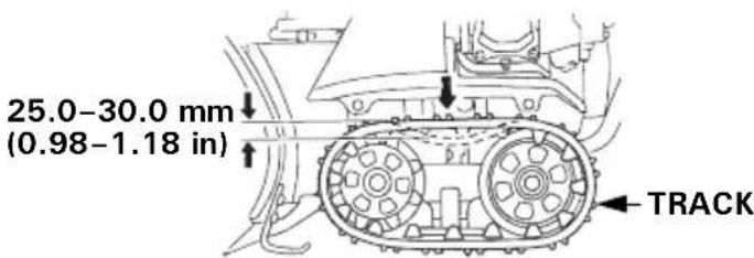
Adjusting procedure:
- Loosen the left and right tension bolt lock nuts at the rear axle, and turn the adjusting nuts to correctly tension both tracks.
- After adjustment, tighten the lock nuts securely.
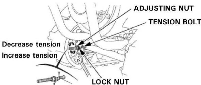
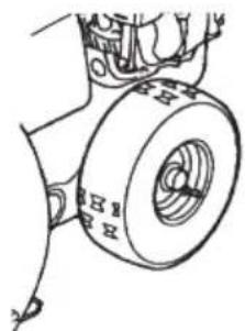
Tires (wheel type only)
CAUTION:
- Do not operate with a flat tire. This may cause the bead to come off.
- Over inflation can cause premature tire failure. Inflate the tires to manufacturer's recommended tire pressure.
Before each use, check the tire pressure with an air pressure gauge.
Pressure:
80\~100 kPa (0.8\~1.0 kgf/cm², 11.4\~14 psi)
natural_image
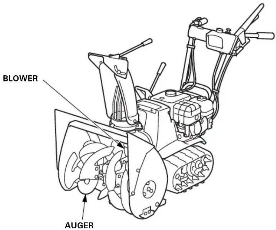
Technical line drawing of a mechanical component with no visible text or symbolsCheck auger, blower, and bolts nuts and fasteners:
Check the following points to ensure safe, reliable operation every year before operation.
- Nuts, bolts and screws: Check for tightness.
- Snowthrowing components: Check to see that the auger and the blower are in good condition.
- If there are any problems, see your authorized Honda dealer.
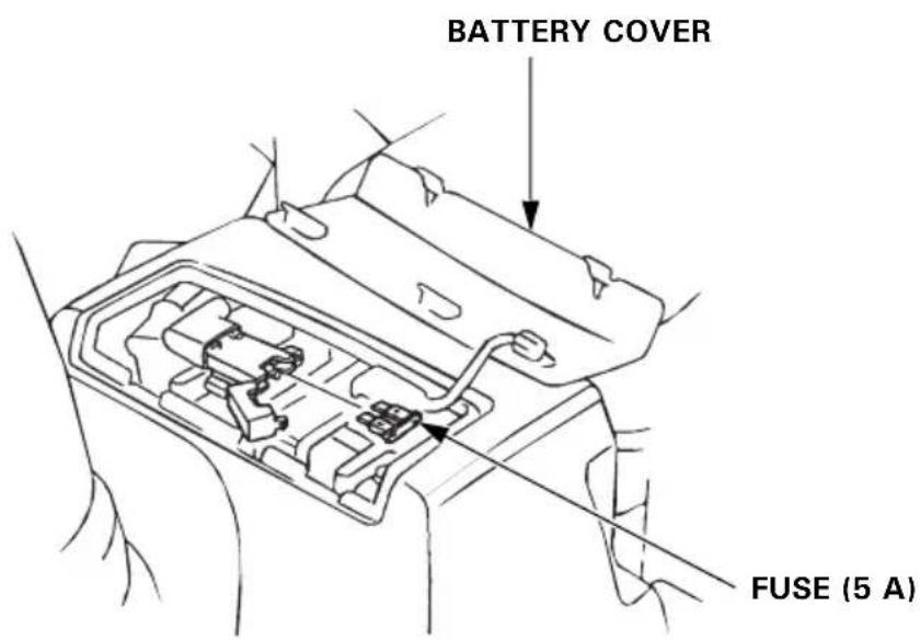
Fuse (ETS, HTS)
In the event of blower fuse, replace it with another fuse of the rated capacity only after investigating the cause for the failure. If the fuse is replaced without correcting cause, the new fuse may blow quickly again.
CAUTION:
Never replace a blown fuse with any object other than another fuse of the rated capacity. Using any other object such as wire or aluminum foil may cause fires in wiring or other parts.
Fuse-replacement
- Remove the battery cover.
- Replace the fuse as shown in the illustration.
Battery removal/installation (ETS, HTS)
▲WARNING
- Batteries produce explosive gases: If ignited, an explosion can cause serious injury or blindness. Provide adequate ventilation when charging.
- CHEMICAL HAZARD: Battery electrolyte contains sulfuric acid. Contact with eyes or skin, even through clothing, may cause severe burns. Wear a faceshield and protective clothing. Keep flames and sparks away, and do not smoke in the area.
-
ANTIDOTE: If electrolyte gets into your eyes, flush throughly with warm water for at least 15 minutes and call a physician immediately. POISON: Electrolyte is poison.
• ANTIDOTE: -
External: Flush throughly with water.
- Internal: Drink large quantities of water or milk.
Follow with milk of magnesia or vegetable oil, and call a physician immediately.
- KEEP OUT OF REACH OF CHILDREN.
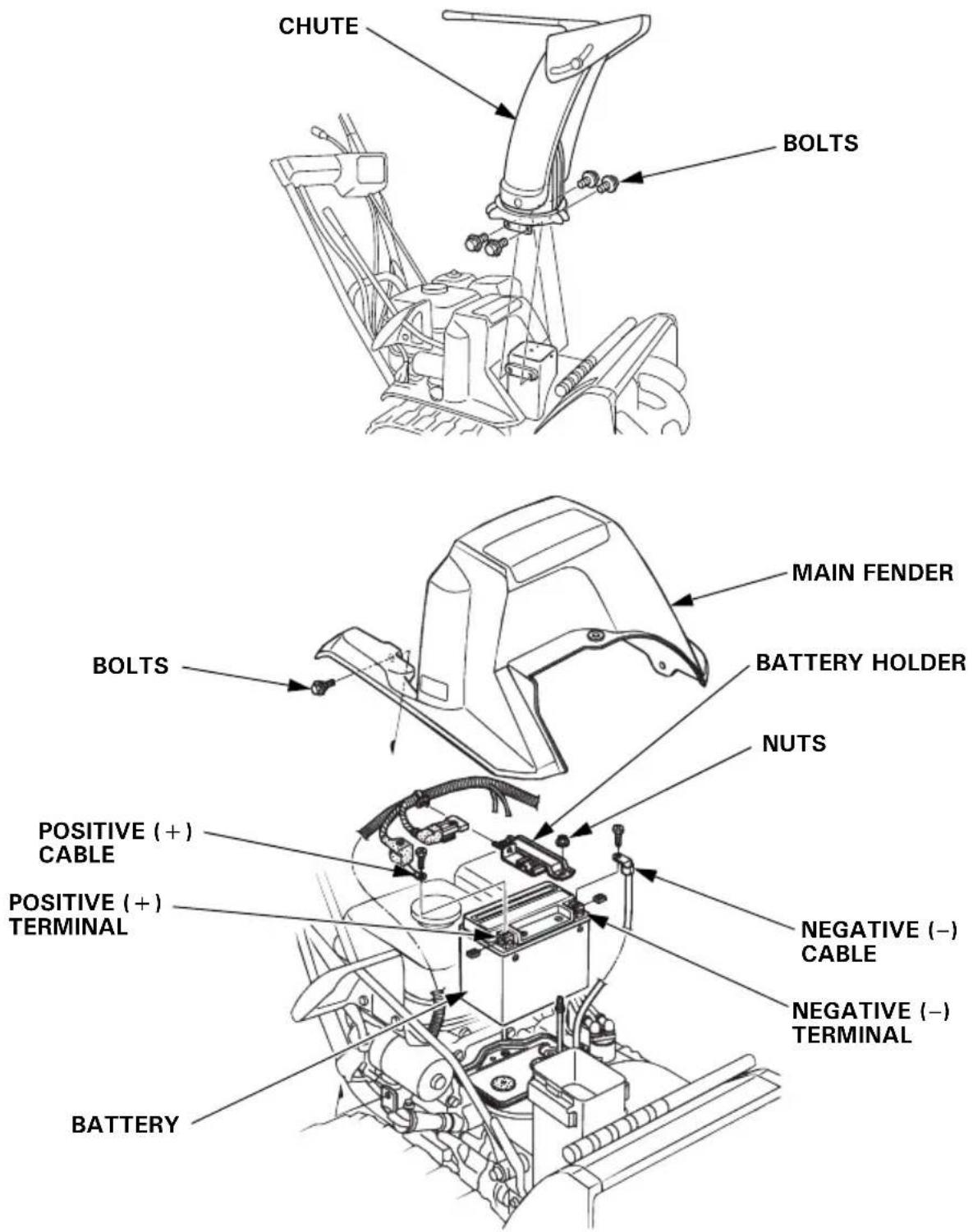
Battery removal:
- Remove the chute.
- Remove the main fender.
- Disconnect the negative (−) cable from the battery negative (−) terminal; then disconnect the positive (+) cable from the battery positive (+) terminal.
- Loosen the nuts, and pull off the battery holder from the battery.
Battery installation:
- Set the battery.
- Set the battery holder and tighten the nuts.
- Connect the positive (+) cable to the battery positive (+) terminal, then connect the negative (−) cable to the battery negative (−) terminal.
- Reinstall the main fender.
- Reinstall the chute.
[TRACK TYPE]
CAUTION:
When disconnecting the battery cable, be sure to disconnect at the battery negative (−) terminal first. To connect, connect at the battery positive (+) terminal first, then at the battery negative (−) terminal. Never disconnect the battery cable in the reverse order, or it causes a short circuit when a tool contacts the terminals.
Battery servicing
Recharge the battery every 6 months if it is to be stored for an extended period of time after the season. Check the battery and recharge it before putting the snowblower into service after long outage.
For suitable battery charger, consult your authorized Honda dealer.
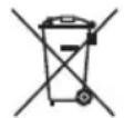
This symbol on the battery means that this product must not be treated as household waste.
NOTE:
An improperly disposed of battery can be harmful to the environment and human health.
Always confirm local regulations for battery disposal.
Before storing the snowblower for an extended period:
- Be sure the storage area is free of excessive humidity and dust.
- Make sure that the engine switch is in the OFF position.
- Drain the fuel.
▲WARNING
- Gasoline is extremely flammable and explosive under certain conditions. Do not smoke or allow flames or sparks in the area.
- Do not drain the fuel tank when the exhaust system is hot.
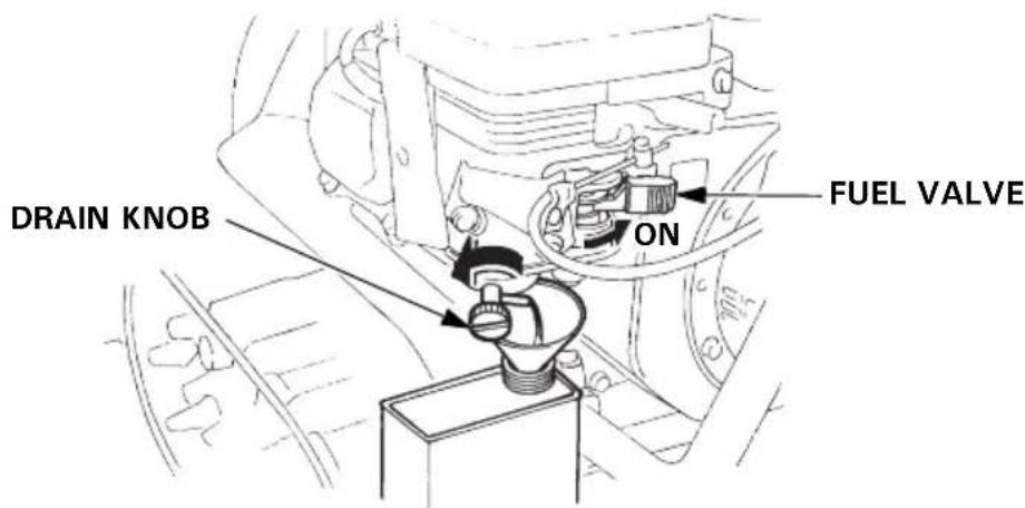
a. Turn the fuel valve ON.
b. Loosen the carburetor drain knob, and drain the gasoline into a suitable container. After draining, retighten the drain knob and turn the fuel valve OFF.
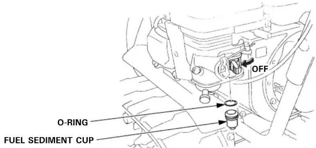
- Clean the fuel sediment cup.
a. Turn the fuel valve to the OFF position, remove the fuel sediment cup, and clean it in clean solvent.
b. Reinstall the O-ring and fuel sediment cup and tighten it securely.
- Remove the spark plug and pour three tablespoonsful of clean motor oil into the cylinder. Pull the starter grip slowly two or three times to distribute the oil.
Reinstall the spark plug. - Pull the starter grip until resistance is felt. This closes the valves and protects the engine from internal corrosion.
Apply oil to the following parts for lubrication and rust prevention.
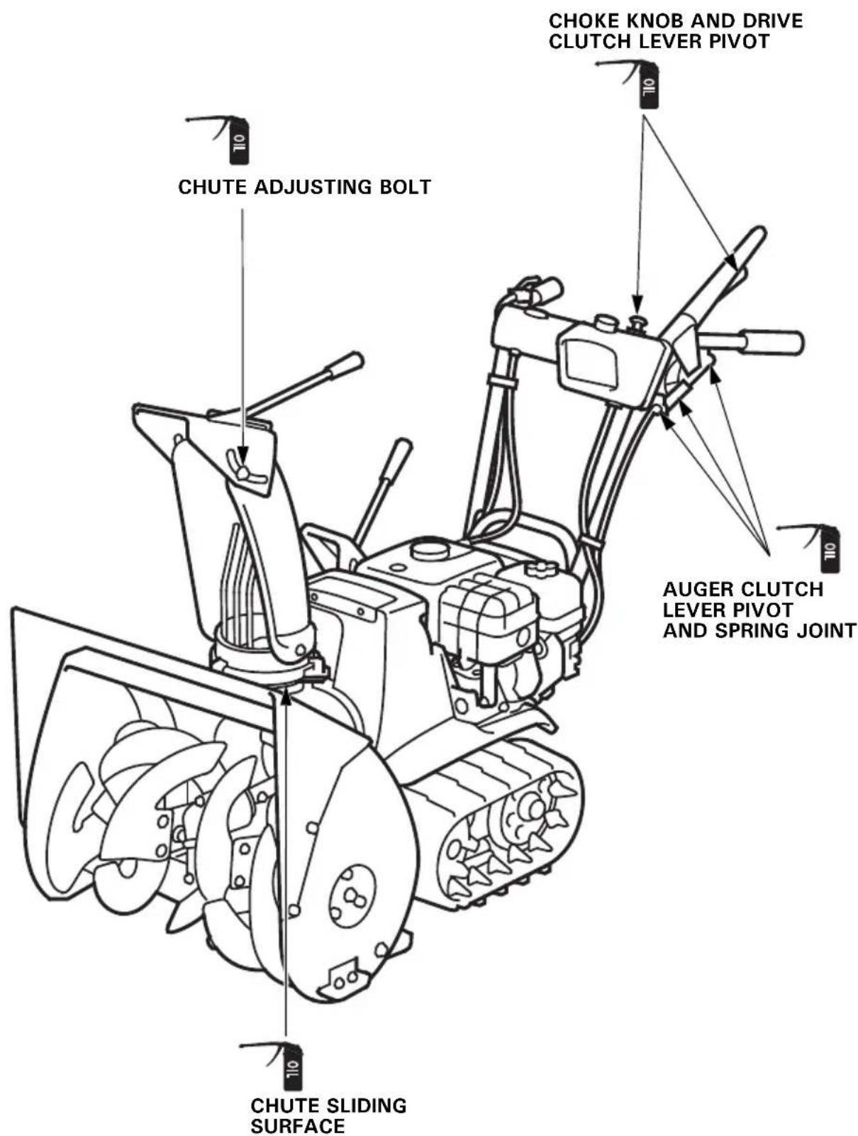
When the engine will not start:
1.Is there enough fuel?
2.Is the fuel valve on?
3.Is gasoline reaching the carburetor?
To check, loosen the drain knob with the fuel valve on. Fuel should flow freely.
▲WARNING
Gasoline is extremely flammable, and gasoline vapor can explode. If any fuel is spilled, make sure the area is dry before starting the engine. Spilled fuel or fuel vapor may ignite.
4.Is the engine switch on?
5. Check the spark plug for dirt, wet and the gap.
a. Clean the spark plug.
b. Reinstall the plug if it is reused, or replace with a new one.
- If the engine still does not start, take the snowblower to an authorized Honda dealer.
When the auger does not operate:
Check the auger lock bolts and replace if broken off with the wrench handle.
Secure the auger lock bolts with 6 mm nuts.
Spare auger lock bolts and nuts are supplied with the snowblower.
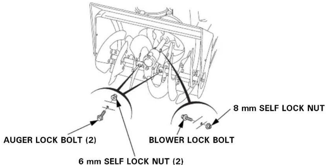
When the blower does not operate:
Check the blower lock bolt and replace if broken off with the wrench handle.
Secure the blower lock bolt with 8 mm nut.
A new blower lock bolt and nut are available from authorized Honda dealer.
| Model HSS622 HSS655 | ||
| Description code SBFJ SBHJ |
Engine
| Model GX160 | |
| Engine Net power(in accordance with SAE J1349*) | 3.6 kW (4.9 PS)/3,600 rpm |
| Displacement 163 cm | ^3 (9.9 cu-in) |
| Bore × stroke 68.0 × 45.0 mm | (2.7 × 1.8 in) |
| Starting method Recoil starter, | Recoil or electric starter |
| Ignition system Transistor magneto | |
| Oil capacity 0.58 L (0.61 US qt, 0.51 lmp qt) | |
| Fuel tank capacity 3.1 L (0.82 US gal, 0.68 lmp gal) | |
| Spark plug BPR5ES (NGK), W1 | 6EPR-U (DENSO) |
| Battery (equipped type) 12 V 1 | 0 Ah/10 HR |
*The power rating of the engine indicated in this document is the net power output tested on a production engine for the engine model and measured in accordance with SAE J1349 at 3,600 rpm (Engine Net Power). Mass production engines may vary from this value. Actual power output for the engine installed in the final machine will vary depending on numerous factors, including the operating speed of the engine in application, environmental conditions, maintenance, and other variables.
Frame
| TypeItems | Track type Wheel type | ||||
| TC TC | S ET, HT | ETS, HTS | EW, LW | ||
| *Overall length | 1,460 mm (57.5 in) | 1,500 mm (59.1 in) | 1,400 mm (55.1 in) | ||
| Overall width | 550 mm (21.7 in) | ||||
| Overall height | 1,125 mm (44.3 in) | 1,110 mm (43.7 in) | |||
| *Dry mass [weight] | 65 kg(143 lbs) | 70 kg(154 lbs) | 70 kg(154 lbs) | 75 kg(165 lbs) | 65 kg (143 lbs) |
| Width of snow clearance | 550 mm (21.7 in) | ||||
| Height of snow clearance | 420 mm (16.5 in) | 500 mm (19.7 in) | |||
| Snowthrowing distance(differs according to thekind of snow) | Max. 14 m (45.9 ft) | ||||
| Clearing capacity | 35 tons/hour 37 | tons/hour 32 tons/hour | |||
| Continuous operating time(differs according to thekind of snow) | 2.7 hours | ||||
*: The values of overall length and dry mass [weight] differ depending upon the type of unit.
Noise and Vibration
| Sound pressure level at operator's ears(EN ISO 11200: 1995) | 85 dB (A) |
| Uncertainty 2 dB (A) | |
| Measured sound power level(2000/14/EC, 2005/88/EC) | 98 dB (A) |
| Uncertainty 2 dB (A) | |
| Guaranteed sound power level(2000/14/EC, 2005/88/EC) | 100 dB (A) |
| Vibration level at hand arm(EN1033: 1995) | 9.5 m/s^2 |
| Uncertainty(EN12096: 1997 Annex D) | 3.8 m/s^2 |
Tune-Up
| ITEM SPECIFICATION MAINTENANCE | ||
| Spark plug gap 0.7–0.8 mm(0.028–0.031 in) | Refer to page 50 | |
| Valve clearance IN: 0.08 ±0.02 mm (cold)EX: 0.10 ±0.02 mm (cold) | See your authorized Honda dealer | |
| Other specification No other adjustment needed. | ||
Specifications are subject to change without notice.
MEMO
MEMO
MEMO
MANUEL DU PROPRIÉTAIRE
Notice originale

SPEC
ECOLOGY CONSCIOUS TECHNOLOGY
natural_image
Illustration of a person operating a snowman in a field, no text or symbols presentATTENTION
natural_image
Illustration of a snowman, a child, and a dog near a fence with a bulldozer (no text or symbols)ATTENTION
natural_image
Line drawing of a snowman lawn tool with visible blades and wheels (no text or symbols)NUMÉRO DE SÉRIE DU CADRE*
(ET, EW, TC) (HT, LW, TCS) (ETS, HTS)
natural_image
Technical line drawing of a mechanical assembly with no visible text or symbolsBOUTON DU DÉMARREUR
Bouton du starter
(ET, EW, TC) (HT, LW, TCS) (ETS, HTS)
natural_image
Mechanical diagram showing a lever mechanism with arrows indicating motion direction (no text or symbols)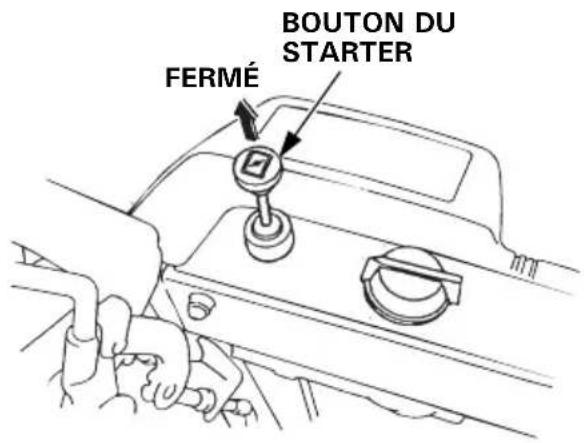
(ETS, HTS) (TC, TCS)
BOUTON DU
FERMÉ STARTER
natural_image
Line drawing of a car interior showing hand positioning and valve mechanism (no text or symbols)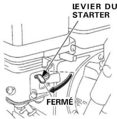
[UNIQUEMENT DÉMARRAGE MANUEL]
natural_image
Technical line drawing of a vehicle's internal components and suspension system (no text or symbols)PRECAUTION :
natural_image
Line drawing of a person operating a mechanical device with a tool, emitting exhaust smoke (no text or symbols)natural_image
Line drawing of a person operating a small utility tool with a head covering, emitting exhaust smoke (no text or symbols)natural_image
Illustration of a person using a snowman to lift a lawn mower, with motion arrows indicating speed (no text or symbols)natural_image
Simple line drawing of a cylindrical object with a flanged end and a circular hole at the top (no text or symbols)CLÉ À BOUGIE
JEU DE BOULONS DE RECHANGE POUR FRAISE
DEUX BOULONS 6 × 35 mm

TIGE
DEUX CONTRE-ÉCROUS 6 mm
natural_image
Simple line drawing of a double-ended wrench (no text or symbols)CLÉ 10 × 12 mm
natural_image
Simple line drawing of a double-ended wrench (no text or symbols)CLÉ 10 × 14 mm
natural_image
Simple line drawing of a smartphone with two curved lines on the sides (no text or symbols)SAC À OUTILS
(ETS, HTS) (ET, HT, EW, LW, TC, TCS)
REMARQUE :
natural_image
Technical line drawing of a mechanical component with no visible text or symbolsECOLOGY CONSCIOUS TECHNOLOGY
natural_image
Illustration of a person operating a small utility pole with a tool, no text or symbols present▲WARNUNG
natural_image
Cartoon illustration of a snowman, a child, and a dog near a fence with a bulldozer (no text or symbols)AWARNUNG
natural_image
Line drawing of a snowman lawn tool with visible blades and wheels (no text or symbols)RAHMENSERIENNUMMER*
(ET, EW, TC) (HT, LW, TCS) (ETS, HTS)
Kraftstoffhahn
(ET, EW, TC) (HT, LW, TCS) (ETS, HTS)
MOTORSCHALTER MOTORSCHALTER
O
(ETS, HTS) (TC, TCS)

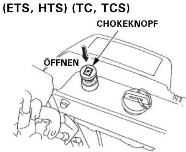
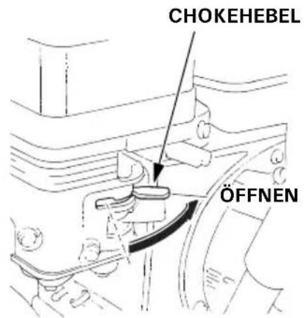
[Gleichstrom-Elektrostart] (ETS, HTS)
natural_image
Technical line drawing of a vehicle's lower body and suspension system, showing mechanical components and wiring (no text or labels)Am Schaber: 3,0–7 ,0 mm
natural_image
Line drawing of a person operating a mechanical device with a tool, no text or symbols presentnatural_image
Line drawing of a person using a snowman lawn tool, no text or symbols presentnatural_image
Illustration of a person pushing a snowman with motion lines indicating speed (no text or symbols)natural_image
Simple line drawing of a mechanical component with no text or symbolsZÜNDKERZENSCHLÜSSEL
natural_image
Simple line drawing of a double-ended wrench (no text or symbols)natural_image
Simple line drawing of a double-ended wrench (no text or symbols)natural_image
Simple line drawing of a smartphone with two curved lines on the sides (no text or symbols)WERKZEUGTASCHE
(ETS, HTS) (ET, HT, EW, LW, TC, TCS)
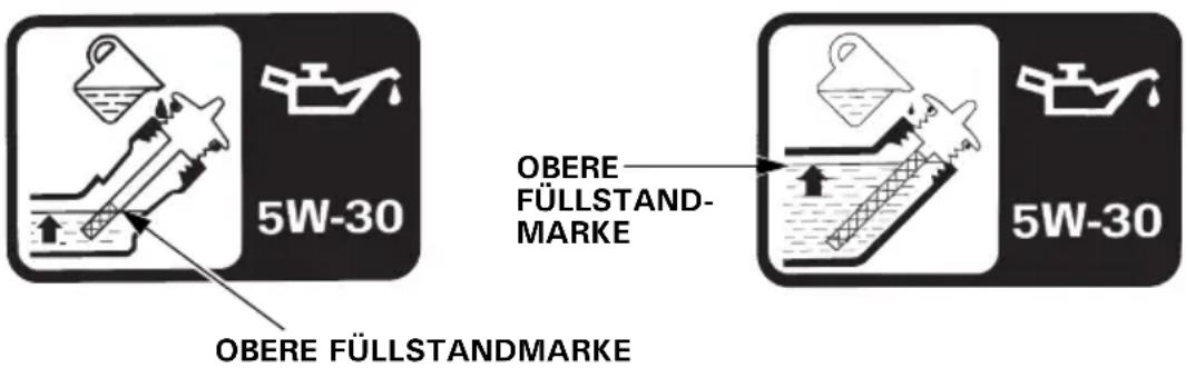
HINWEIS:
natural_image
Technical line drawing of a mechanical component with no visible text or symbolsECOLOGY CONSCIOUS TECHNOLOGY
natural_image
Illustration of a person operating a small utility pole next to a tractor, with no visible text or symbols.ATTENZIONE
natural_image
Illustration of a snowman, child, and dog near a fence with a utility pole and worker (no text or symbols)ATTENZIONE
natural_image
Line drawing of a snowman lawn tool with visible blades and wheels (no text or symbols)NUMERO DI SERIE DEL TELAIO*
(ET, EW, TC) (HT, LW, TCS) (ETS, HTS)
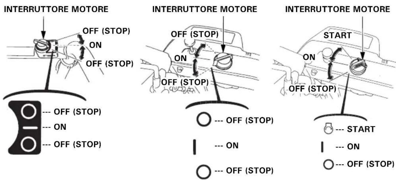
Valvola carburante
ATTENZIONE
natural_image
Technical line drawing of a mechanical assembly with no visible text or symbols(ET, EW, TC) (HT, LW, TCS) (ETS, HTS)
INTERRUTTORE MOTORE INTERRUTTORE MOTORE
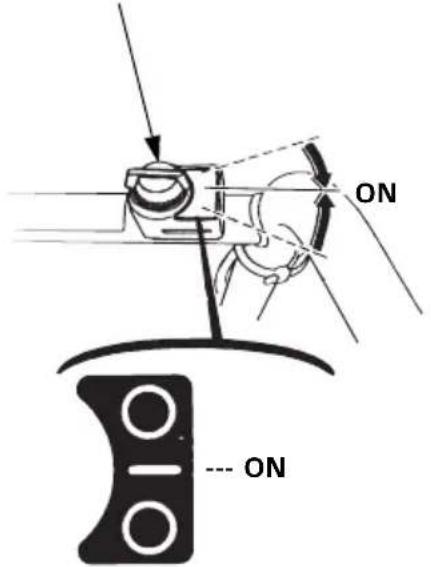
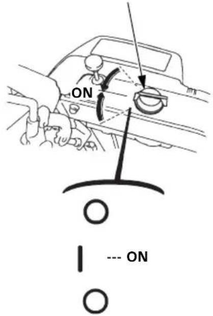
INTERRUTTORE MOTORE
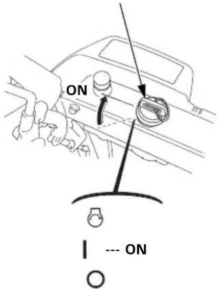
(ETS, HTS) (TC, TCS)
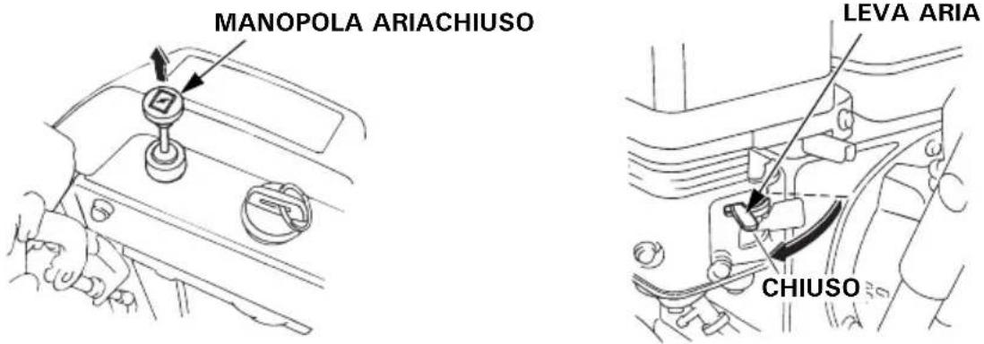
(ETS, HTS) (TC, TCS)
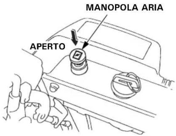
LEVA ARIA
natural_image
Technical line drawing of a vehicle's lower body and suspension system (no text or symbols)Sulla lama: 3,0–7 ,0 mm
Sulla coclea: 8,0–1 2,0 mm
NOTA:
natural_image
Line drawing of a person operating a mechanical device with a tool, emitting exhaust smoke (no text or symbols)• Sgombero intermittente
natural_image
Line drawing of a person operating a snowman lawn tool, no text or symbols presentnatural_image
Line drawing of a person using a snowman lawn tool, with motion arrows indicating speed (no text or symbols)natural_image
Simple line drawing of a mechanical component with no text or symbolsVITE SVITACANDELE
SET BULLONI DI
RICAMBIO COCLEA
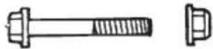

DUE BULLONI 6 × 35 mm

MANICO CHIAVE
DUE DADI DI
BLOCCAGGIO 6 mm
natural_image
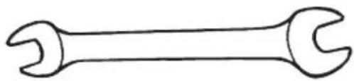
Simple line drawing of a double-ended wrench (no text or symbols)CHIAVE 10×12 mm
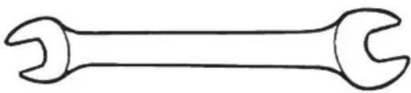
natural_image
Simple line drawing of a double-ended wrench (no text or symbols)CHIAVE 10×14 mm

natural_image
Top-down line drawing of a smartphone with two curved abstract shapes on the sides (no text or symbols)CASSETTA ATTREZZI
Cambio olio motore
(ETS, HTS) (ET, HT, EW, LW, TC, TCS)
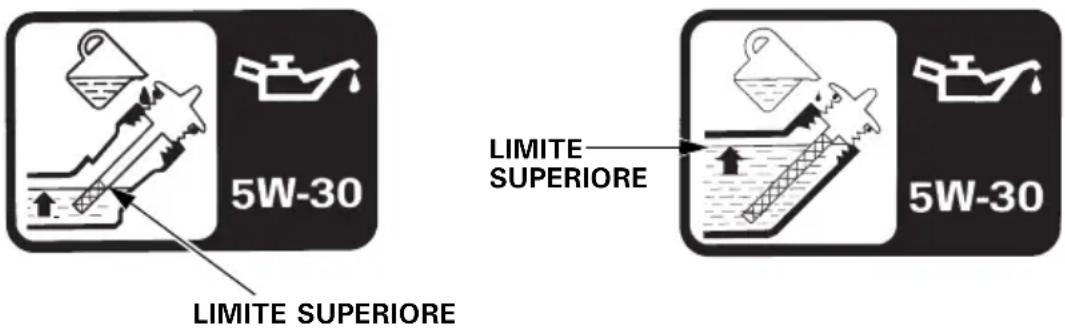
NOTA:
Candela consigliata: BPR5ES (NGK)
W16EPR-U (DENSO)
natural_image
Technical line drawing of a mechanical component with no visible text or symbols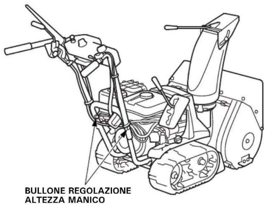
Fusibile (ETS, HTS)
For further information, please contact Honda Customer Information Centre at the following address or telephone number:
ADRESSES DES PRINCIPAUX DISTRIBUTEURS Honda
BALTIC STATES (Estonia/Latvia/ Lithuania)
Honda Motor Europe Ltd
Tulika 15/17
10613 Tallinn
Tel.:+372 6801 300
Fax: +372 6801 301

honda.baltic@honda-eu.com.
BELGIUM
Honda Motor Europe Ltd
Doornveld 180-184
1731 Zellik
Tel. :+32 2620 10 00
Fax: +32 2620 10 01
http://www.honda.be

BH_PE@HONDA-EU.COM
BULGARIA
Kirov Ltd.
49 Tsaritsa Yoana blvd 1324 Sofia
162, Yiannos Kranidiotis Avenue
2235 Latsia, Nicosia
Tel. :+357 22 715 300
Fax : +357 22 715 400
CZECH REPUBLIC
BG Technik cs, a.s.
U Zavodiste 251/8
15900 Prague 5 - Velka Chuchle
Tel. :+420 2 838 70 850
Fax: +420 2 667 111 45
http://www.honda-stroje.cz
DENMARK
TIMA A/S
Tårnfalkevej 16
2650 Hvidovre
Tel. :+45 36 34 25 50
M50 Business Park, Ballymount
Dublin 12
Tel. : + 353 1 4381900
Fax: +353 1 4607851
http://www.hondaireland.ie

Service@hondaireland.ie
ITALY
The Associated Motors
Company Ltd.
New Street in San Gwakkin Road
Afd, Power Equipment
Capronilaan 1
1119 NN Schiphol-Rijk
Tel. :+31 20 7070000
Fax: +31 20 7070001
http://www.honda.nl
NORWAY
Berema AS
P.O. Box 454
1401 Ski
Tel. :+47 64 86 05 00
Fax : +47 64 86 05 49
http://www.berema.no
berema@berema.no
POLAND
Aries Power Equipment Sp. z o.o.
ul. Wroclawska 25
01-493 Warszawa
Tel. : +48 (22) 861 43 01
Fax : +48 (22) 861 43 02
http://www.ariespower.pl
1, Pridirizhnaya Street, Sharapovo
settlement, Naro-Fominsky district,
Moscow Region, 143350 Russia
Tel.: +7 (495) 745 20-80
Fax: +7 (495) 745 20 81
www.honda.co.ru

postoffice@honda.co.ru
SERBIA & MONTENEGRO
BPP Ground d.o.o
Generala Horvatovica 68
11000 Belgrade
Tel. : +381 11 3820 295
Fax : +381 11 3820 296
http://www.hondasrbija.co.rs

honda@bazis.co.rs
SLOVAK REPUBLIC
Honda Motor Europe Ltd
Prievozská 6 821 09 Bratislava
Tel. :+421 2 32131112
Fax: +421 2 32131111
http://www.honda.sk
SLOVENIA
AS Domzale Moto Center D.O.O.
Blatnica 3A
1236 Trzin
Tel.: +386 1 562 22 62
Fax : +386 1 562 37 05
www.honda-as.com

Las Palmas province (Canary Islands)
Greens Power Products, S.L.
Poligono Industrial Congost -
Tenerife province (Canary Islands)
Slough - Berkshire, SL3 8QY
Tel. :+44 (0)845 200 8000
http://www.honda.co.uk
AUSTRALIA
Honda Australia Motorcycle and Power Equipment Pty. Ltd
1954-1956 Hume Highway
Campbellfield Victoria 3061
EC Declaration of Conformity
- The undersigned, Piet Renneboog, on behalf of the authorized representative, herewith declares that the machinery described below fulfils all the relevant provisions of:
• Directive 2006/42/EC on machinery
• Directive 2004/108/EC on electromagnetic compatibility
- Directive 2000/14/EC – 2005/88/EC on outdoor noise
- Description of the machinery
a) Generic denomination: Snow thrower
b) Function: removing snow
| c) Commercial name | d) Type | e) Serial number |
| *1 | *1 |
- Manufacturer
Honda Motor Co., Ltd. 2-1-1 Minamiaoyama Minato-ku, Tokyo, JAPAN
- Authorized representative and able to compile the technical documentation
Honda Motor Europe Ltd Belgian Branch p/a Honda Motor Europe Ltd – Aalst Office Wijngaardveld 1 (Noord V) B-9300 Aalst (Belgium)
| 5. References to harmonized standards | 6. Other standards or specifications |
| - | - |
- Outdoor noise Directive
a) Measured sound power dB(A): *1
b) Guaranteed sound power dB(A): *1
c) Noise parameter (kW/min ^-1 ): *1
d) Conformity assessment procedure: ANNEX V
c) Notified body: -
-
Done at: Aalst, BELGIUM
-
Date:
Piet Renneboog Homologation Manager Honda Motor Europe Ltd Belgian Branch p/a Honda Motor Europe Ltd – Aalst Office
- OWNER'S MANUAL
- MANUEL DE L'UTILISATEUR
- BEDIENUNGSANLEITUNG
- ▲WARNING
- Disposal
- WARNING
- Operator responsibilities
- NOTE:
- [TC and TCS types]
- CE mark and noise label locations
- Engine switch
- Fuel valve
- AC starter button (TCS)
- Choke knob
- Starter grip
- Throttle lever (engine speed)
- Shift lever
- Chute guide
- Drive clutch lever
- Snow drop bar
- Headlight switch (ETS, HTS, HT, LW, TCS)
- Auger clutch lever
- Height adjusting bolt (track type only)
- Handle height adjusting bolt
- Skid plate, scraper
- Skid
- Inspection:
- Refilling:
- CAUTION:
- GASOLINES CONTAINING ALCOHOL
- Engine oil level
- (ETS and HTS types)
- RECOMMENDED OIL:
- [AC Electric starting] (TCS)
- [MANUAL STARTING ONLY]
- [DC Electric starting] (ETS, HTS)
- Carburetor Modification for High Altitude Operation
- Factory pre-set clearance:
- Operation
- Clearing snow
- Tools
- Engine oil change
- How to change the oil:
- 3.(ETS and HTS types)
- Spark plug—cleaning and adjustment
- Track-adjustment (track type only)
- Adjusting procedure:
- Check auger, blower, and bolts nuts and fasteners:
- Fuse (ETS, HTS)
- Fuse-replacement
- Battery removal/installation (ETS, HTS)
- Battery removal:
- Battery installation:
- Battery servicing
- MANUEL DU PROPRIÉTAIRE
- ATTENTION
- Bouton du starter
- [UNIQUEMENT DÉMARRAGE MANUEL]
- PRECAUTION :
- REMARQUE :
- ▲WARNUNG
- AWARNUNG
- Kraftstoffhahn
- [Gleichstrom-Elektrostart] (ETS, HTS)
- HINWEIS:
- ATTENZIONE
- (ET, EW, TC) (HT, LW, TCS) (ETS, HTS)
- Valvola carburante
- NOTA:
- Cambio olio motore
- Fusibile (ETS, HTS)
- ADRESSES DES PRINCIPAUX DISTRIBUTEURS Honda
- BALTIC STATES (Estonia/Latvia/ Lithuania)
- BELGIUM
- BULGARIA
- CZECH REPUBLIC
- DENMARK
- ITALY
- NORWAY
- POLAND
- SERBIA & MONTENEGRO
- SLOVAK REPUBLIC
- SLOVENIA
- Las Palmas province (Canary Islands)
- Tenerife province (Canary Islands)
- AUSTRALIA
- EC Declaration of Conformity
Brand : Honda
Model : HSS 655 TD
Category : Snow blower