XR250 Tornado (2017) - Motorcycle Honda - Free user manual and instructions
Find the device manual for free XR250 Tornado (2017) Honda in PDF.


| Brand | Honda |
| Model | XR250 Tornado |
| Year | 2017 |
| Type | Dual-sport / Enduro motorcycle |
| Engine type | Single-cylinder, 4-stroke, air-cooled |
| Displacement | 249 cc |
| Compression ratio | 9.5:1 |
| Fuel system | Carburetor (Keihin) |
| Ignition | CDI (Capacitor Discharge Ignition) |
| Transmission | 6-speed, chain drive |
| Front suspension | Telescopic fork, 41 mm |
| Rear suspension | Pro-Link swingarm, monoshock |
| Front brake | Single disc, 240 mm |
| Rear brake | Single disc, 220 mm |
| Curb weight | 133 kg (293 lbs) |
| Seat height | 880 mm (34.6 in) |
| Fuel capacity | 9.5 L (2.5 US gal) |
| Ground clearance | 280 mm (11.0 in) |
| Lubrication system | Wet sump |
| Battery | 12V, 5Ah |
| Recommended oil | SAE 10W-30, API SG or higher |
| Spark plug | NGK DPR8EA-9 |
| Tire size front | 80/100-21 |
| Tire size rear | 110/100-18 |
Frequently Asked Questions - XR250 Tornado (2017) Honda
User questions about XR250 Tornado (2017) Honda
0 question about this device. Answer the ones you know or ask your own.
Ask a new question about this device
Download the instructions for your Motorcycle in PDF format for free! Find your manual XR250 Tornado (2017) - Honda and take your electronic device back in hand. On this page are published all the documents necessary for the use of your device. XR250 Tornado (2017) by Honda.
USER MANUAL XR250 Tornado (2017) Honda
natural_image
Red and white stylized graphic of a helmet with mountain background (no text or symbols)XR250 Tornado
XR250 TORNADO
natural_image
Line drawing of a motorcycle with visible engine, wheels, and structural components (no text or labels)Bienvenido
natural_image
Mechanical assembly diagram showing a motor with a gear and a tool inserted, labeled (1) (no text or symbols on the diagram itself)natural_image
Technical line drawing of a mechanical assembly with no visible text or symbols(1) Válvula de combustible
Tanque de Combustible
natural_image
Technical line drawing of mechanical components and a bracket assembly (no text or symbols)(1) Palanca del cebador
(A) Totalmente accionada (ON)
(B) Totalmente desaccionada (OFF)
(Cont.)
natural_image
Illustration of a hand washing a cup with liquid, crossed out by a diagonal line (no text or symbols)(6) Faja roja
(7) Flecha
natural_image
Line drawing of a hand holding a chain with chains extending outward (no text or symbols)(8) Ranura
(9) Resalte
(10) Brazo oscilante
natural_image
Technical diagram showing a mechanical assembly with an inset view of a component labeled (1), no readable text or symbols present.(1) Ranuras
(1) Interruptor de la luz del freno
(2) Tuerca de ajuste
natural_image
Mechanical assembly diagram showing gear and linkage components (no text or labels)(1) Etiqueta de color
ESPECIFICACIONES
DIMENSIONES
Fusible principal 20 A
natural_image
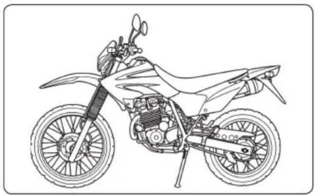
Line drawing of a motorcycle with visible engine, wheels, and structural components (no text or labels)Welcome
The motorcycle presents you a challenge to master the machine, a challenge to adventure. You ride through the wind, linked to the road by a vehicle that responds to your commands as no other does. Unlike an automobile, there is no metal cage around you. Like an airplane, a pre-ride inspection and regular maintenance are essential to your safety. Your reward is freedom.
To meet the challenges safely, and to enjoy the adventure fully, you should become thoroughly familiar with this owner's manual BEFORE YOU RIDE THE MOTORCYCLE.
As you read this manual, you will find information that is preceded by a NOTICE symbol. This information is intended to help you avoid damage to your motorcycle, other property, or the environment.
When service is required, see your Honda dealer that knows your motorcycle best and have skilled technicians trained by the factory and tools to perform high quality services.
Pleasant riding, and thank you for choosing a Honda!
Important Information
■ OPERATOR AND PASSENGER
This motorcycle is designed to carry the operator and one passenger. Never exceed the maximum weight capacity.
■ ON/OFF-ROAD USE
This motorcycle is designed for "dual purpose" use.
■ READ THIS OWNER'S MANUAL CAREFULLY
Pay special attention to the safety messages that appear throughout the manual. These messages are fully explained in the A Few Words About Safety section (page 5).
This manual should be considered a permanent part of the motorcycle and should remain with the motorcycle when resold.
■ The illustrations herein are based on the XR250 Tornado with high seat type.
■ The following codes in this manual indicate each country.
| II LA Latin America (Type II) |
| III LA Latin America (Type III) |
■ The specifications may vary with each locale.
All information in this publication is based on the latest production information available at the time of approval for printing. Moto Honda da Amazônia Ltda. reserves the right to make changes at any time without notice and without incurring any obligation.
No part of this publication may be reproduced without written permission.
A Few Words About Safety
Your safety, and the safety of others, is very important. And operating this motorcycle safely is an important responsibility.
To help you make informed decisions about safety, we have provided operating procedures and other information on labels and in this manual. This information alerts you to potential hazards that could hurt you or others.
Of course, it is not practical or possible to warn you about all hazards associated with operating or maintaining a motorcycle. You must use your own good judgment.
You will find important safety information in a variety of forms, including:
■ Safety Labels — on the motorcycle.
■ Safety Messages — preceded by a safety alert symbol ⚠ and one of two signal words: WARNING or CAUTION.
These signal words mean:

WARNING
You can be killed or seriously hurt if you don't follow instructions.

CAUTION
You can be hurt if you don't follow instructions.
■ Safety Headings — such as Important Safety Reminders or Important Safety Precautions.
■ Safety Section — such as Motorcycle Safety.
■ Instructions — how to use this motorcycle correctly and safely.
This entire manual is filled with important safety information — please read it carefully.
OPERATION
MOTORCYCLE SAFETY 09
Important Safety Information....09
Protective Apparel 10
Load Limits and Guidelines....12
Accessories and Modifications....13
Off-Road Safety 14
PARTS LOCATION 15
Instruments and Indicators.... 18
MAJOR COMPONENTS 29
(Information you need to operate this motorcycle)
Brakes 29
Clutch.... 31
Fuel 33
Engine Oil 36
Tyres....37
ESSENTIAL INDIVIDUAL COMPONENTS 40
Ignition Switch....40
Right Handlebar Controls 41
Left Handlebar Controls....42
FEATURES 43
(Not required for operation)
Steering Lock 43
Helmet Holder 43
Side Cover 44
Document Compartment 45
Headlight Modification 45
OPERATION 46
Pre-ride Inspection 46
Starting the Engine 47
Running-in 48
Riding....49
Shifting 50
Braking....51
Parking 52
Anti-theft Tips....52
(Cont.)
MAINTENANCE 53
The Importance of Maintenance....53
Maintenance Safety 54
Safety Precautions 55
Maintenance Schedule....56
Tool Kit 59
Air Cleaner 60
Crankcase Breather....62
Engine Oil 62
Spark Plug 66
Valve Clearance 67
Throttle Operation....68
Idle Speed 68
Drive Chain 69
Drive Chain Slider....73
Front and Rear Suspension Inspection...... 74
Side Stand 74
Wheels 75
Brake Pad Wear 78
Brake Shoe Wear 79
Battery 79
Fuse Replacement 80
Brake Light Switch Adjustment....82
Bulb Replacement.... 82
Headlight Aim Vertical Adjustment....84
CLEANING 85
STORAGE GUIDE 87
Storage 87
Removal from Storage 88
TAKING CARE OF THE UNEXPECTED 89
MOTORCYCLE IDENTIFICATION 89
Serial Numbers 89
Colour Label....90
SPECIFICATIONS 91
MOTORCYCLE SAFETY
Important Safety Information
Your motorcycle can provide many years of service and pleasure if you take responsibility for your own safety and understand the challenges that you can meet on and off-road.
There is much that you can do to protect yourself when you ride. You'll find many helpful recommendations throughout this manual. Following are a few that we consider most important.
Always Wear a Helmet
It's a proven fact: helmets significantly reduce the number and severity of head injuries. So always wear an approved motorcycle helmet and make sure your passenger does the same. We also recommend that you wear eye protection, sturdy boots, gloves, and other protective gear (page 10).
Make Yourself Easy to See On-Road
Some drivers do not see motorcycles because they are not looking for them.
To make yourself more visible, wear bright reflective clothing, position yourself so other drivers can see you, signal before turning or changing lanes, and use your horn when it will help others notice you.
Be Alert for Off-Road Hazards
The terrain can present a variety of challenges when you ride off-road. Continually “read” the terrain for unexpected turns, drop-offs, rocks, ruts, and other hazards. Always keep your speed low enough to allow time to see and react to hazards.
Ride Within Your Limits
Pushing the limits is another major cause of motorcycle accident both on-road and off.
Never ride beyond your personal abilities or faster than conditions warrant. Remember that alcohol, drugs, fatigue and inattention can significantly reduce your ability to make good judgements and ride safely.
Keep Your Bike in Safe Condition
For safe riding, it's important to keep your motorcycle properly maintained. Having a breakdown can be difficult, especially if you are stranded off-road far from your base. To help avoid problems, inspect your motorcycle before every ride and perform all recommended maintenance. Never exceed load limits, and use only accessories that have been approved by Honda for this motorcycle. See page 12 for more details.
Don't Drink and Ride
Alcohol and riding don't mix. Even one drink can reduce your ability to respond to changing conditions, and your reaction time gets worse with every additional drink. So don't drink and ride, and don't let your friends drink and ride either.
Protective Apparel
For your safety, we strongly recommend that you always wear an approved motorcycle helmet, eye protection, boots, gloves, long pants, and a long-sleeved shirt or jacket whenever you ride. Although complete protection is not possible, wearing proper gear can reduce the chance of injury when you ride. Following are suggestions to help you choose proper gear.

WARNING
■ Not wearing a helmet increases the chance of serious injury or death in a crash.
■ Be sure you and your passenger always wear a helmet, eye protection and other protective apparel when you ride.
Helmets and Eye Protection
Your helmet is your most important piece of riding gear because it offers the best protection against head injuries. A helmet should fit your head comfortably and securely. A bright-coloured helmet can make you more noticeable in traffic, as can reflective strips.
An open-face helmet offers some protection, but a full-face helmet offers more. Always wear a face shield or goggles to protect your eyes and help your vision.
Additional On-Road Gear
In addition to a helmet and eye protection, we also recommend:
■ Sturdy boots with non-slip soles to help protect your feet and ankles.
■ Leather gloves to keep your hands warm and help prevent blisters, cuts, burns and bruises.
■ A motorcycle riding suit or jacket for comfort as well as protection. Bright-coloured and reflective clothing can help make you more noticeable in traffic. Be sure to avoid loose clothes that could get caught on any part of your motorcycle.
Additional Off-Road Gear
On-road apparel may also be suitable for casual off-road riding. But if you plan on any serious off-road riding you will need more serious off-road gear. In addition to your helmet and eye protection, we recommend off-road motorcycle boots and gloves, riding pants with knee and hip pads, a jersey with elbow pads, and a chest/shoulder protector.
Load Limits and Guidelines
Your motorcycle has been designed to carry you and one passenger. When you carry a passenger, you may feel some difference during acceleration and braking. But so long as you keep your motorcycle well-maintained, with good tyres and brakes, you can safely carry loads within the given limits and guidelines.
In addition, exceeding the weight limits or carrying an unbalanced load can seriously affect your motorcycle's handling, braking, and stability. Adding accessories or making modifications that change this motorcycle's design and performance can also make it unsafe. Also, the weight of any accessories will reduce the maximum load the motorcycle can carry. The following pages give more specific information on loading, accessories and modifications.
Loading
How much weight you put on your motorcycle, and how you load it, are important to your safety. If you decide to carry cargo, you should be aware of the following information.

WARNING
■ Overloading or improper loading can cause a crash and you can be seriously hurt or killed.
■ Follow all load limits and other loading guidelines in this manual.
Load Limit
Following is the load limit for your motorcycle:
Maximum weight capacity:
153 kg (337 lbs)
Includes the weight of the operator, passenger, all cargo and all accessories
Loading Guidelines
Your motorcycle is primarily intended for transporting you and a passenger. You may wish to secure a jacket or other small items to the seat when you are not riding with a passenger.
If you wish to carry more cargo, check with your Honda dealer for advice, and be sure to read the information regarding accessories.
Follow these guidelines whenever you carry cargo:
- Keep cargo small and light. Make sure it cannot easily be caught on brush or other objects, and that it does not interfere with your ability to shift position to maintain balance and stability.
■ Place weight as close to the center of the motorcycle as possible. - Do not attach large or heavy items (such as a sleeping bag or tent) to the handlebar, fork, or front fender.
■ Make sure that all cargo is tied down securely before riding.
■ Never exceed the maximum weight limit.
■ Check that both tyres are properly inflated.
Accessories and Modifications
Modifying your motorcycle or using non-Honda accessories can make your motorcycle unsafe. Before you consider making any modifications or adding an accessory, be sure to read the following information.

WARNING
- Improper accessories or modifications can cause a crash in which you can be seriously hurt or killed.
- Follow all instructions in this owner's manual regarding accessories and modifications.
Accessories
We strongly recommend that you use only Honda Genuine Accessories that have been specifically designed and tested for your motorcycle. Because Honda cannot test all other accessories, you must be personally responsible for proper selection, installation and use of non-Honda accessories.
Check with your dealer for assistance and always follow these guidelines:
■ Make sure the accessory does not obscure any lights, reduce ground clearance and banking angle, limit suspension travel or steering travel, alter your riding position or interfere with operating any controls.
- Be sure electrical equipment does not exceed the motorcycle's electrical system capacity (page 95). A blown fuse can cause a loss of lights or engine power.
- Do not pull a trailer or sidecar with your motorcycle. This motorcycle was not designed for these attachments, and their use can seriously impair your motorcycle's handling.
Modifications
We strongly advise you not to remove any original equipment or modify your motorcycle in any way that would change its design or operation. Such changes could seriously impair your motorcycle's handling, stability and braking, making it unsafe to ride.
Removing or modifying your lights, mufflers, emission control system or other equipment can also make your motorcycle illegal.
Off-Road Safety
Learn to ride in an uncongested off-road area free of obstacles before venturing onto unfamiliar terrain.
■ Always obey local off-road riding laws and regulations.
- Obtain permission to ride on private property. Avoid posted areas and obey "NO Trespassing" signs.
- Ride with a friend on another motorcycle so that you can assist each other in case of trouble.
■ Familiarity with your motorcycle is critically important should a problem occur far from help.
■ Never ride beyond your ability and experience or faster than conditions warrant.
■ If you are not familiar with the terrain, ride cautiously. Hidden rocks, holes, or ravines could spell disaster.
- Muffler is required in most off-road areas. Don't modify your exhaust system. Remember that excessive noise bothers everyone and creates a bad image for motorcycling.
PARTS LOCATION
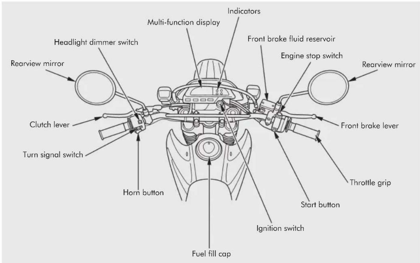
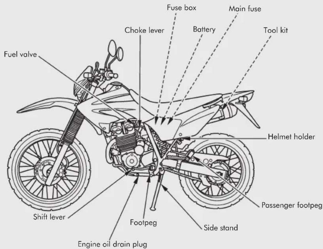
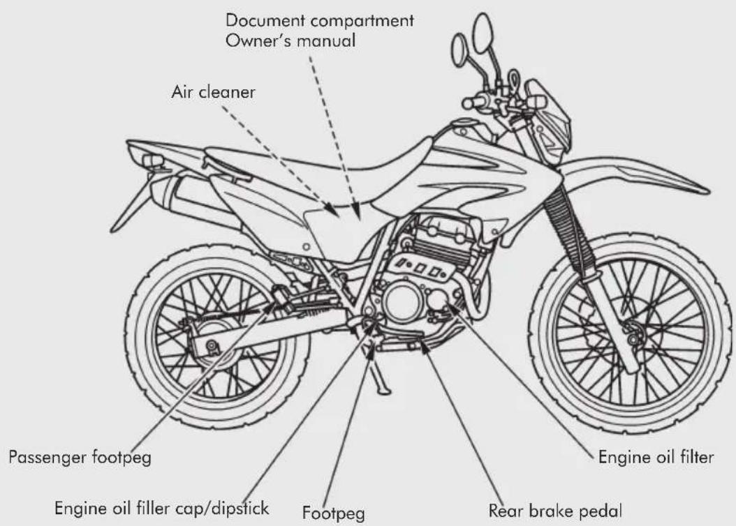
Instruments and Indicators
The indicators are contained in the instrument panel. Their functions are described in the table on the following page.
(1) Multi-function display
(2) High beam indicator
(3) Side stand indicator
(4) Neutral indicator
(5) Turn signal indicator
(6) UP/DOWN button
(7) ADJUST button
(8) RESET-TRIP/TIME button
(9) MODE-TRIP/TIME button
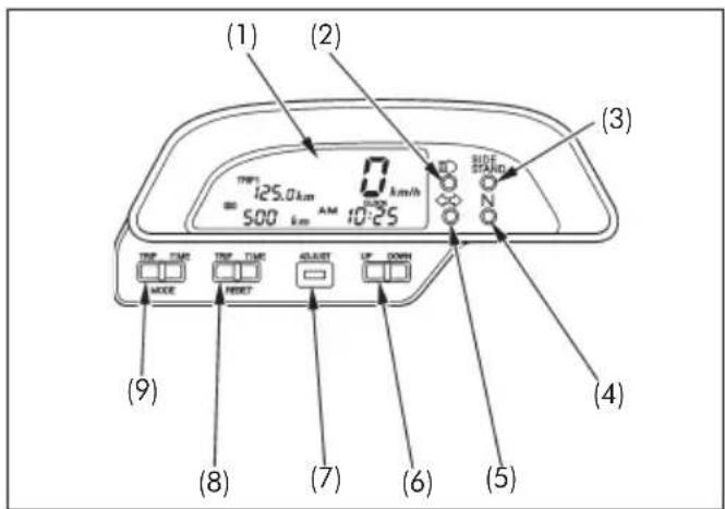
| Ref. | Description Function | |
| (1) | Multi-function display The display | includes the following functions. This display shows the initial display (page 20). |
| Speedometer Shows riding speed | (page 21). | |
| Odometer Shows accumulated mileage | (page 21). | |
| Tripmeter 1 and 2 and “_” Shows mileage per trip (page 21). | ||
| Digital clock Shows hour and minute | (page 25). | |
| Elapsed time meter Shows elapsed time (page 25). | ||
| (2) | High beam indicator (blue) Lights | when the headlight is on high beam. |
| (3) | Side stand indicator (amber) Lights | when the side stand is put down. Before parking, check that the side stand is fully down; the light only indicates the side stand ignition cut-off system (page 74) is activated. |
| (4) | Neutral indicator (green) Lights when the transmission is in neutral. | |
| (5) | Turn signal indicator (amber) Flashes when either turn signal operates. | |
| (6) | UP/DOWN button | These buttons are used to control the multi-function display. |
| (7) | ADJUST button | |
| (8) | RESET-TRIP/TIME button | |
| (9) | MODE-TRIP/TIME button | |
Initial Display
When the ignition switch is turned ON, the display will temporarily show all the modes and digital segments so you can make sure the liquid crystal display is functioning properly.
Both digital clock (1) and tripmeter (2) will reset if the battery is disconnected.
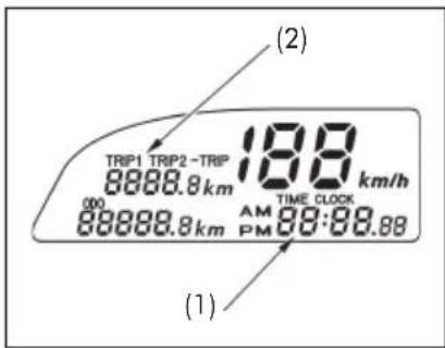
(1) Digital clock/ Elapsed time meter
(2) Tripmeter
Multi-function Display
Multi-function display (1) includes the following functions:
■ Speedometer
■ Odometer
- Tripmeter
■ Digital clock/elapsed time meter
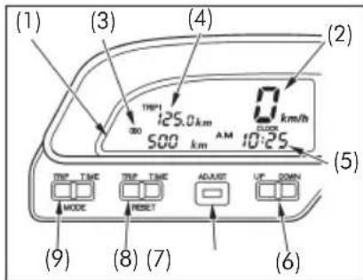
(1) Multi-function display
(2) Speedometer
(3) Odometer
(4) Tripmeter
(5) Digital clock/ Elapsed time meter
(6) UP/DOWN button
(7) ADJUST button
(8) RESET-TRIP/TIME button
(9) MODE-TRIP/TIME button
Speedometer
Shows riding speed.
Odometer
Shows accumulated mileage.
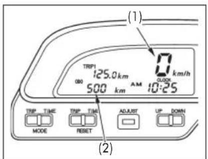
(1) Speedometer
(2) Odometer
Tripmeter
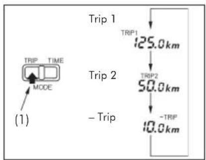
The tripmeter will show mileage in three sub modes, "TRIP 1", "TRIP 2" and"—TRIP".
Each time the MODE-TRIP button (1) is pressed, the indication changes as illustrated.
flowchart
graph TD
    A["TRIP TIME MODE"] --> B["125.0 km"]
    B --> C["TRIP2 50.0 km"]
    C --> D["-TRIP 10.0 km"]
    style A fill:#f9f,stroke:#333
    style B fill:#ccf,stroke:#333
    style C fill:#cfc,stroke:#333
    style D fill:#fcc,stroke:#333
(1) MODE-TRIP button
TRIP 1 and TRIP 2
The tripmeter shows mileage per trip.
(Pressing the ADJUST button allows you to subtract mileage from the instant the button is pressed (page 20).
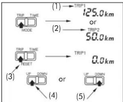
To reset
Press and hold the RESET-TRIP button for more than 1 second. The display will be "0.0 km".
To change mileage reading
The mileage reading can be changed by pressing the UP/DOWN button.
■ The mileage is advanced in increments of a 0.1 km, each time the button is pushed.
■ The mileage is advanced continuously, when the button is pushed and held.
flowchart
graph TD
    A["MODE"] -->|125.0 km or 50.0 km| B["TRIP1"]
    A -->|(2)| C["TRIP2"]
    D["RESET"] -->|(3)| E["UP DOWN"]
    D -->|(4)| F["UP DOWN"]
    G["TRIP TIME"] -->|0.0 km| H["TRIP1"]
(1) TRIP 1
(2) TRIP 2
(3) RESET-TRIP button
(4) UP button
(5) DOWN button
To subtract mileage
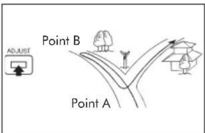
Pressing the ADJUST button starts to subtract mileage from the instant the button is pressed. During subtraction, the mode display will blink.
Example:
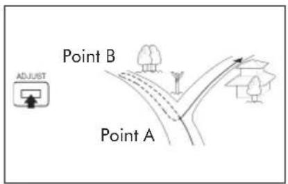
The mileage traveled by mistake as shown in the illustration can be corrected. If the operator chose a wrong route at the point A and realized the mistake at the point B, the tripmeter indication can be corrected by the following.
To start subtraction
Press the ADJUST button at point B, and come back to point A. In this mode, the mileage from point B to point A will be subtracted.
To stop subtraction
Pressing the ADJUST button again upon arrival at point A will switch from subtraction to accumulation.
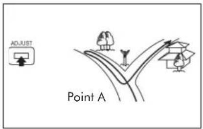
When you go back to the correct route, the mileage traveled on the wrong route is not counted, displaying only the mileage traveled on the correct route.
—TRIP
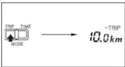
In this mode, the mileage will be subtracted from a preset figure.
Mode selection
Press the MODE-TRIP button and choose the "—TRIP".
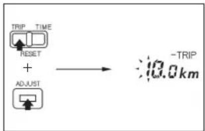
How to set distance
- With the RESET-TRIP button pressed and held, immediately press and hold the ADJUST button for more than a second. The second digit will begin to blink.
(Cont.)
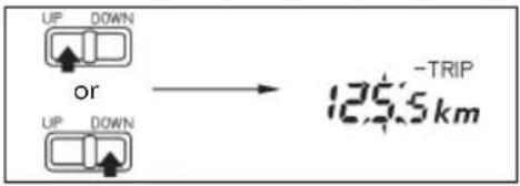
- Press the UP/DOWN button to set the second digit. Pressing and holding the UP/DOWN button will change the meter reading continuously.
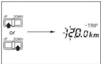
- Press the ADJUST button. The first and the one-tenth digits will begin to blink. Each time the ADJUST button is pressed, the blinking digit will alternate from the second digit to the first and one-tenth digits or vice versa.
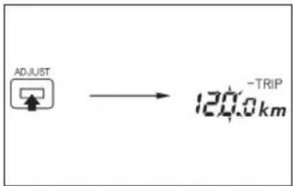
- Press the UP/DOWN button to set the first and the one-tenth digits.
- Press the RESET-TRIP button. The whole mileage will be preset.
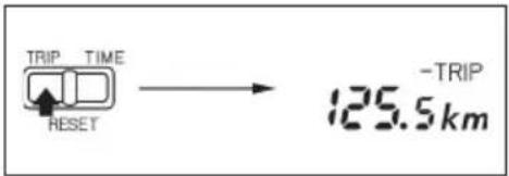
■ Press and hold the RESET-TRIP button for more than 1 second. The preset mileage will be displayed.
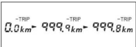
If the actual mileage exceeds the preset figure, "999.9" km will be displayed and continue to decrease.
Digital Clock and Elapsed Time Meter
Each time the MODE-TIME button (1) is pressed, the indication changes as illustrated.
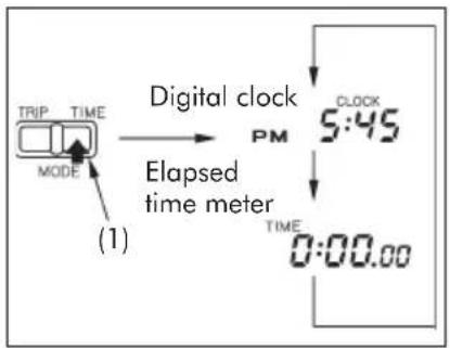
(1) MODE-TIME button
Digital Clock
The digital clock will show hours and minutes up to 12:59 with "AM" and "PM".
To adjust time:
- Press the MODE-TIME button. The mode indicator will display "CLOCK".
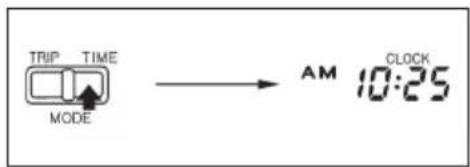
- With the RESET-TIME button pressed and held, immediately press and hold the ADJUST button for more than a second.
"Minutes" in the display will begin to blink.
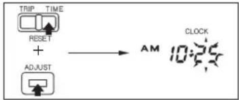
flowchart
graph LR
    A["TRIP TIME RESET"] --> B["+"]
    C["ADJUST"] --> B
    B --> D["AM CLOCK 10:25"]
(Cont.)
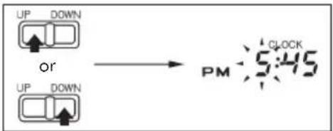
- Press the UP/DOWN button to reset minutes. Pressing and holding the UP/DOWN button will change the meter reading continuously.
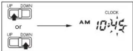
- Press the ADJUST button. Hours in the display will begin to blink. Pressing the ADJUST button will switch the display from hours to minutes, and vice versa.
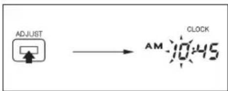
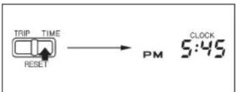
- Press the UP/DOWN button to reset hours and AM/PM.
- Press the RESET-TIME button. The clock will start counting time the instant the button is pressed.
Elapsed Time Meter
The elapsed time meter will show hours, minutes and seconds up to 23:59, 59.
To reset
- Press the MODE-TIME button. The mode indicator will display "TIME".
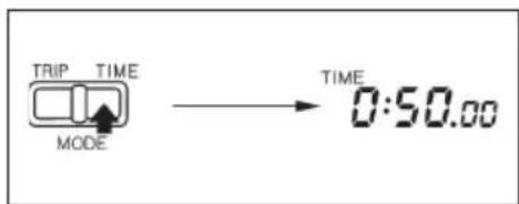
- Press and hold the RESET-TIME button for more than 2 seconds. The display will indicate "0:00".
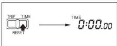
- Lightly press the RESET-TIME button for less than 1 second. The elapsed time meter will start counting time the instant the button is pressed.
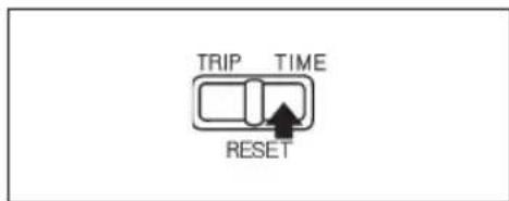
You can start the elapsed time meter before you start off the line in an enduro.
Example:
To start the meter two minutes before the start time.
- Press and hold the RESET-TIME button for more than 2 seconds. The display will indicate "0:00".
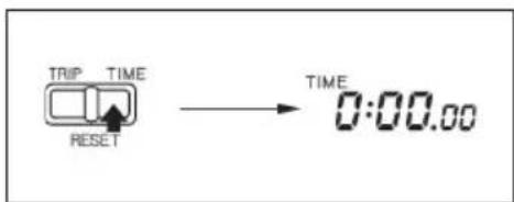
- Set the indication to "23:58:00" with the UP/DOWN button. Pressing and holding the UP/DOWN button will change the meter reading continuously.
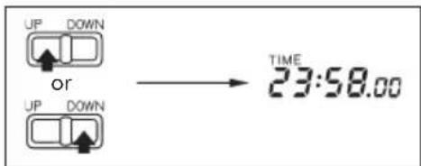
- Two minutes before starting, lightly press the RESET-TIME button for less than 1 second. The elapsed time meter will start to count time the instant the button is pressed.
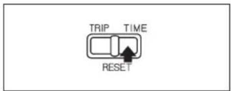
To stop/restart counting
The elapsed time meter will be started or stopped each time the RESET-TIME button is pressed for less than 1 second.
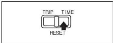
■ Elapsed time meter function will continue even when the multi-function display is switched to "CLOCK" mode or when the ignition switch is turned OFF.
MAJOR COMPONENTS
(Information you need to operate this motorcycle)
Brakes
Front Brake
This motorcycle has a hydraulic front disc brake.
As the brake pads wear, brake fluid level drops. There are no adjustments to perform, but fluid level and pad wear must be inspected periodically. The system must be inspected frequently to ensure there are no fluid leaks. If the brake lever free travel becomes excessive and the brake pads are not worn beyond the recommended limit (page 78), there is probably air in the brake system and it must be bled. See your Honda dealer for this service.
Brake Fluid Level
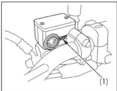
With the motorcycle in an upright position, check the fluid level. It should be above the lower level mark (1). If the level is at or below the lower level mark, check the brake pads for wear (page 78).
Worn pads should be replaced. If the pads are not worn, have your brake system inspected for leaks.
The recommended brake fluid is Honda DOT 4 from a sealed container.
Do not mix different types of brake fluids, because they are not compatible. (E.g.: DOT 4 with DOT 3).
natural_image
Mechanical assembly diagram showing a motor with a gear and shaft, no text or symbols present(1) Lower level mark
Other Checks
Make sure there are no fluid leaks. Check for deterioration or cracks in the hoses and fittings.
Rear Brake
Pedal Height Adjustment
The stopper bolt (1) is provided to allow adjustment of the pedal height.
To adjust the pedal height, loosen the lock nut (2) and turn the stopper bolt. Tighten the lock nut.
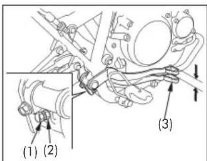
(1) Stopper bolt
(2) Lock nut
(3) Rear brake pedal
Brake Adjustment
- Place the motorcycle on its side stand.
- Measure the distance the rear brake pedal (3) moves before the brake starts to take hold.
Free play should be:
20 - 30 mm (0.8 - 1.2 in)
If adjustment is necessary, turn the rear brake adjusting nut (4).
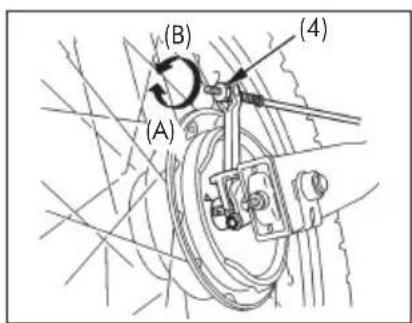
(4) Rear brake adjusting nut
(A) Decrease free play
(B) Increase free play
- Apply the brake several times and check for free wheel rotation after the brake lever is released.
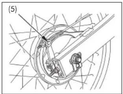
■ Make sure the cutout on the adjusting nut is seated on the brake arm pin (5) after making final free play adjustment.
■ If proper adjustment cannot be obtained by this method, see your Honda dealer.
natural_image
Technical line drawing of a mechanical assembly with no visible text or symbols(5) Brake arm pin
Other Checks
Make sure the brake rod, brake arm, spring and fasteners are in good condition.
Clutch
Clutch adjustment may be required if the motorcycle stalls when shifting into gear or tends to creep; or if the clutch slips, causing acceleration to lag behind engine speed.
Minor adjustments can be made with the clutch cable adjuster (4) at the clutch lever (1).
Normal clutch lever free play is:
10 - 20 mm (0.4 - 0.8 in)
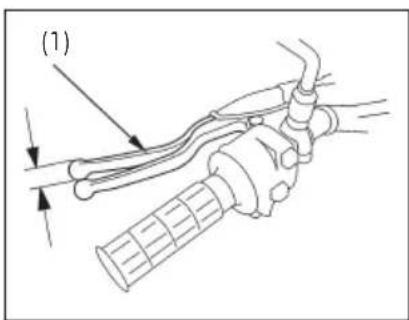
(1) Clutch lever
(Cont.)
- Pull back the rubber dust cover (2).
- Loosen the lock nut (3) and turn the cable adjuster. Tighten the lock nut and check the adjustment.
- If the adjuster is threaded out near its limit or if the correct free play cannot be obtained, loosen the lock nut and turn in the cable adjuster completely. Tighten the lock nut and install the dust cover.
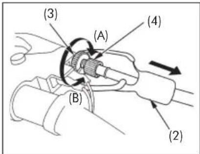
(2) Rubber dust cover
(3) Lock nut
(4) Clutch cable adjuster
(A) Increase free play
(B) Decrease free play
- Loosen the lock nut (5) at the lower end of the cable. Turn the adjusting nut (6) to obtain the specified free play. Tighten the lock nut and check the adjustment.
- Start the engine, pull in the clutch lever and shift into gear. Make sure the engine does not stall and the motorcycle does not creep. Gradually release the clutch lever and open the throttle. The motorcycle should begin to move smoothly and accelerate gradually.
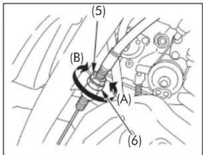
(5) Lock nut
(6) Adjusting nut
(A) Increase free play
(B) Decrease free play
NOTICE
If proper adjustment cannot be obtained or the clutch does not work correctly, see your Honda dealer.
Other Checks
Check the clutch cable for kinks or signs of wear that could cause sticking or failure. Lubricate the clutch cable with a commercially available cable lubricant to prevent premature wear and corrosion.
Fuel
Fuel Valve
The three way fuel valve (1) is on the left side near the carburetor.
OFF
With the fuel valve in the OFF position, fuel cannot flow from the tank to the carburetor. Turn the valve OFF whenever the motorcycle is not in use.
ON
With the fuel valve in the ON position, fuel will flow from the main fuel supply to the carburetor.
RES
With the fuel valve in the RES position, fuel will flow from the reserve fuel supply to the carburetor. Use the reserve fuel only when the main supply is gone. Refill the tank as soon as possible after switching to RES.
The reserve fuel supply is:
3.7 liters (0.98 US gal; 0.81 Imp gal)
NOTICE
Remember to check that the fuel valve is in the ON position each time you refuel. If the valve is left in the RES position, you may run out of fuel with no reserve.
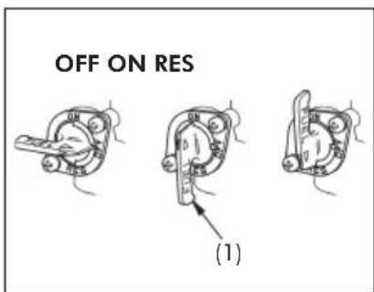
(1) Fuel valve
Fuel Tank
The fuel tank capacity including the reserve supply is: 11.5 liters (3.04 US gal; 2.53 Imp gal)
To open the fuel fill cap (1), insert the ignition key (2) and turn it clockwise. The fuel fill cap will pop up and can be lifted off.
Do not overfill the tank. There should be no fuel in the filler neck (3).
After refueling, to close the fuel fill cap, align the latch in the cap with the slot in the filler neck. Push the fuel fill cap into the filler neck until it snaps closed and locks. Remove the key.
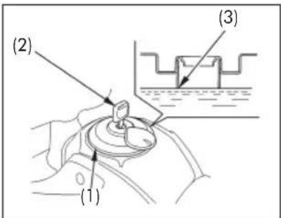
(1) Fuel fill cap
(2) Ignition key
(3) Filler neck

WARNING
Petrol is highly flammable and explosive. You can be burned or seriously injured when handling fuel.
■ Stop the engine and keep heat, sparks, and flame away.
■ Refuel only outdoors.
■ Wipe up spills immediately.
Use unleaded petrol with a research octane number of 91 or higher.
The use of leaded petrol will cause premature damage to the catalytic converter.
NOTICE
If "spark knock" or "pinking" occurs at a steady engine speed under normal load, change brands of petrol. If spark knock or pinking persists, consult your Honda dealer. Failure to do so is considered misuse, and damage caused by misuse is not covered by Honda's Limited Warranty.
Occasionally you may experience light spark knock while operating under heavy loads. This is no cause for concern, it simply means your engine is operating efficiently.
Petrol Containing Alcohol
If you decide to use a petrol containing alcohol (gasohol), be sure it's octane rating is at least as high as that recommended by Honda. There are two types of "gasohol": one containing ethanol, and the other containing methanol. Do not use petrol that contains more than 10% ethanol. Do not use petrol containing methanol (methyl or wood alcohol) that does not also contain cosolvents and corrosion inhibitors for methanol. Never use petrol containing more than 5% methanol, even if it has cosolvents and corrosion inhibitors.
Fuel system damage or engine performance problems resulting from the use of fuels that contain alcohol is not covered under the warranty. Honda cannot endorse the use of fuels containing methanol since evidence of their suitability is as yet incomplete.
Before buying fuel from an unfamiliar station, try to find out if the fuel contains alcohol. If it does, confirm the type and percentage of alcohol used. If you notice any undesirable operating symptoms while using a petrol that contains alcohol, or one that you think contains alcohol, switch to a petrol that you know does not contain alcohol.
Engine Oil
Engine Oil Level Check
Check the engine oil level each day before riding the motorcycle.
The level must be maintained between the upper (1) and lower (2) level marks on the oil filler cap/dipstick (3).
- Start the engine and let it idle for 3 - 5 minutes.
- Stop the engine and hold the motorcycle in an upright position on firm, level ground.
- After 2 – 3 minutes, remove the oil filler cap/dipstick, wipe it clean, and reinsert the dipstick without screwing it in. Remove the dipstick. The oil level should be between the upper and lower level marks.
- If required, add the specified oil (page 62) up to the upper level mark. Do not overfill.
- Reinstall the oil filler cap/dipstick. Check for oil leaks.
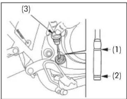
(1) Upper level mark
(2) Lower level mark
(3) Oil filler cap/dipstick
Tyres
To safely operate your motorcycle, the tyres must be the proper type (off-road) and size, in good condition with adequate tread, and correctly inflated.

WARNING
■ Using tyres that are excessively worn or improperly inflated can cause a crash in which you can be seriously hurt or killed.
- Follow all instructions in this owner's manual regarding tyre inflation and maintenance.
Air Pressure
Properly inflated tyres provide the best combination of handling, tread life, and riding comfort. Generally, underinflated tyres wear unevenly, adversely affect handling, and are more likely to fail from being overheated. Underinflated tyres can also cause wheel damage in rocky terrain. Overinflated tyres make your motorcycle ride harshly, are more prone to damage from surface hazards, and wear unevenly.
Make sure the valve stem caps are secure. If necessary, install new caps.
Always check air pressure when your tyres are "cold" – when the motorcycle has been parked for at least three hours. If you check air pressure when your tyres are "warm" – when the motorcycle has been ridden for even a few miles – the readings will be higher than if the tyres were "cold". This is normal, so do not let air out of the tyres to match the recommended cold air pressures given below. If you do, the tyres will be underinflated.
The recommended "cold" tyre pressures are:
| Cold tyre pressures kPa (kgf/cm2, psi) | Front Rear | |
| Operator only | 150(1.50, 22) | 150(1.50, 22) |
| Operator and passenger | 150(1.50, 22) | 200(2.00, 29) |
Inspection
Whenever you check the tyre pressures, you should also examine the tyre treads and sidewalls for wear, damage, and foreign objects.
Look for:
■ Bumps or bulges in the side of the tyre or the tread. Replace the tyre if you find any bumps or bulges.
■ Cuts, splits or cracks in the tyre. Replace the tyre if you can see fabric or cord.
■ Excessive tread wear.
Also, if you hit a pothole or hard object, pull to the side of the road as soon as you can safely and carefully inspect the tyres for damage.
Tread Wear
Replace tyres before tread depth (1) at the center of the tyre reaches the following limit:
| Minimum tread depth | |
| Front 3.0 mm (0.12 in) | |
| Rear 3.0 mm (0.12 in) |
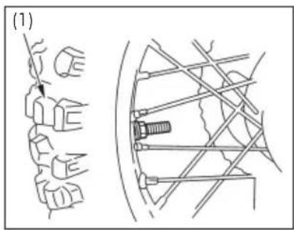
(1) Tread depth
Tube Repair and Replacement
If a tube is punctured or damaged, you should replace it as soon as possible. A tube that is repaired may not have the same reliability as a new one, and it may fail while you are riding.
If you need to make a temporary repair by patching a tube or using an aerosol sealant, ride cautiously at reduced speed and have the tube replaced before you ride again. Any time a tube is replaced, the tyre should be carefully inspected as described on page 38.
Tyre Replacement
The tyres that came on your motorcycle were designed to match the performance capabilities of your motorcycle and provide the best combination of handling, braking, durability and comfort.

WARNING
■ Installing improper tyres on your motorcycle can affect handling and stability. This can cause a crash in which you can be seriously hurt or killed.
- Always use the size and type of tyres recommended in this owner's manual.
The recommended tyres for your motorcycle are:
| Front | 90/90 – 21M/C 54SMETZELER ENDURO 3 |
| Rear | 120/80 – 18M/C 62SMETZELER ENDURO 3 |
| Type Bias | ply, tube |
Whenever you replace a tyre, use one that is equivalent to the original and be sure the wheel is balanced after the new tyre is installed.
Also remember to replace the inner tube whenever you replace a tyre. The old tube will probably be stretched, and if installed in a new tyre, it could fail.
ESSENTIAL INDIVIDUAL COMPONENTS
Ignition Switch
The ignition switch (1) is below the instrument panel.
NOTICE
The headlight and tail light will come on whenever you turn the ignition switch ON. If your motorcycle is stopped with the ignition switch ON and the engine is not running, the headlight and tail light will still be on, resulting in battery discharge.
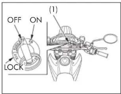
(1) Ignition switch
| Key position Function Key removal | ||
| LOCK(steering lock) | Steering is locked.Engine and lights cannot be operated. | Key can be removed. |
| OFF Engine and lights cannot be operated. Key can be removed. | ||
| ON Engine and lights can be operated. Key cannot be removed. | ||
Right Handlebar Controls
Engine Stop Switch
The engine stop switch (1) is next to the throttle grip. When the switch is in the ○ position, the engine will operate. When the switch is in the ⊗ position, the engine will not operate. This switch is intended primarily as a safety or emergency switch and should normally remain in the ○ position.
NOTICE
If your motorcycle is stopped with the ignition switch ON and the engine stop switch ☑ the headlight and tail light will still be on, resulting in battery discharge.
Start Button
The start button (2) is below the engine stop switch. When the start button is pressed, the starter motor cranks the engine, the headlight will automatically go out, but the tail light will stay on. See page 47 for the starting procedure.
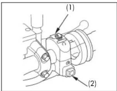
(1) Engine stop switch (2) Start button
Left Handlebar Controls
Headlight Dimmer Switch (1)
Push the dimmer switch to (HI) to select high beam or to (LO) to select low beam.
Turn Signal Switch (2)
Move to ⇔ to signal a left turn, or to ⇒ to signal a right turn. Press to turn signal off.
Horn Button (3)
Press the button to sound the horn.
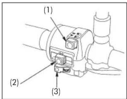
(1) Headlight
dimmer
switch
(2) Turn signal switch
(3) Horn button
FEATURES
(Not required for operation)
Steering Lock
The steering can be locked when the ignition key (1) is in the "LOCK" position.
To lock the steering, turn the handlebar all the way to the left or right, turn the ignition key to LOCK while pushing in. Remove the key.
To unlock the steering, turn the key to OFF.

CAUTION
Do not turn the key to LOCK while riding the motorcycle; loss of vehicle control will result.
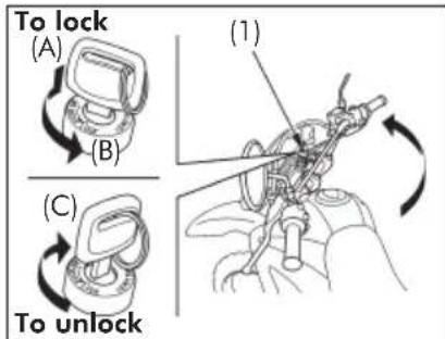
(1) Ignition key
(A) Push in
(B) Turn to LOCK
(C) Turn to OFF
Helmet Holder
The helmet holder (1) is on the left side below the left side cover.
Insert the ignition key (2) into the helmet holder and turn it counterclockwise to unlock.
Hang your helmet on the holder pin (3). Turn the key clockwise to lock the holder and then remove the key.
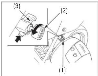
(1) Helmet holder
(2) Ignition key
(3) Holder hook

WARNING
■ Riding with a helmet attached to the holder can interfere with the rear wheel or suspension and could cause a crash in which you can be seriously hurt or killed.
■ Use the helmet holder only while parked. Do not ride with a helmet secured by the holder.
Side Cover
The left side cover must be removed for battery and fuse maintenance.
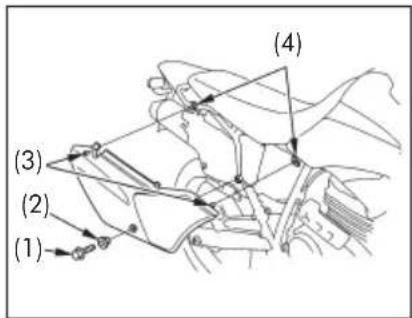
The right side cover must be removed for air cleaner maintenance.
Removal
- Remove the bolt (1) and collar (2).
- Pull out the hooks (3) from the grommets (4).
Installation
Installation can be done in the reverse order of removal.
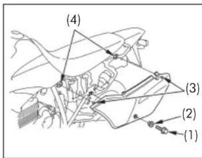
(1) Bolt
(2) Collar
(3) Hooks
(4) Grommets
Document Compartment
The document bag (1) is in the document compartment (2) on the reverse side of the right side cover (3).
The Owner's Manual and other documents should be stored in the document bag.
When washing the motorcycle, be careful not to flood this area with water.
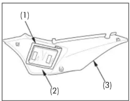
(1) Document bag
(2) Document compartment
(3) Right side cover
Height Modification
(High seat type and Low seat type)
This model is equipped with either the high seat type and low seat type.
By replacing the parts and changing the way the parts are assembled, the low seat type can be modified to the high seat type, and vice versa.
For details of such a modification, contact your Honda dealer.
OPERATION
Pre-ride Inspection
For your safety, it is very important to take a few moments before each ride to walk around your motorcycle and check its condition. If you detect any problem, be sure you take care of it, or have it corrected by your Honda dealer.

WARNING
■ Improperly maintaining this motorcycle or failing to correct a problem before riding can cause a crash in which you can be seriously hurt or killed.
■ Always perform a pre-ride inspection before every ride and correct any problems.
- Engine oil level – add engine oil if required (page 36). Check for leaks.
- Fuel level – fill fuel tank when necessary (page 34). Check for leaks.
- Brakes – check operation;
Front: make sure there is no brake fluid leakage (page 29).
Rear: adjust free play if necessary (page 30).
- Tyres – check condition and pressure (page 37).
- Drive chain – check condition and slack (page 69). Adjust and lubricate if necessary.
- Drive chain slider - check slider wear (page 73).
- Throttle - check for smooth opening and full closing in all steering positions (page 68).
- Clutch – check operation, and adjust if necessary (page 31).
- Lights and horn – check the headlight, brake/tail light, turn signals, indicators and horn for proper operation.
- Spark plug and high tension terminal – check for looseness.
- Engine stop switch - check for proper function (page 41).
- Nuts, bolts, fasteners – check the front wheel to see that the axle nuts are tightened securely. Check security of all other nuts, bolts, and fasteners.
Starting the Engine
Always follow the proper starting procedure described below.

WARNING
Your motorcycle's exhaust contains poisonous carbon monoxide gas. High levels of carbon monoxide can collect rapidly in enclosed areas such as a garage. Do not run the engine with the garage door closed. Even with the door open, run the engine only long enough to move your motorcycle out of the garage.
This motorcycle is equipped with a side stand ignition cut-off system. The engine cannot be started if the side stand is down, unless the transmission is in neutral. If the side stand is up, the engine can be started in neutral or in gear with the clutch lever pulled in. After starting with the side stand down, the engine will shut off if the transmission is put in gear before raising the side stand.
NOTICE
To protect the catalytic converters in your motorcycle's exhaust system, avoid extending idling and the use of leaded petrol.
Do not use the electric starter for more than 5 seconds at a time. Release the start button for approximately 10 seconds before pressing it again.
Preparation
Before starting, insert the key, turn the ignition switch to ON and confirm the following:
■ The transmission is in NEUTRAL (neutral indicator light ON).
■ The engine stop switch is at ☐
■ The fuel valve is ON.
Starting Procedure
Cold Engine
- Pull the choke lever (1) up all the way to Fully ON (A).
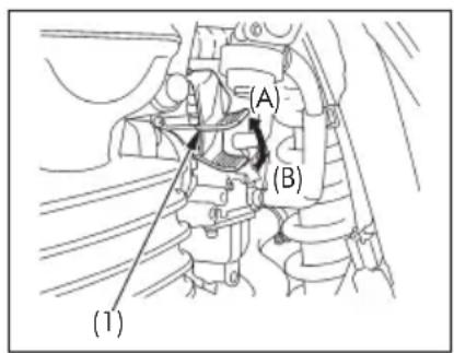
(1) Choke lever
(A) Fully ON
(B) Fully OFF
- With the throttle closed, press the start button.
- When engine speed begins to pick up, operate the choke lever to keep fast idle.
- Continue warming up the engine until it runs smoothly and responds to the throttle, when the choke lever is at Fully OFF (B).
NOTICE
Extended use of the choke may impair piston and cylinder wall lubrication and damage the engine.
Warm Engine
- Do not use the choke.
- Open the throttle slightly.
- Start the engine following step 2 under "Cold Engine."
Flooded Engine
If the engine fails to start after repeated attempts, it may be flooded with excess fuel. To clear a flooded engine, leave the engine stop switch on and push the choke lever down to Fully OFF (B). Open the throttle fully and crank the engine for 5 seconds. If the engine starts, quickly close the throttle, then open it slightly if idling is unstable. If the engine does not start, wait 10 seconds, then follow the Starting Procedure.
Running-in
Help assure your motorcycle's future reliability and performance by paying extra attention to how you ride during the first 500 km (300 miles).
During this period, avoid full-throttle starts and rapid acceleration.
Riding
Review Motorcycle Safety (pages 9 – 14) before you ride.

CAUTION
■ Make sure the side stand is fully retracted before riding the motorcycle. If the stand is extended, it may interfere with control during a left turn.
■ Make sure flammable materials such as dry grass or leaves do not come in contact with the exhaust system when riding, idling, or parking your motorcycle.
- After the engine has been warmed up, the motorcycle is ready for riding.
- While the engine is idling, pull in the clutch lever and depress the shift pedal to shift into 1st (low) gear.
- Slowly release the clutch lever and at the same time gradually increase engine speed by opening the throttle. Coordination of the throttle and clutch lever will assure a smooth positive start.
- When the motorcycle attains a moderate speed, close the throttle, pull in the clutch lever and shift to 2nd gear by raising the shift pedal.
This sequence is repeated to progressively shift to 3rd, 4th, 5th and 6th (top) gears.
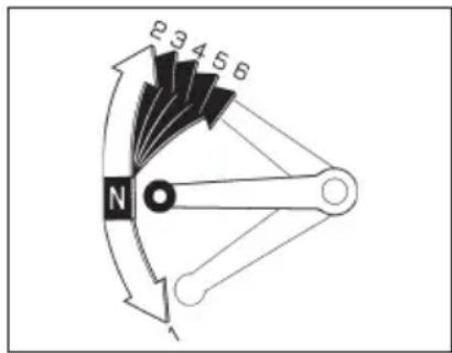
(Cont.)
- Raise the shift lever to shift to a higher gear and depress the shift lever to shift to a lower gear. Each stroke of the shift lever engages the next gear in sequence. The shift lever automatically returns to the horizontal position when released.
■ Do not downshift when traveling at a speed that would force the engine to overrev in the next lower gear; the rear wheel may lose traction, resulting in a possible loss of vehicle control.
■ Do not shift gears without disengaging the clutch and closing the throttle. The engine and drive train could be damaged by overspeed and shock.
- Do not tow the motorcycle or coast for long distances while the engine is off. The transmission will not be properly lubricated and damage may result.
■ Do not run the engine at high rpm with the transmission in neutral or the clutch lever pulled in. Serious engine damage may result.
Shifting
Proper shifting can prevent damaging the engine and transmission.
Upshifting
Upshift to a higher gear before exceeding the upper limit speed.
Upshifting at speeds higher than the upper limit speed can cause damage to the engine.
Downshifting
Downshifting at speeds higher than those in the table below may overrev the engine and can cause damage to the engine and transmission.
Follow the table below when downshifting the gears.
| Downshifting Acceptable Speed | |
| 6th → 5th | 17 km/h (73 mph) or less |
| 5th → 4th | 9 km/h (62 mph) or less |
| 4th → 3rd | 81 km/h (50 mph) or less |
| 3rd → 2nd | 61 km/h (38 mph) or less |
| 2nd → 1st | 39 km/h (24 mph) or less |
Braking
For normal braking, gradually apply both the front and rear brakes while downshifting to suit your road speed. For maximum deceleration, close the throttle and apply the front and rear brakes firmly. Pull in the clutch lever before coming to a complete stop to prevent stalling the engine.
Important Safety Reminders
■ Independent operation of only the brake lever or brake pedal reduces stopping performance.
■ Extreme application of the brake controls may cause wheel lock, reducing control of the motorcycle.
■ When possible, reduce speed or brake before entering a turn; closing the throttle or braking in mid-turn may cause wheel slip. Wheel slip will reduce control of the motorcycle.
■ When riding in wet or rainy conditions, or on loose surfaces, the ability to maneuver and stop will be reduced. All of your actions should be smooth under these conditions. Rapid acceleration, braking or turning may cause loss of control. For your safety, exercise extreme caution when braking, accelerating or turning.
■ When descending a long, steep grade, use engine compression braking by downshifting, with intermittent use of both brakes. Continuous brake application can overheat the brakes and reduce their effectiveness.
■ Riding with your foot resting on the brake pedal or your hand on the brake lever may actuate the brake light, giving a false indication to other drivers. It may also overheat the brakes, reducing effectiveness.
Parking
- After stopping the motorcycle, shift the transmission into neutral, turn the fuel valve OFF, turn the handlebar fully to the left, turn the ignition switch OFF and remove the key.
- Use the side stand to support the motorcycle while parked.
- Lock the steering to help prevent theft (page 43).
NOTICE
■ Park the motorcycle on firm, level ground to prevent it from falling over.
■ If you must park on a slight incline, aim the front of the motorcycle uphill to reduce the possibility of rolling off the side stand or overturning.

CAUTION
■ The exhaust pipe and muffler become very hot during operation and remain sufficiently hot to inflict burns if touched even after shutting off the engine.
■ Make sure flammable materials such as dry grass or leaves do not come in contact with the exhaust system when parking your motorcycle.
Anti-theft Tips
- Always lock the steering and never leave the key in the ignition switch. This sounds simple but people do forget.
- Be sure the registration information for your motorcycle is accurate and current.
- Park your motorcycle in a locked garage whenever possible.
- Use an additional anti-theft device of good quality.
- Put your name, address, and phone number in this Owner's Manual and keep it on your motorcycle at all times. Many times stolen motorcycles are identified by information in the Owner's Manuals that are still with them.
| Name | |
| Address | |
| Phone No. |
MAINTENANCE
The Importance of Maintenance
A well-maintained motorcycle is essential for safe, economical and trouble-free riding. It will also help reduce air pollution.
Because this motorcycle is capable of being ridden over rough off-road terrain as well as on pavement, careful pre-ride inspections and good maintenance are especially important.
To help you properly care for your motorcycle, the following pages include a Maintenance Schedule for regularly scheduled maintenance.
These instructions are based on the assumption that the motorcycle will be used exclusively for its designed purpose. Sustained high speed operation or operation in unusually wet or dusty conditions will require more frequent service than specified in the Maintenance Schedule. Consult your Honda dealer for recommendations applicable to your individual needs and use.
If your motorcycle overturns or becomes involved in a crash, be sure your Honda dealer inspects all major parts, even if you are able to make some repairs.

WARNING
■ Improperly maintaining this motorcycle or failing to correct a problem before you ride can cause a crash in which you can be seriously hurt or killed.
■ Always follow the inspection and maintenance recommendations and schedules in this owner's manual.
Maintenance Safety
This section includes instructions on some important maintenance tasks. You can perform some of these tasks with the tools provided – if you have basic mechanical skills.
Other tasks that are more difficult and require special tools are best performed by professionals. Wheel removal should normally be handled only by a Honda technician or other qualified mechanic; instructions are included in this manual only to assist in emergency service.
Some of the most important safety precautions follow. However, we cannot warn you of every conceivable hazard that can arise in performing maintenance. Only you can decide whether or not you should perform a given task.
! WARNING
■ Failure to properly follow maintenance instructions and precautions can cause you to be seriously hurt or killed.
■ Always follow the procedures and precautions in this owner's manual.
Safety Precautions
■ Make sure the engine is off before you begin any maintenance or repairs. This will help eliminate several potential hazards:
* Carbon monoxide poisoning from engine exhaust.
Be sure there is adequate ventilation whenever you operate the engine.
* Burns from hot parts.
Let the engine and exhaust system cool before touching.
* Injury from moving parts.
Do not run the engine unless instructed to do so.
- Read the instructions before you begin, and make sure you have the tools and skills required.
■ To help prevent the motorcycle from falling over, park it on a firm, level surface, using the side stand or a maintenance stand to provide support.
■ To reduce the possibility of a fire or explosion, be careful when working around petrol or batteries. Use only nonflammable solvent, not petrol, to clean parts. Keep cigarettes, sparks and flames away from the battery and all fuel-related parts.
Remember that your Honda dealer knows your motorcycle best and is fully equipped to maintain and repair it.
To ensure the best quality and reliability, use only new Honda Genuine Parts or their equivalents for repair and replacement.
Maintenance Schedule
Perform the Pre-ride Inspection (page 46) at each scheduled maintenance period.
I: INSPECT AND CLEAN, ADJUST, LUBRICATE OR REPLACE IF NECESSARY
C: CLEAN R: REPLACE A: ADJUST L: LUBRICATE
The following items require some mechanical knowledge. Certain items (particularly those marked * and **) may require more technical information and tools. Consult your Honda dealer.
* Should be serviced by your Honda dealer, unless the owner has proper tools and service data and is mechanically qualified.
** In the interest of safety, we recommend these items be serviced only by your Honda dealer.
Honda recommends that your Honda dealer should road test your motorcycle after each periodic maintenance is carried out.
NOTICE
- At higher odometer readings, repeat at the frequency interval established here.
- Service more frequently when ridden in unusually wet or dusty areas.
- Service more frequently when riding in rain or at full throttle.
- Check the oil level daily before riding the motorcycle and add the recommended oil, if necessary.
- Change every year or at each odometer interval, whichever comes first.
- Service more frequently when riding OFF-ROAD.
- Replace every 2 years or at indicated odometer interval, whichever comes first. Replacement requires mechanical skill.
| Item\Frequency | Whichever comes first → | Odometer Reading (Note 1) | Refer to page | |||||
| ↓ | X 1,000 km 1 | 3 6 | every ...km | |||||
| Note | ||||||||
| * | Fuel line 113,000 — | |||||||
| * | Fuel strainer screen C C C 3,000 — | |||||||
| * | Throttle 1113,000 68 | |||||||
| Choke 1113,000 — | ||||||||
| Air cleaner | Note 2 C | C 3,000 60 | ||||||
| R: every 18,000 km 60 | ||||||||
| Crankcase breather | Note 3 | C C C 3,000 62 | ||||||
| Spark plug | 113,000 66 | |||||||
| R: every 12,000 km 66 | ||||||||
| * | Valve clearance | 1113,000 67 | ||||||
| Engine oil | Notes 4, 5 | R | R | R | 3,000 | 63 | ||
| Engine oil filter | R | R | R | 6,000 | 63 | |||
| * | Carburetor | A A A | 3,000 68 | |||||
| C 6,000 — | ||||||||
| Brake hoses | 1113,000 — | |||||||
| * | Exhaust system | 1113,000 — | ||||||
| * | Secondary air supply system | 1: every 12,000 km | — | |||||
| Engine oil strainer screen | C: every 12,000 km — | |||||||
| Drive chain | Note 6 | 1, L: every 1,000 km | 69 | |||||
| Illumination/Turn signal system | 1113,000 — | |||||||
| Brake fluid | 1113,000 29 | |||||||
| Note 7 R: every 18,000 km | — | |||||||
| Brake pad wear 113,000 78 | ||||||||
| Brake shoes wear 113,000 79 | ||||||||
| Brake system 1113,000 29, 78, 79 | ||||||||
| * | Brake light switch 1113,000 82 | |||||||
| * | Headlight aim A A 3,000 84 | |||||||
| Clutch system 1113,000 31 | ||||||||
| Side stand | 113,000 74 | |||||||
| * | Front and rear suspensions | 16,000 74 | ||||||
| * | Nuts, bolts, fasteners | Note 6 | 1 | 1 | 1 | 3,000 | — | |
| ** | Rims and wheels | Note 6 | 1113,000 | — | ||||
| Tyres | A: every 1,000 km | 37 | ||||||
| ** | Steering head bearings | 113,000 | — | |||||
| Instruments/Switches | 1113,000 | — | ||||||
| Front suspension oil | R: every 12,000 km — | |||||||
| Drive chain slider 1113,000 | — | |||||||
Tool Kit
The tool kit (1) is in the tool box (2) behind the left side cover.
To open the tool box lid (3) insert the ignition key (4) into the tool box lid. Turn it counterclockwise, then open the tool box lid.
Some roadside repairs, minor adjustments and parts replacement can be performed with the tools contained in the kit.
■ 10 x 12 mm Open end wrench
■ 14 x 17 mm Open end wrench
■ No. 1 Screwdriver
■ No. 3 Phillips
■ 24 mm Box end wrench
■ Extension bar
■ Spark plug wrench
■ 8 mm Box wrench
■ Tool bag
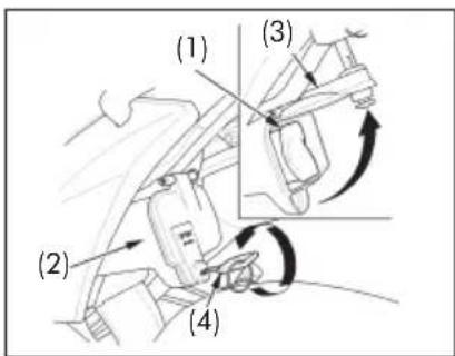
(1) Tool kit
(2) Tool box
(3) Tool box lid
(4) Ignition key
Air Cleaner
(Refer to the Safety Precautions on page 55.)
The air cleaner should be serviced at regular intervals (page 56). Service more frequently when riding in unusually wet or dusty areas.
- Remove the right side cover (page 44).
- Remove the air cleaner housing cover (1) by removing the screws (2).
- Unhook the retainers (3) from the air cleaner housing, then remove the air cleaner case (4).
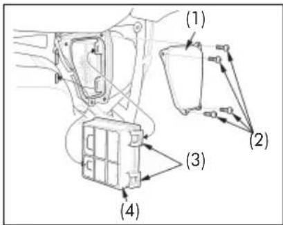
(1) Air cleaner housing cover
(2) Screws
(3) Retainers
(4) Air cleaner case
- Take out the air cleaner A (5) and air cleaner B (6).
- Clean each air cleaner by tapping it lightly to loosen the dust. Blow away the remaining dust by applying compressed air from the side of the carburator, or replace if necessary.
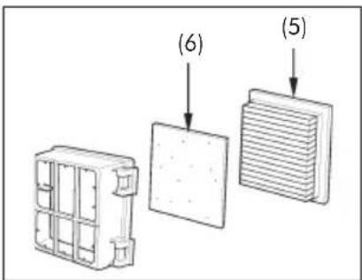
(5) Air cleaner A
(6) Air cleaner B
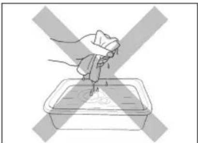
Do not soak the air cleaners in oil.
natural_image
Illustration of a hand holding a cloth above a container with liquid, crossed by a diagonal X (no text or symbols)- Install the air cleaner B (6) to the air cleaner case (4).
- Install the air cleaner A (5). Be sure to align the lugs (7) to the air cleaner as shown.
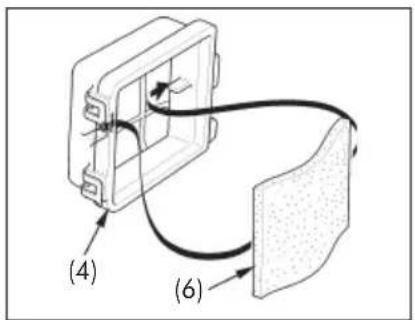
(4) Air cleaner case
(6) Air cleaner B
- Install the air cleaner case by aligning its tabs (8) with the housing slits (9) and hook the retainers.
- Install the removed parts in the reverse order of removal.
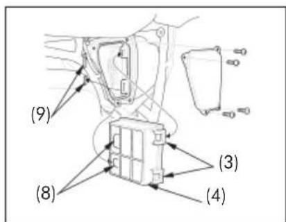
(3) Retainers
(4) Air cleaner case
(8) Tabs
(9) Slits
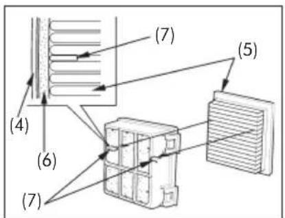
(5) Air cleaner A
(7) Lugs
Crankcase Breather
(Refer to the Safety Precautions on page 55.)
-
Remove the crankcase breather tube plug (1) and drain deposits into a suitable container.
-
Reinstall the crankcase breather tube plug.
Service more frequently when riding in rain, at full throttle, or when the deposits can be seen in the transparent section of the crankcase breather tube.
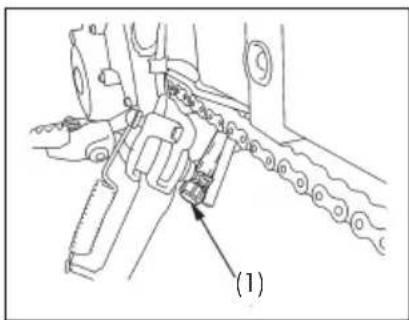
(1) Crankcase breather tube plug
Engine Oil
(Refer to the Safety Precautions on page 55.)
Oil Recommendation
| API classification SG | or higher except oils labeled as energy conserving on the circular API service label |
| Viscosity (weight) 10W-30 | |
| JASO T 903 standard | MA |
| Suggested oil Oil which | Honda recommends |
■ Your motorcycle does not need oil additives. Use the recommended oil.
■ Do not use oils with graphite or molybdenum additives. They may adversely affect clutch operation.
- Do not use API SH or higher oils displaying a circular API "energy conserving" service label on the container. They may affect lubrication and clutch performance.
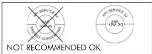
■ Do not use non-detergent, vegetable, or castor based racing oil.
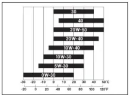
Other viscosities shown in the following chart may be used when the outside air temperature in your riding area is within the indicated range.
bar
| Temperature Range | Value | | :--- | :--- | | 30 | 40 | | 40 | 40 | | 20W-50 | 50 | | 20W-40 | 45 | | 10W-40 | 35 | | 10W-30 | 25 | | 5W-30 | -15 | | 0W-30 | -30 |Outside Air Temperature
JASO T 903 Standard
The JASO T 903 standard is an index to choose engine oils for 4-stroke motorcycle engines.
There are two classes: MA and MB.
Oil conforming to the standard has the following classification on the oil container.
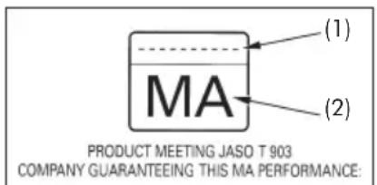
(1) Code number of the sales company of the oil
(2) Oil classification
Engine Oil and Filter
Engine oil quality is the chief factor affecting engine service life. Change the engine oil as specified in the maintenance schedule (page 56).
When running in very dusty conditions, oil changes should be performed more frequently than specified in the maintenance schedule.
Please dispose of used engine oil in a manner that is compatible with the environment. We suggest you take it in a sealed container to your local recycling center or service station for reclamation. Do not throw it in the trash or pour it on the ground or down a drain.

CAUTION
Used engine oil may cause skin cancer if repeatedly left in contact with the skin for prolonged periods. Although this is unlikely unless you handle used oil on a daily basis, it is still advisable to thoroughly wash your hands with soap and water as soon as possible after handling used oil.
(Cont.)
Changing the oil requires a torque wrench. If you do not have it and the necessary skill, we recommend that you have your Honda dealer perform this service.
NOTICE
If a torque wrench is not used for this installation, see your Honda dealer as soon as possible to verify proper assembly.
Change the engine oil with the engine at normal operating temperature and the motorcycle on its side stand to assure complete and rapid draining.
- To drain the oil, remove the oil filler cap/dipstick, oil drain plug (1) and sealing washer (2).
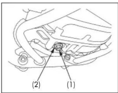
(1) Oil drain plug (2) Sealing washer
-
After the engine oil has been drained out, hold the motorcycle upright for 10 – 15 seconds to assure complete draining.
-
Remove the oil filter cover bolts (3), oil filter cover (4) and oil filter (5).
-
Check that the oil filter cover O-ring (6) is in good condition and then install the new oil filter. Use the Honda oil filter or an equivalent filter specified for your model. Other filters not specified for your model may not filter impurities properly.
-
Install the oil filter with the rubber seal (7) facing out, away from the engine. You will see OUT-SIDE mark (8) on the filter body, near the seal.
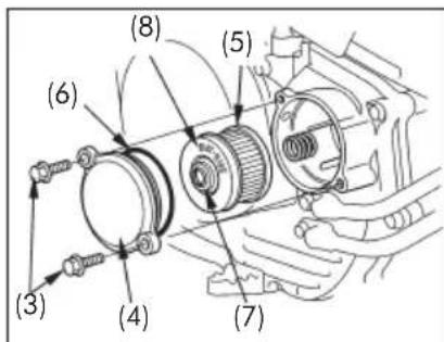
(3) Oil filter cover bolts (4) Oil filter cover (5) Oil filter (6) O-ring (7) Rubber seal (8) OUT-SIDE mark
NOTICE
Improper installation of the oil filter can cause serious engine damage.
- Reinstall the oil filter cover, making sure the bolts are tightened securely.
Oil filter cover bolts torque:
12 N.m (1.2 kgf.m; 9 lbf.ft)
- Check that the sealing washer on the drain plug is in good condition and install the plug. Replace the sealing washer every other time the oil is changed, or each time if necessary.
Oil drain plug torque:
30 N.m (3.0 kgf.m; 22 lbf.ft)
- Fill the crankcase with the recommended grade oil; approximately:
1.5 liter (1.6 US qt; 1.3 Imp qt)
-
Install the oil filler cap/dipstick.
-
Start the engine and let it idle for 3 - 5 minutes.
-
2 – 3 minutes after stopping the engine, check that the oil level is at the upper level mark on the dipstick with the motorcycle upright on firm, level ground. Make sure there are no oil leaks.
Spark Plug
(Refer to the Safety Precautions on page 55.)
Recommended plugs:
Standard: CR8EH - 9S (NGK)
For extended high speed riding:
CR9EH - 9S (NGK)
NOTICE
Never use a spark plug with an improper heat range. Severe engine damage could result
- Disconnect the spark plug cap (1) from the spark plug.
- Clean any dirt from around the spark plug base. Remove the spark plug using the spark plug wrench furnished in the tool kit.
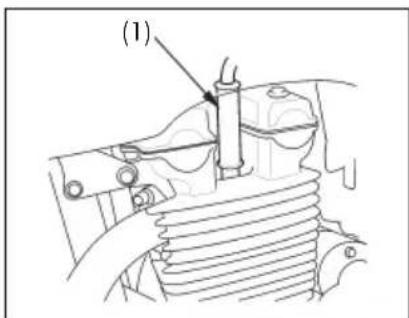
(1) Spark plug cap
-
Visually inspect the spark plug electrodes for wear. The center electrode should have square edges and the side electrode should not be eroded. Discard the spark plug if there is apparent wear or if the insulator is cracked or chipped.
-
Check the spark plug gap (2) using a wire-type feeler gauge. If adjustment is necessary, bend the side electrode (3) carefully.
The gap should be: 0.80 - 0.90 mm (0.031 - 0.035 in)
- Make sure the plug washer is in good condition.
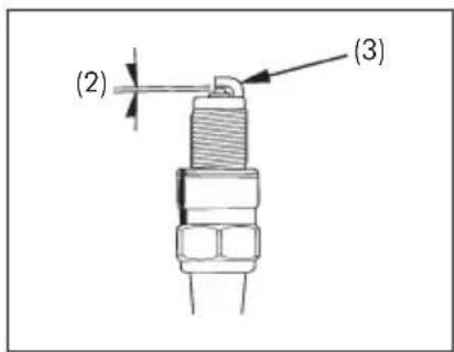
(2) Spark plug gap
(3) Side electrode
-
With the plug washer attached, thread the spark plug in by hand to prevent cross-threading.
-
Tighten the spark plug:
■ If the old plug is good:
1/8 turn after it seats.
■ If installing a new plug, tighten it twice to prevent loosening:
a) First, tighten the plug:
NGK: 3/4 turn after it seats.
b) Then loosen the plug.
c) Next, tighten the plug again:
1/8 turn after it seats.
NOTICE
Improperly tightened spark plug can damage the engine. If a plug is too loose, a piston may be damaged. If a plug is too tight, the threads may be damaged.
- Reinstall the spark plug cap. Take care to avoid pinching any cables or wires.
Valve Clearance
(Refer to the Safety Precautions on page 55.)
Valve clearance should be inspected and adjusted according to the intervals specified in the Maintenance Schedule (page 56).
See an authorized Honda dealer to have the valves inspected and adjusted.
NOTICE
■ It is necessary to use a measuring device to perform this service.
■ Excessive valve clearance will cause engine noise. Little or no clearance may damage the valves or cause power loss.
Throttle Operation
(Refer to the Safety Precautions on page 55.)
-
Check for smooth rotation of the throttle grip from the fully open to the fully closed position at both full steering positions.
-
Measure the throttle grip free play at the throttle grip flange.
The standard free play should be approximately:
$$ 2. 0 - 6. 0 \mathrm{mm} (0. 0 8 - 0. 2 4 \text { in }) $$
To adjust the free play, loosen the lock nut (1) and turn the adjuster (2).
After adjustment, tighten the lock nut.
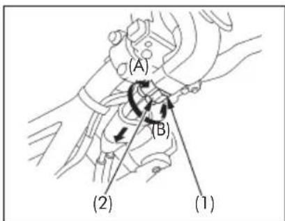
(1) Lock nut
(2) Adjuster
(A) Increase free play
(B) Decrease free play
Idle Speed
(Refer to the Safety Precautions on page 55.)
The engine must be at normal operating temperature for accurate idle speed adjustment. Ten minutes of stop-and-go riding is sufficient.
Do not attempt to compensate for faults in other systems by adjusting idle speed. See your Honda dealer for regularly scheduled carburetor adjustments.
- Warm up the engine and hold the motorcycle upright. Shift to neutral.
- Connect a tachometer to the engine.
- Adjust idle speed with the throttle stop screw (1). Idle speed (In neutral):
$$ 1, 4 0 0 \pm 1 0 0 \min ^ {- 1} (\mathrm{rpm}) $$
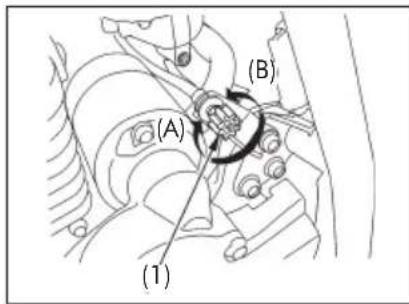
(1) Throttle stop screw
(A) Increase rpm
(B) Decrease rpm
Drive Chain
(Refer to the Safety Precautions on page 55.)
The service life of the drive chain (1) is dependent upon proper lubrication and adjustment. Poor maintenance can cause premature wear or damage to the drive chain and sprockets.
The drive chain should be checked, adjusted and lubricated as part of the Pre-ride Inspection (page 46). Under severe usage, or when the motorcycle is ridden in unusually dusty or muddy areas, more frequent maintenance will be necessary.
Inspection
- Turn the engine off, raise the rear wheel off the ground by placing a support under the engine, and shift the transmission into neutral.
- Check slack in the lower drive chain run midway between the sprockets.
Drive chain slack should be adjusted to allow the following vertical movement by hand:
20 - 30 mm (0.8 - 1.2 in)
- Roll the motorcycle forward. Stop. Check the drive chain slack. Repeat this procedure several times. Drive chain slack should remain constant. If the chain is slack only in certain sections, some links are kinked and binding. Binding and kinking can frequently be eliminated by lubrication.
NOTICE
Excessive chain slack may allow the drive chain to damage the engine cases.
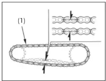
(1) Drive chain
(Cont.)
- Roll the motorcycle forward. Stop and place it on its side stand. Inspect the drive chain and sprockets for any of the following conditions:
DRIVE CHAIN
* Damaged Rollers
* Loose Pins
* Dry or Rusted Links
* Kinked or Binding Links
* Excessive Wear
* Improper Adjustment
* Damaged or Missing O-rings
SPROCKETS
* Excessively Worn Teeth
* Broken or Damaged Teeth
A drive chain with damaged rollers, loose pins, or missing O-rings must be replaced. A chain which appears dry, or shows signs of rust, requires supplementary lubrication. Kinked or binding links should be thoroughly lubricated and worked free. If links cannot be freed, the chain must be replaced.
Damaged sprocket teeth
Replace

Worn sprocket teeth
Replace
Normal sprocket teeth
GOOD
Adjustment
Drive chain slack should be checked and adjusted, if necessary, every 1,000 km (600 miles). When operated at sustained high speeds or under conditions of frequent rapid acceleration, the chain may require more frequent adjustment.
If the drive chain requires adjustment, the procedure is as follows:
- Place the motorcycle on its side stand with the transmission in neutral and the ignition switch off.
- Loosen the rear axle nut (1).
- Loosen the lock nuts (2) on both drive chain adjusting nuts (3).
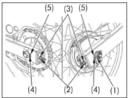
(1) Rear axle nut
(2) Lock nuts
(3) Drive chain adjusting nuts
(4) Index marks
(5) Rear edge of adjusting slots
- Turn both drive chain adjusting nuts an equal number of turns until the correct drive chain slack is obtained. Turn the drive chain adjusting nuts clockwise to tighten the chain, or counterclockwise to provide more slack. Adjust the chain slack at a point midway between the drive sprocket and the rear wheel sprocket. Rotate the rear wheel and recheck slack at other sections of the chain.
Chain slack should be:
$$ 2 0 - 3 0 \mathrm{mm} (0. 8 - 1. 2 \text { in }) $$
- Check rear axle alignment by confirming the chain adjuster index marks (4) against the rear edge (5) of the adjusting slots.
Both marks should correspond. If the axle is misaligned, turn the right or left adjusting nut until the marks correspond on the rear edge of the adjusting slots and recheck chain slack.
- Tighten the rear axle nut to specified torque. Rear axle nut torque:
88 N.m (9.0 kgf.m; 65 lbf.ft)
NOTICE
If a torque wrench is not used for this installation, see your Honda dealer as soon as possible to verify proper assembly.
- Tighten the drive chain adjusting nuts lightly, then tighten the lock nuts by holding the adjusting nuts with a spanner.
- Recheck drive chain slack.
- Rear brake pedal free play is affected when repositioning the rear wheel to adjust drive chain slack. Check rear brake pedal free play and adjust as necessary (page 30).
Wear inspection
Check the chain wear label when adjusting the chain. If the red zone (6) on the label aligns with the arrow mark (7) on the chain adjuster plates after the chain has been adjusted to the proper slack, the chain is excessively worn and must be replaced. The proper slack is:
20 - 30 mm (0.8 - 1.2 in)
Damage to the bottom part of the frame may be caused by excessive drive chain slack of more than:
60 mm (2.4 in)
Replacement chain: D.I.D. 520 VD
This motorcycle has a staked master link drive chain which requires a special tool for cutting and staking. Do not use an ordinary master link with this chain. See your Honda dealer.
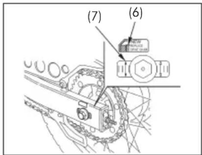
(6) Red zone
(7) Arrow mark
Lubrication and Cleaning
Lubricate every 1,000 km (600 miles) or sooner if chain appears dry.
The drive chain on this motorcycle is equipped with small O-rings between the link plates. These O-rings retain grease inside the chain to improve its service life.
The O-rings in this chain can be damaged by steam cleaning, high pressure washers, and certain solvents. Clean the side surfaces of the chain with a dry cloth. Do not brush the rubber O-rings. Brushing will damage them. Wipe dry and lubricate only with SAE 80 or 90 gear oil. Commercial chain lubricants may contain solvents which could damage the rubber O-rings.
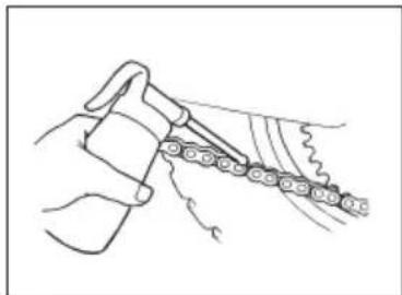
natural_image
Line drawing of a hand holding a chain with chains extending outward (no text or symbols)Drive Chain Slider
(Refer to the Safety Precautions on page 55.)
Check the drive chain slider (1) for wear.
The chain slider must be replaced if it is worn to the bottom of wear limit cutout (2).
For replacement, see your Honda dealer.
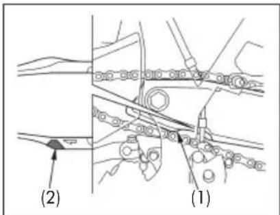
(1) Drive chain slider
(2) Wear limit cutout
Front and Rear Suspension Inspection
(Refer to the Safety Precautions on page 55.)
- Check the fork assembly by locking the front brake and pumping the fork up and down vigorously. Suspension action should be smooth and there must be no oil leakage.
- Swingarm bearings should be checked by pushing hard against the side of the rear wheel while the motorcycle is on a support block. Free play indicates worn bearings.
- Carefully inspect all front and rear suspension fasteners for tightness.
Side Stand
(Refer to the Safety Precautions on page 55.)
Perform the following maintenance in accordance with the maintenance schedule.
Functional Check
-
Check the side stand spring (1) for damage or loss of tension and the side stand assembly for freedom of movement.
■ Check the side stand ignition cut-off system: -
Sit astride the motorcycle; put the side stand up and the transmission in neutral.
-
Start the engine and with the clutch lever pulled in, shift the transmission into gear.
-
Lower the side stand. The engine should stop as you put the side stand down.
If the side stand system does not operate as described, see your Honda dealer for service.
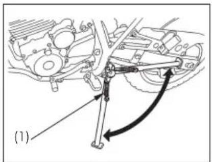
(1) Side stand spring
Wheels
(Refer to the Safety Precautions on page 55.)
Front Wheel Removal
- Raise the front wheel off the ground by placing a support block under the engine.
- Remove the speedometer cable set screw (1) and disconnect the speedometer cable (2).
- Loosen the axle holder nuts (3).
- Unscrew the front axle shaft (4). Remove the wheel.
Do not depress the brake lever when the wheel is off the motorcycle. The caliper piston will be forced out of the cylinder with subsequent loss of brake fluid. If this occurs, servicing of the brake system will be necessary. See your Honda dealer for this service.
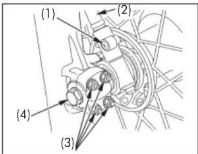
(1) Speedometer cable set screw
(2) Speedometer cable
(3) Axle holder nuts
(4) Front axle shaft
Installation Notes
■ Reverse the removal procedure.
■ Insert the front axle shaft through the wheel hub and left fork leg. Make sure that the tang (5) on the speedometer gearbox is located behind the tang (6) on the right fork leg.
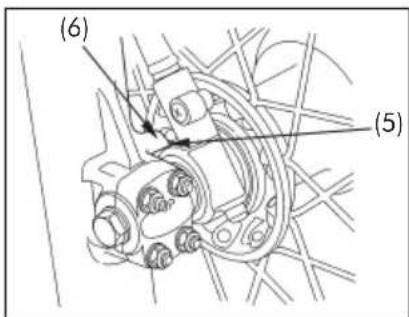
(5) Tang (Speedometer gear box)
(6) Tang
(Right fork leg)
■ Tighten the front axle shaft to the specified torque. Front axle shaft torque:
59 N.m (6.0 kgf.m; 44 lbf.ft)
■ Tighten the upper axle holder nuts to the specified torque first, then tighten the lower axle holder nuts to same torque.
Axle holder nut torque:
12 N.m (1.2 kgf.m; 9 lbf.ft)
■ After installing the wheel, apply the brake several times and then check if the wheel rotates freely. Recheck the wheel if the brake drags or if the wheel does not rotate freely.

CAUTION
If a torque wrench was not used for installation, see your Honda dealer as soon as possible to verify proper assembly. Improper assembly may lead to loss of braking capacity.
Rear Wheel Removal
- Raise the rear wheel off the ground by placing a support block under the engine.
- Remove the rear brake adjusting nut (1), disconnect the brake rod (2) from the brake arm (3) by pushing down on the rear brake pedal.
- Loosen the drive chain lock nuts (4) and drive chain adjusting nuts (5).
- Remove the rear axle nut (6), while holding the rear axle at the other end with a wrench.
- Pull out the rear axle shaft (7).
- Remove the drive chain from the driven sprocket by pushing the rear wheel forward.
- Remove the rear wheel.
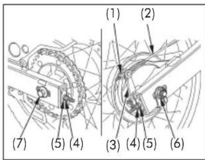
(1) Rear brake adjusting nut
(2) Brake rod
(3) Brake arm
(4) Drive chain lock nuts
(5) Drive chain adjusting nuts
(6) Rear axle nut
(7) Rear axle shaft
Installation Notes
■ Reverse the removal procedure.
■ Make sure that the lug (9) on the swingarm (10) is located in the slot (8) in the brake panel.
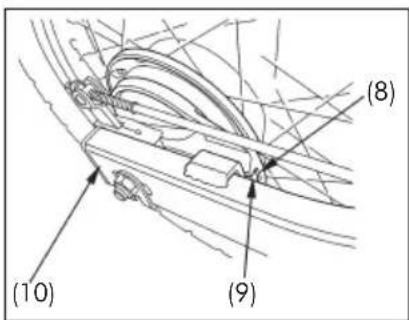
(8) Slot
(9) Lug
(10) Swingarm
■ Tighten the rear axle nut to specified torque:
Rear axle nut torque:
88 N.m (9.0 kgf.m; 65 lbf.ft)
■ Adjust the drive chain (page 71) and rear brake pedal free play (page 30).
■ Apply the brake several times and check for free wheel rotation after the brake pedal is released.

CAUTION
If a torque wrench was not used for installation, see your Honda dealer as soon as possible to verify proper assembly. Improper assembly may lead to loss of braking capacity.
Brake Pad Wear
(Refer to the Safety Precautions on page 55.)
Brake pad wear depends upon the severity of usage, the type of riding, and road conditions. (Generally, the pads will wear faster on wet and dirty roads.) Inspect the pads at each regular maintenance interval (page 56).
Front Brake
Check the cutout (1) in each pad. If either pad is worn to the cutout, replace both pads as a set. See your Honda dealer for this service.
Front brake
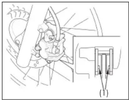
natural_image
Mechanical assembly diagram showing a component with arrows indicating direction (no text or symbols present)(1) Cutouts
Brake Shoe Wear
(Refer to the Safety Precautions on page 55.)
The rear brake is equipped with brake wear indicator. When the brake is applied, an arrow (1) attached to the brake arm (2) moves toward a reference mark (3) on the brake panel (4). If the arrow aligns with the reference mark on full application of the brake, the brake shoes must be replaced. See your Honda dealer for this service.
When the brake service is necessary, see your Honda dealer. Use only genuine Honda parts or its equivalent.
Rear brake
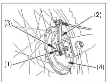
(1) Arrow
(2) Brake arm
(3) Reference mark
(4) Brake panel
Battery
(Refer to the Safety Precautions on page 55.)
It is not necessary to check the battery electrolyte level or add distilled water as the battery is a maintenance-free (sealed) type. If your battery seems weak and/or is leaking electrolyte (causing hard starting or other electrical troubles), contact your Honda dealer.
NOTICE
Your battery is a maintenance-free type and can be permanently damaged if the cap strip is removed.

WARNING
■ The battery gives off explosive hydrogen gas during normal operation.
■ A spark or flame can cause the battery to explode with enough force to kill or seriously hurt you.
■ Wear protective clothing and a face shield, or have a skilled mechanic do the battery maintenance.
(Cont.)
Removal
- Make sure the ignition switch is OFF.
- Remove the left side cover (page 44).
- Remove the bolt (1) and battery holder (2).
- Disconnect the negative (−) terminal lead (3) from the battery first, then disconnect the positive (+) terminal lead (4).
- Pull out the battery (5) from the battery box.
Installation
- Reinstall in the reverse order of removal. Be sure to connect the positive (+) terminal first, then the negative (−) terminal.
- Check all bolts and other fasteners are secure.
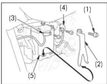
(1) Bolt
(2) Battery holder
(3) Negative (−) terminal lead
(4) Positive (+)
terminal lead
(5) Battery
Fuse Replacement
(Refer to the Safety Precautions on page 55.)
When frequent fuse failure occurs, it usually indicates a short circuit or an overload in the electrical system. See your Honda dealer for repair.
NOTICE
Never use a fuse with a different rating from that specified. Serious damage to the electrical system or a fire may result, causing a dangerous loss of lights or engine power.
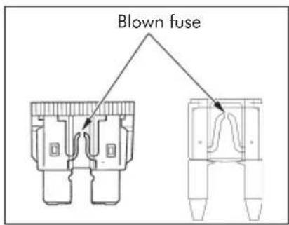
Fuse Box
The fuse box (1) is located behind the left side cover. The specified fuses are: 10 A and 15 A.
- Remove the left side cover (page 44).
- Open the fuse box cover (2).
- Pull out the fuse old fuse and install a new fuse. The spare fuses (3) are located in the fuse box.
- Close the fuse box cover and install the left side cover.
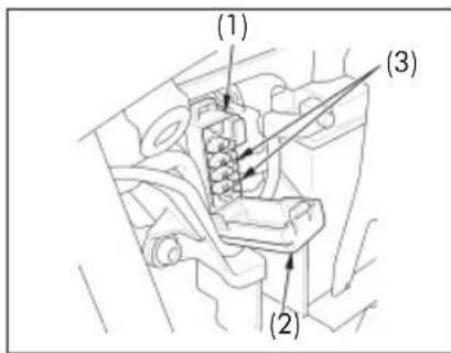
(1) Fuse box
(2) Fuse box cover
(3) Spare fuses
Main Fuse
The main fuse (1) is located behind the left side cover. The specified fuse is: 20 A
- Remove the left side cover (page 44).
- Disconnect the wire connector (2) of the starter magnetic switch (3).
-
Pull out the old fuse. If the main fuse is blown, install a new fuse.
The spare main fuse (4) is located under the starter magnetic switch. -
Reconnect the wire connector and install the left side cover.
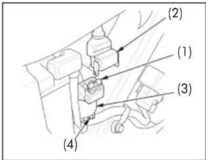
(1) Main fuse
(2) Wire connector
(3) Starter magnetic switch
(4) Spare main fuse
Brake Light Switch Adjustment
(Refer to the Safety Precautions on page 55.)
Check the operation of the brake light switch (1) at the right side behind the engine from time to time. Adjustment is done by turning the adjusting nut (2). Turn the nut in the direction (A) if the switch operates too late and in direction (B) if the switch operates too soon.
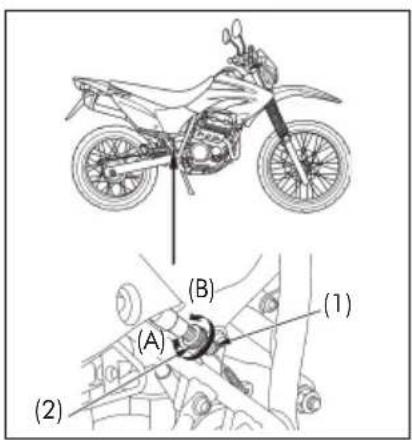
(1) Brake light switch (2) Adjusting nut
Bulb Replacement
(Refer to the Safety Precautions on page 55.)

CAUTION
The light bulb becomes very hot while the light is ON, and remains hot for a while after it is turned OFF. Be sure to let it cool down before servicing.
Do not put finger prints on the headlight bulb, as they may create hot spots on the bulb and cause it to break.
Wear clean gloves while replacing the bulb.
If you touch the bulb with your bare hands, clean it with a cloth moistened with alcohol to prevent its early failure.
■ Be sure to turn the ignition switch OFF when replacing the bulb.
■ Do not use bulbs other than those specified.
■ After installing a new bulb, check that the light operates properly.
Headlight Bulb
- Remove the bolts (1) and the headlight case (2).
- Disconnect the connector (3).
- Remove the seat rubber (4).
- Remove the headlight bulb (5) while pressing down on the pin (6).
- Install a new bulb in the reverse order of removal.
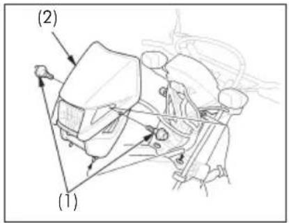
(1) Bolts
(2) Headlight case
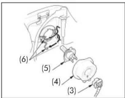
(3) Connector
(4) Seat rubber
(5) Headlight bulb
(6) Pin
Brake/Tail Light Bulb
- Remove the screws (1).
- Remove the brake/tail light lens (2).
- Slightly press the bulb (3) and turn it counterclockwise.
- Install a new bulb in the reverse order of removal.
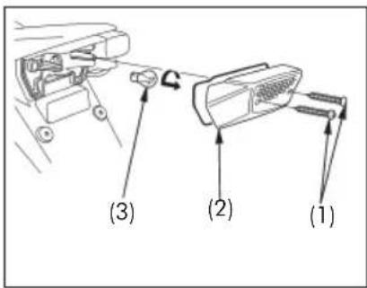
(1) Screws
(2) Brake/tail light lens
(3) Bulb
(Cont.)
Front/Rear Turn Signal Bulb
- Remove the screw (1) and the turn signal lens (2).
- Slightly press the bulb (3) and turn it counterclockwise.
- Install a new bulb in the reverse order of removal.
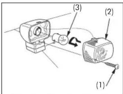
(1) Screw
(2) Turn signal lens
(3) Bulb
Headlight Aim Vertical Adjustment
(Refer to the Safety Precautions on page 55.)
Vertical adjustment can be made by turning the screw (1) in or out as necessary.
Obey local laws and regulations.
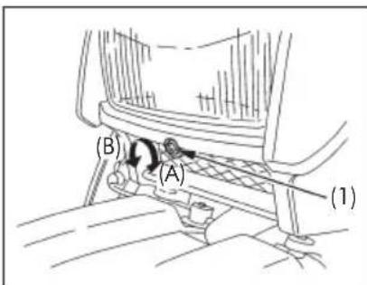
(1) Screw
(A) Up
(B) Down
CLEANING
Clean your motorcycle regularly to protect the surface finishes and inspect for damage, wear, and oil or brake fluid leakage.
Avoid cleaning products that are not specifically designed for motorcycle or automobile surfaces. They may contain harsh detergents or chemical solvents that could damage the metal, paint, and plastic on your motorcycle.
If your motorcycle is still warm from recent operation, give the engine and exhaust system time to cool off. We recommend avoiding the use of high pressure water spray (typical in coin-operated car washes).
NOTICE
High pressure water (or air) can damage certain parts of the motorcycle.
Washing the Motorcycle
- Rinse the motorcycle thoroughly with cool water to remove loose dirt.
- Clean the motorcycle with a sponge or soft cloth using cool water. Avoid directing water to muffler outlets and electrical parts.
- Clean the plastic parts using a cloth or sponge dampened with a solution of mild detergent and water. Rub the soiled area gently rinsing it frequently with fresh water. Take care to keep brake fluid or chemical solvents off the motorcycle. They will damage the plastic and painted surfaces.
- After cleaning, rinse the motorcycle thoroughly with plenty of clean water. Strong detergent residue can corrode alloy parts.
- Dry the motorcycle, start the engine, and let it run for several minutes.
- Test the brakes before riding the motorcycle. Several applications may be necessary to restore normal braking performance.
- Lubricate the drive chain immediately after washing and drying the motorcycle.

CAUTION
Braking efficiency may be temporarily impaired immediately after washing the motorcycle. Anticipate longer stopping distance to avoid a possible accident.
Finishing Touches
After washing your motorcycle, consider using a commercially-available spray cleaner/polish or quality liquid or paste wax to finish the job. Use only a non-abrasive polish or wax made specifically for motorcycles or automobiles. Apply the polish or wax according to the instructions on the container.
Removing Road Salt
Road Salt used on roads during winter and salt from seawater causes rust.
Wash your motorcycle as follows after it has run through salty water or on roads treated with Road Salt.
- Clean the motorcycle using cool water (page 85).
Do not use warm water.
This worsens the effect of the salt. - Dry the motorcycle and make sure of the metal is protected with the wax.
STORAGE GUIDE
Extended storage, such as for winter, requires that you take certain steps to reduce the effects of deterioration from non-use of the motorcycle. In addition, necessary repairs should be made BEFORE storing the motorcycle; otherwise, these repairs may be forgotten by the time the motorcycle is removed from storage.
Storage
- Change the engine oil and filter.
- Empty the fuel tank into an approved petrol container using a commercially available hand siphon or an equivalent method. Spray the inside of the tank with an aerosol rust-inhibiting oil.
Reinstall the fuel fill cap on the tank.
To assure proper performance after storage lasting more than one month, it is important to drain the carburetor.

WARNING
Petrol is highly flammable and explosive. You can be burned or seriously injured when handling fuel.
■ Stop the engine and keep heat, sparks, and flame away.
■ Refuel only outdoors.
■ Wipe up spills immediately.
- To prevent rusting in the cylinder, perform the following:
■ Remove the spark plug cap from the spark plug. Using tape or string, secure the cap to any convenient plastic body part so that it is positioned away from the spark plug.
■ Remove the spark plug from the engine and store it in a safe place. Do not connect the spark plug to the spark plug cap.
■ Pour a tablespoon (15 – 20 cm ^3 ) of clean engine oil into the cylinder and cover the spark plug hole with a piece of cloth.
■ Crank the engine several times to distribute the oil.
■ Reinstall the spark plug and spark plug cap.
(Cont.)
- Remove the battery. Store in an area protected from freezing temperatures and direct sunlight. Slow charge the battery once a month.
- Wash and dry the motorcycle. Wax all painted surfaces. Coat chrome with rustinhibiting oil.
- Lubricate the drive chain (page 73).
- Inflate the tyres to their recommended pressures. Place the motorcycle on blocks to raise both tyres off the ground.
- Cover the motorcycle (don't use plastic or other coated materials) and store in an unheated area, free of dampness with a minimum of daily temperature variation. Do not store the motorcycle in direct sunlight.
Removal from Storage
- Uncover and clean the motorcycle.
- Change the engine oil if more than 4 months have passed since the start of storage.
- Charge the battery as required. Install the battery.
- Drain any excess aerosol rust-inhibiting oil from the fuel tank. Fill the fuel tank with fresh petrol.
- Perform all Pre-ride Inspection checks (page 46). Test ride the motorcycle at low speeds in a safe riding area away from traffic.
TAKING CARE OF THE UNEXPECTED
If You Crash
Personal safety is your first priority after a crash. If you or anyone else has been injured, take time to assess the severity of the injuries and whether it is safe to continue riding. Call for emergency assistance if needed. Also follow applicable laws and regulations if another person or vehicle is involved in the crash. If you decide that you are capable of riding safely, first evaluate the condition of your motorcycle. If the engine is still running, turn it off and look it over carefully; inspect it for fluid leaks, check the tightness of critical nuts and bolts, and secure such parts as the handlebar, control levers, brakes, and wheels. If there is minor damage, or you are unsure about possible damage, ride slowly and cautiously. Sometimes, crash damage is hidden or not immediately apparent, so you should have your motorcycle thoroughly checked at a qualified service facility as soon as possible. Also, be sure to have your Honda dealer check the frame and suspension after any serious crash.
MOTORCYCLE IDENTIFICATION
Serial Numbers
The frame and engine serial numbers are required when registering your motorcycle.
They may also be required by your dealer when ordering replacement parts.
Record the numbers here for your reference.
FRAME NO. ____
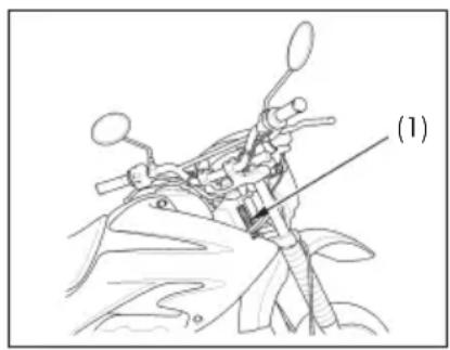
natural_image
Line drawing of a motorcycle's front view with no visible text or symbols(1) Frame number
The frame number (1) is stamped on the right side of the steering head.
ENGINE NO.
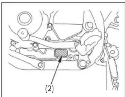
(2) Engine number
The engine number (2) is stamped on the left side of the crankcase.
Colour Label
The colour label (1) is attached to the left side of the frame.
It is helpful when ordering replacement parts. Record the colour and code here for your reference.
COLOUR:
CODE:
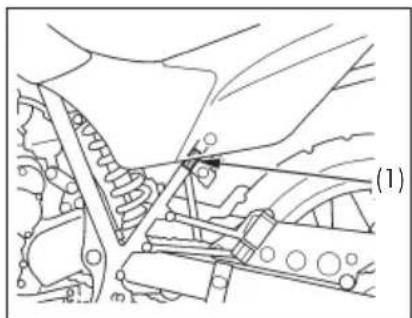
natural_image
Technical line drawing of a mechanical assembly with no visible text or symbols(1) Colour label
SPECIFICATIONS
| DIMENSIONS | |
| Overall length 2,147 mm (84.5 in) (with high seat) | 2,130 mm (83.9 in) (with low seat) |
| Overall width 845 mm (33.3 in) | |
| Overall height 1,203 mm (47.4 in) (with high seat) | 1,166 mm (45.9 in) (with low seat) |
| Wheelbase 1,427 mm (56.2 in) (with high seat) | 1,416 mm (55.7 in) (with low seat) |
| Ground clearance 281 mm (11.1 in) (with high seat) | 242 mm (9.53 in) (with low seat) |
| Seat height 880 mm (34.6 in) (with high seat) | 840 mm (33.1 in) (with low seat) |
| WEIGHT | |
| Dry weight 134 kg (295 lbs) | |
CAPACITIES
Engine oil After draining 1.4 liter (1.5 US qt, 1.2 Imp.qt)
After draining and oil filter change 1.5 liter (1.6 US qt, 1.3 Imp.qt)
After disassembly 1.8 liter (1.9 US qt, 1.6 Imp.qt)
Fuel tank 11.5 liters (3.04 US gal, 2.53 Imp.gal)
Fuel reserve 3.7 liters (0.98 US qt, 0.81 Imp.qt)
Passenger capacity Operator and passenger
Maximum load capacity 153 kg (337 lbs)
ENGINE
| Type DOHC, single cylinder, 4 stroke, four-valve, air cooled with oil cooler | |
| Cylinder arrangement Inclined 15° regarding the vertical position | |
| Bore and stroke 73.0 x 59.5 mm (2.90 x 2.34 in) | |
| Displacement 249 cm | ^3 (15.2 cu-in) |
| Compression ratio 9.3 : 1 | |
| Maximum horsepower | 23.3 HP at 7,500 min ^-1 (rpm) |
| Maximum torque | 2.42 kgf.m at 6,000 min ^-1 (rpm) |
| Spark plug Standard CR8EH – 9S (NGK) | |
| For extended high speed riding CR9EH – 9S (NGK) – Optional | |
| Spark plug gap 0.8 – 0.9 mm (0.031 – 0.035 in) | |
| Idle speed | 1,400 ± 100 min ^-1 (rpm) |
| Valve clearance (cold) IN | 0.12 mm (0.005 in) |
| EX 0.15 mm (0.006 in) | |
CHASSIS AND SUSPENSION
| Caster 25°58′ (with high seat) | |
| 26°9′ (with low seat) | |
| Trail 98 mm (3.9 in) (with high seat) | 100 mm (3.9 in) (with low seat) |
| Front tyre (size) 90/90–21M/C 54S | (brand model) METZELER ENDURO 3 |
| Rear tyre (size) 120/80–18M/C 62S | (brand model) METZELER ENDURO 3 |
| Tyre type Bias-ply, tube | |
| Front suspension (type) | Telescopic fork |
| (travel: damper/axle) | 245 mm (9.65 in) / 220 mm (8.66 in) |
| Rear suspension (type) | Pro-Link |
| (travel: shock absorver/axle) | 82.8 mm (3.26 in) / 242 mm (9.53 in) |
| Front brake (type) Hydraulic single disc brake | |
| Rear brake (type) Drum (internal expanding shoes) | |
POWER TRANSMISSION
| Type Constant mesh, 6-speed | |
| Clutch Multi-plate, wet-type | |
| Primary reduction 3.100 | |
| Final reduction 2.923 | |
| Gear ratio 1st 2.769 | |
| 2nd 1.777 | |
| 3rd 1.333 | |
| 4th 1.083 | |
| 5th 0.923 | |
| 6th 0.814 | |
| Gearshift system | Left foot operated return system |
ELECTRICAL
| Battery 12 V – 6 Ah |
| Generator |
| Main fuse 20 A |
| Other fuses 10 A, 15 A |
LIGHTS
| Headlight (high/low) 12 V – 35/35 W |
| Brake/tail light 12 V – 21/5 W |
| Turn signal light 12 V – 10 W x 4 |
| Speedometer light LED |
| Turn signal indicator LED |
| Neutral indicator LED |
| High beam indicator LED |
HONDA
The Power of Dreams
XR250 Tornado
?
- XR250 TORNADO
- Bienvenido
- Tanque de Combustible
- ESPECIFICACIONES
- Welcome
- Important Information
- ■ OPERATOR AND PASSENGER
- ■ ON/OFF-ROAD USE
- ■ READ THIS OWNER'S MANUAL CAREFULLY
- A Few Words About Safety
- WARNING
- CAUTION
- OPERATION
- MOTORCYCLE SAFETY 09
- PARTS LOCATION 15
- MAJOR COMPONENTS 29
- (Information you need to operate this motorcycle)
- ESSENTIAL INDIVIDUAL COMPONENTS 40
- FEATURES 43
- (Not required for operation)
- OPERATION 46
- MAINTENANCE 53
- CLEANING 85
- STORAGE GUIDE 87
- TAKING CARE OF THE UNEXPECTED 89
- MOTORCYCLE IDENTIFICATION 89
- SPECIFICATIONS 91
- MOTORCYCLE SAFETY
- Important Safety Information
- Always Wear a Helmet
- Make Yourself Easy to See On-Road
- Be Alert for Off-Road Hazards
- Ride Within Your Limits
- Keep Your Bike in Safe Condition
- Don't Drink and Ride
- Protective Apparel
- Helmets and Eye Protection
- Additional On-Road Gear
- Additional Off-Road Gear
- Load Limits and Guidelines
- Loading
- Load Limit
- Loading Guidelines
- Accessories and Modifications
- Accessories
- Modifications
- Off-Road Safety
- PARTS LOCATION
- Instruments and Indicators
- Initial Display
- Multi-function Display
- Speedometer
- Odometer
- Tripmeter
- TRIP 1 and TRIP 2
- To reset
- To change mileage reading
- To subtract mileage
- Example:
- To start subtraction
- To stop subtraction
- —TRIP
- Mode selection
- How to set distance
- Digital Clock and Elapsed Time Meter
- Digital Clock
- Elapsed Time Meter
- To stop/restart counting
- MAJOR COMPONENTS
- Brakes
- Front Brake
- Brake Fluid Level
- Other Checks
- Rear Brake
- Brake Adjustment
- Clutch
- NOTICE
- Fuel
- Fuel Valve
- OFF
- ON
- RES
- Fuel Tank
- Petrol Containing Alcohol
- Engine Oil
- Engine Oil Level Check
- Tyres
- Air Pressure
- Inspection
- Tread Wear
- Tube Repair and Replacement
- Tyre Replacement
- ESSENTIAL INDIVIDUAL COMPONENTS
- Ignition Switch
- Right Handlebar Controls
- Engine Stop Switch
- Start Button
- Left Handlebar Controls
- Headlight Dimmer Switch (1)
- Turn Signal Switch (2)
- Horn Button (3)
- FEATURES
- Steering Lock
- Helmet Holder
- Side Cover
- Removal
- Installation
- Document Compartment
- Height Modification
- (High seat type and Low seat type)
- Pre-ride Inspection
- Starting the Engine
- Preparation
- Starting Procedure
- Warm Engine
- Flooded Engine
- Running-in
- Riding
- Shifting
- Upshifting
- Downshifting
- Braking
- Important Safety Reminders
- Parking
- Anti-theft Tips
- MAINTENANCE
- The Importance of Maintenance
- Maintenance Safety
- ! WARNING
- Safety Precautions
- Maintenance Schedule
- Tool Kit
- Air Cleaner
- Crankcase Breather
- JASO T 903 Standard
- Engine Oil and Filter
- Spark Plug
- Valve Clearance
- Throttle Operation
- Idle Speed
- Drive Chain
- SPROCKETS
- Adjustment
- Wear inspection
- mm (2.4 in)
- Lubrication and Cleaning
- Drive Chain Slider
- Front and Rear Suspension Inspection
- Side Stand
- Functional Check
- Wheels
- Front Wheel Removal
- Installation Notes
- N.m (6.0 kgf.m; 44 lbf.ft)
- N.m (1.2 kgf.m; 9 lbf.ft)
- Rear Wheel Removal
- N.m (9.0 kgf.m; 65 lbf.ft)
- Brake Pad Wear
- Brake Shoe Wear
- Battery
- Fuse Replacement
- Fuse Box
- Main Fuse
- Brake Light Switch Adjustment
- Bulb Replacement
- Headlight Bulb
- Brake/Tail Light Bulb
- Front/Rear Turn Signal Bulb
- Headlight Aim Vertical Adjustment
- CLEANING
- Washing the Motorcycle
- Finishing Touches
- Removing Road Salt
- STORAGE GUIDE
- Storage
- Removal from Storage
- TAKING CARE OF THE UNEXPECTED
- If You Crash
- MOTORCYCLE IDENTIFICATION
- Serial Numbers
- Colour Label
- CAPACITIES
- HONDA
Brand : Honda
Model : XR250 Tornado (2017)
Category : Motorcycle