
SUW200 - Wall mount SONY - Free user manual and instructions
Find the device manual for free SUW200 SONY in PDF.
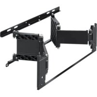
| Product Type | Wall mount |
| Brand | Sony |
| Model | SUW200 |
| Compatibility | Sony 23-inch LCD color TV |
| Support weight | 2.1 kg |
| Maximum supported load | 10 kg |
| Adjustable tilt angles | 0°, 5°, 10°, 15° |
| Material | Steel |
| Package contents | Supports A, B, C, 4 screws with washers |
| Wall fixation | 4 screws (not supplied) suitable for the wall |
| Fixation to TV | 4 original TV screws |
| Installation required | Technical experience recommended, call a professional |
| Safety | Do not stand on the TV; check wall strength; do not exceed maximum load |
| Maintenance | Clean with a soft dry cloth |
| Repairability | Not user repairable; do not disassemble or modify |
| Warranty | Consult Sony warranty conditions |
| Standards | Compliant with applicable safety requirements |
| Intended use | Wall mounting of a specific TV |
Frequently Asked Questions - SUW200 SONY
User questions about SUW200 SONY
0 question about this device. Answer the ones you know or ask your own.
Ask a new question about this device
Download the instructions for your Wall mount in PDF format for free! Find your manual SUW200 - SONY and take your electronic device back in hand. On this page are published all the documents necessary for the use of your device. SUW200 by SONY.
USER MANUAL SUW200 SONY
Operating Instructions
This Wall-Mount Bracket is designed for use only with a Sony 23-inch LCD Color TV that specifies the use of the Bracket in its Operating Instructions.
To Customers
Sufficient expertise is required for installing this product. Be sure to subcontract the installation to Sony dealers or contractors and pay adequate attention to safety during the installation.
Mode d'emploi
Thank you for purchasing this product.
To Customers
Sufficient expertise is required for installing this product. Be sure to subcontract the installation to Sony dealers or contractors and pay adequate attention to safety during the installation. We are not liable for any damage or injury caused by mishandling or improper installation. Your Statutory Rights (if any) are not affected.
WARNING
To avoid risk of serious injury or damage to the TV caused by dropping it, observe the following precautions.
- Do not hang from the TV or the Wall-Mount Bracket installed on the wall.
- Be careful not to trap the AC power adaptor cord of the TV when you secure the TV to the Wall-Mount Bracket.
- Follow the installation procedures and installation direction described in this manual.
For a safety installation, consult your Sony dealer or qualified service personnel. - Before installing, confirm that the wall has sufficient strength to support the TV and the Wall-Mount Bracket. The installation location should be a flat, perpendicular wall with a reinforcing material inside.
- Do not apply a weight other than the TV to the Wall-Mount Bracket installed on the wall.
- Do not disassemble, modify or change the parts of the Wall-Mount Bracket.
For Sony Dealers
Sufficient expertise is required for installing this product. Be sure to read this instruction manual thoroughly to do the installation work safely. We are not liable for any damage or injury caused by mishandling or improper installation. After installation, please hand this installation manual to the customers.
Caution
- This Wall-Mount Bracket is only for Sony 23-inch LCD Color TVs.
Do not use the bracket with a TV whose operating instructions do not specify the use of this bracket. - Be especially careful not to drop the TV when you install it high on a wall.
Installation
For Sony Dealers
For the installation, have ready eight commercially available mounting screws, anchor bolts, etc. that are appropriate for the wall.
The type and length of the screws required depend on the material and strength of the wall. If you do not know which material your wall is made of, consult your Sony dealer or qualified service personnel.
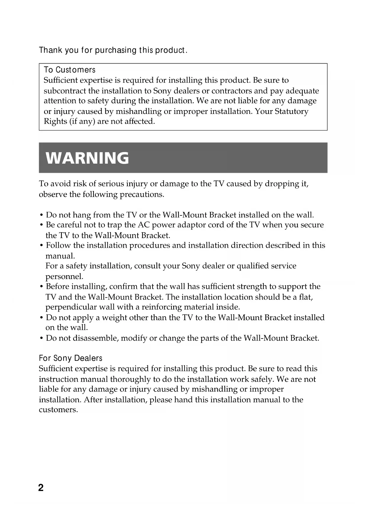
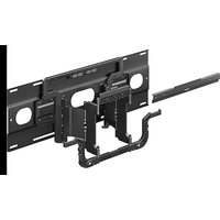
Step 1: Check the parts
Check all the parts are included in the package.
Bracket A (1)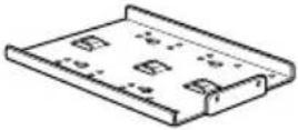 | Bracket B (1)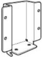 | Bracket C (1) | Screw (4)(with a washer) |
Step 2: Decide the installation location
Decide the location on the wall to install the TV.
Then, place bracket Ⓐ on the installation location and mark the four screw holes on the wall using a pencil.
Before marking the location of the holes, make sure that the distance between the upper edge of bracket Ⓐ and the ceiling is 20 cm (7 7/8 inches) or more, and that between the side edge of bracket Ⓐ and the side wall is 25 cm (9 7/8 inches) or more.
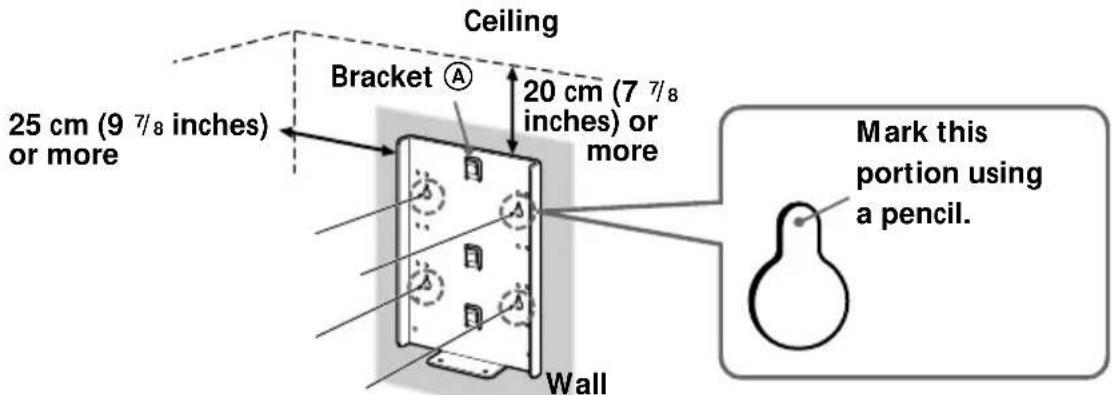
Note
Attach bracket Ⓐ level with the floor.
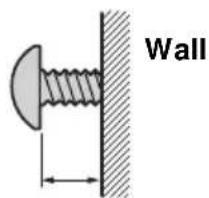
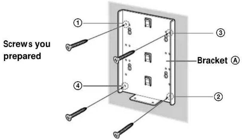
Step 3: Secure bracket Ⓐ to the wall
1 Insert four of the screws you prepared at the positions marked in Step 2 (page 4).
Do not tighten the screws completely for the moment. Keep a space of 2 to 3 ~mm (3/32 to 1/8 inches) from the wall.
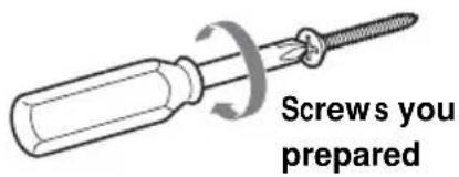
2 - 3 mm ( ^3/32-^1/8 inches)
2 Press bracket Ⓐ to the wall and slide it down. Then fully tighten the four screws on the wall.
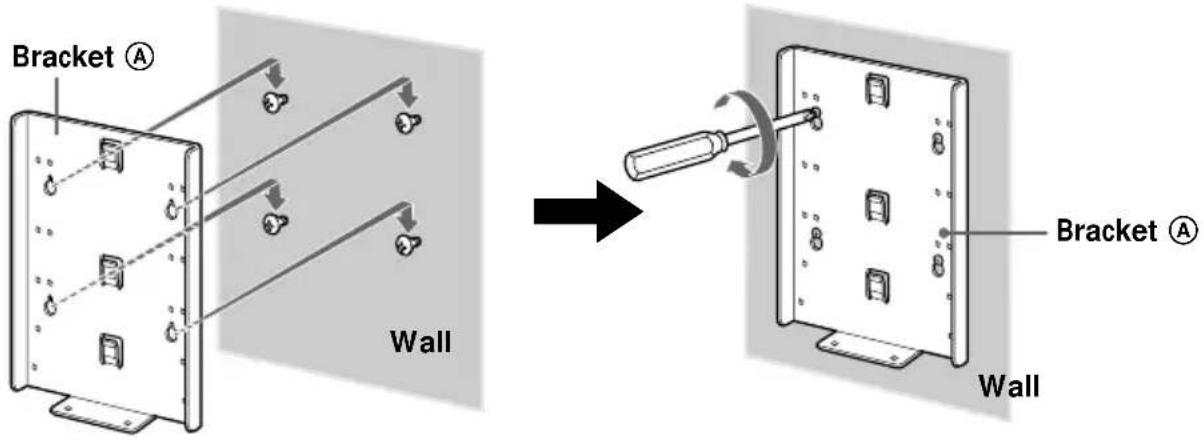
3 Fully tighten four of the screws you prepared in screw holes ① to ④ firmly.
continued
Step 4: Attach bracket Ⓑ to the TV
Before attaching bracket Ⓑ, disconnect the AC power adaptor and all the cables from the TV.
For how to remove the rear cover of the TV, refer to the Operating Instructions supplied with the TV.
1 Remove the four screws as illustrated below, and detach the TV stand from the TV.
To prevent damaging the surface of the LCD display, place the TV on a soft mat.
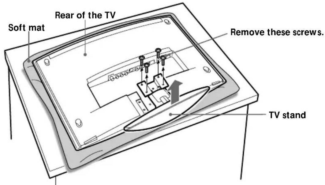
Notes
- Place the TV body only on the table as illustrated above. If the TV stand is also on the table level to the TV body, the TV body may become unstable and cause damage.
- When removing the TV stand, hold it firmly.
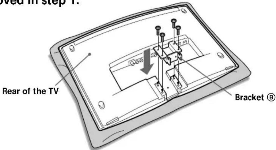
2 Secure bracket Ⓑ to the TV firmly using the four screws removed in step 1.
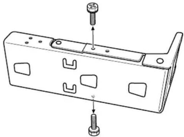
Step 5: Attach bracket © to the TV
You can adjust the angle of the Wall-Mount Bracket to one of four different angles (0, 5, 10 or 15 degrees). Change the position of the stay according to the desired angle. (If you choose 0 degrees, there is no need to change the position of the stay.)
Remove the two screws as illustrated below.
natural_image
Technical line drawing of a mechanical bracket with two bolts and cutouts, no text or symbols present2 Pull out the stay as illustrated below.
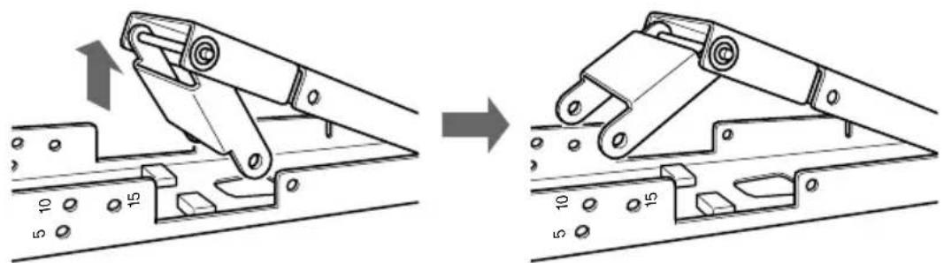
natural_image
Mechanical assembly diagram showing a bracket being lifted by a crane, with no visible text or symbols3
Align the screw holes of the stay with the holes corresponding to the desired angle on bracket ©, and secure the stay using the two screws removed in step 1.
The illustration below shows how to align the holes when you choose an angle of 10 degrees.
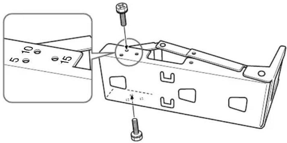
Note
Be careful not to get your fingers pinched between the stay and the bracket.
4
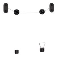
Connect the cables to the TV so that they pass along the sides of bracket Ⓑ.
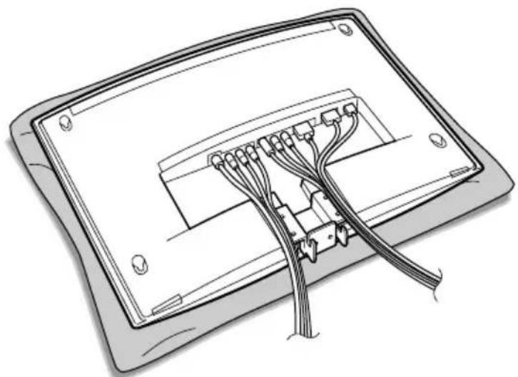
natural_image
Diagram of a device's internal cable structure with connectors and wiring (no text or symbols)5
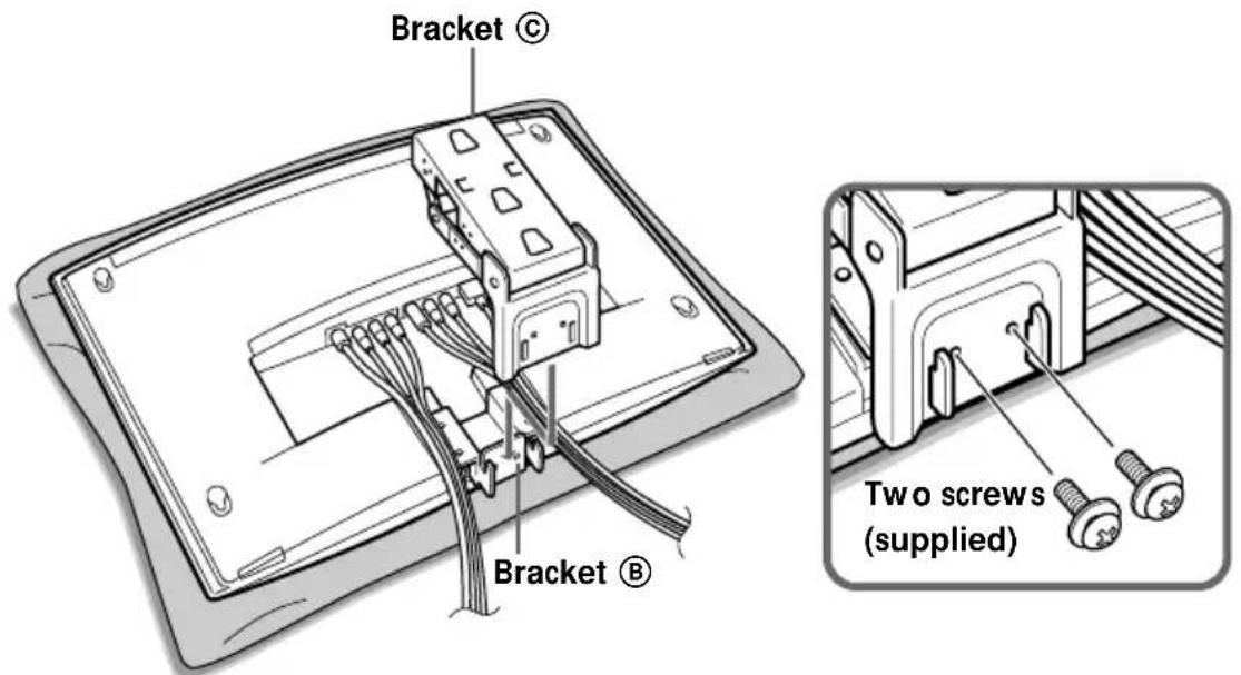
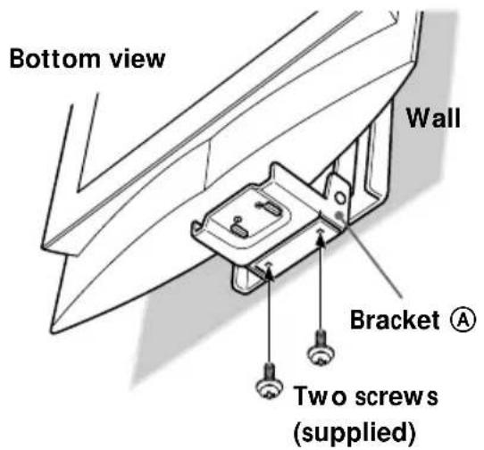
Fix bracket Ⓐ into bracket Ⓑ as illustrated below, and secure them firmly using the two screws supplied.
Step 6: Secure the TV to the wall
1
Hook bracket © on bracket Ⓐ.
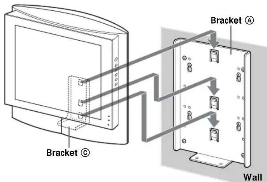
Notes
- Secure the TV to the wall without the rear cover.
- Hold the TV firmly. Be especially careful when you secure the TV in a high place.
- Do not release the TV until you confirm that bracket Ⓒ is firmly secured to bracket Ⓓ at three locations.
continued
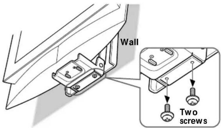
2 Align the screw holes on bracket Ⓒ with those on bracket Ⓐ, and fully tighten the two screws supplied.
Step 7: Replace the rear cover on the TV
For details on how to replace the rear cover, refer to the Operating Instructions of the TV.
Detaching the TV from the Wall-Mount Bracket
To detach the TV, remove the rear cover from the TV, then remove the two screws.
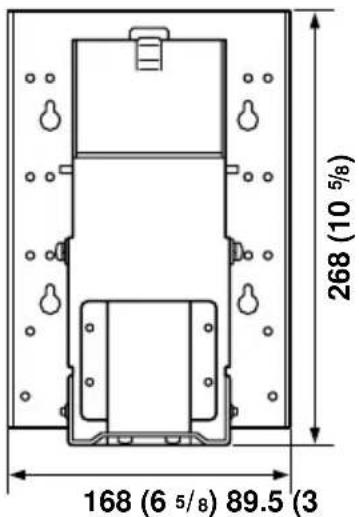
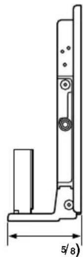
Specifications
natural_image
Technical line drawing of a mechanical bracket with dimension label (5/8) and mounting holes, no readable text or symbols beyond the measurement.Unit: mm (inches)
Bracket mass:
Approx. 2.1 kg (4 lb 10 oz)
Supportable weight:
Approx. 10 kg (22 lb 1 oz)
Design and specifications are subject to change without notice.
natural_image
Technical line drawing of a mechanical bracket with two bolts inserted, showing internal cutouts and mounting holes (no text or symbols)2
natural_image
Mechanical assembly diagram showing a bracket being lifted or mounted, with no visible text or symbols3
natural_image
Diagram of a device's internal cable structure with multiple connectors (no text or symbols)5
natural_image
Technical line drawing of a mechanical bracket with dimension label (5/8) and mounting holes, no readable text or symbols beyond the measurement.Unité : mm (pouces)
natural_image
Technical line drawing of a mechanical bracket with two bolts inserted, showing mounting holes and fasteners (no text or symbols)natural_image
Mechanical assembly diagram showing a bracket being lifted by a crane, with no visible text or symbols3
Nota
natural_image
Diagram of a device showing internal cable connections into a rectangular panel (no text or symbols)5
Notas
natural_image
Technical line drawing of a mechanical bracket with dimension label (5/8) and mounting holes, no readable text or symbols beyond the measurement.Printed on 100% recycled paper using VOC (Volatile Organic Compound)-free vegetable oil based ink.

- Operating Instructions
- To Customers
- Mode d'emploi
- WARNING
- For Sony Dealers
- Caution
- Installation
- Step 1: Check the parts
- Step 2: Decide the installation location
- Note
- Step 3: Secure bracket Ⓐ to the wall
- Insert four of the screws you prepared at the positions marked in Step 2 (page 4).
- Press bracket Ⓐ to the wall and slide it down. Then fully tighten the four screws on the wall.
- Fully tighten four of the screws you prepared in screw holes ① to ④ firmly.
- Step 4: Attach bracket Ⓑ to the TV
- Remove the four screws as illustrated below, and detach the TV stand from the TV.
- Notes
- Secure bracket Ⓑ to the TV firmly using the four screws removed in step 1.
- Step 5: Attach bracket © to the TV
- Remove the two screws as illustrated below.
- Pull out the stay as illustrated below.
- 3
- 4
- 5
- Step 6: Secure the TV to the wall
- 1
- Step 7: Replace the rear cover on the TV
- Detaching the TV from the Wall-Mount Bracket
- Specifications
- Nota
- Notas
Brand : SONY
Model : SUW200
Category : Wall mount