55013080 - Smart Home Niko - Free user manual and instructions
Find the device manual for free 55013080 Niko in PDF.
| Product type | Eco screen for smart home |
| Brand | Niko |
| Model | 55013080 |
| Category | Smart home |
| Dimensions (H x W x D) | 45 x 45 x 32 mm |
| Recess depth | 20 mm |
| Estimated weight | 100 g |
| Power supply | 26 Vdc (SELV) via Niko Home Control bus |
| Operating temperature | 5 °C to 45 °C |
| Protection rating | IP20 |
| Display | Illuminated color |
| Main functions | Display consumption (electricity, water, gas), electricity production, activation of eco function, presence simulation |
| Standards | IEC60730-2-9, EN 50491-5-2, EN 50491-2, EN 50090-2-3 |
| Installation | On recessed box, with bridge and cover plate |
| Maintenance and cleaning | Clean with a soft, dry cloth |
| Safety | Safety extra-low voltage (SELV) |
| Spare parts | Contact Niko after-sales service |
| Repairability | Repair by an approved professional |
| Compatibility | Niko Home Control system |
| Keys | 3 keys (eco, presence simulation, navigation/confirmation) |
Frequently Asked Questions - 55013080 Niko
User questions about 55013080 Niko
0 question about this device. Answer the ones you know or ask your own.
Ask a new question about this device
Download the instructions for your Smart Home in PDF format for free! Find your manual 55013080 - Niko and take your electronic device back in hand. On this page are published all the documents necessary for the use of your device. 55013080 by Niko.
USER MANUAL 55013080 Niko
Three types of push buttons with display are available:
- mood setting display
- thermostat
- eco-display
Installation
Push buttons with display are integrated in a bridge. The bridge is mounted onto a standard flush-mounting box using screws.
1 Connect the push button to the two-wire bus cable using the double plug-in connector (marked BB) on the back of the control element. Connect each wire separately to one of the contacts.

- Strip the wires of the bus cable 9 - 10 mm.
- A maximum of two wires with a diameter of 0.5 - 1 mm each can be connected per contact.
The push button with display is now connected. Use the other opening of the contact to establish a connection to the next control element if required.
2 Mount the bridge onto the single flush-mounting box using screws in order to secure the push button with display. Use a bridge with a set of claws if no screw holes are provided in the flush-mounting box. Three types of bridges are available:
bridge 60 x 71 mm with claw connection
bridge 71× 71mm with screw connection
bridge 60× 71mm with screw connection
3 Complete the installation using a flush surround plate from our series Niko Pure, Niko Intense or Niko Original.
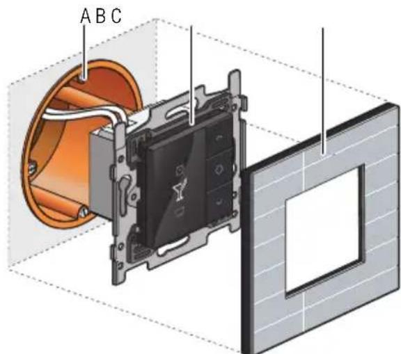
Installation diagram for push button with display
A. Single flush-mounting box (not a Niko product)
B. Push button with display
C. Flush surround plate
6.1. Mood setting display
Description
The mood setting display is used by the resident to select one of the pre-programmed mood settings. A mood setting is a combination of output settings with regard to lighting, roll-down shutters, sun blinds, etc.
Overview
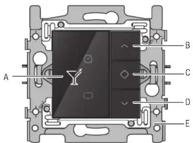
550-13040
A. Display
B. Navigation button (up)
C. Activate
D. Navigation button (down)
E. Bridge
Operation
Mood settings are stored during the programming stage of the installation. The software includes 20 pictograms of which a maximum of eight pictograms can be selected. One or more actions are then linked to each one of those eight pictograms to help create the ideal mood for each occasion.
To activate a mood setting:
1 Touch one of the buttons to light up the display. When not in use, the display is dimmed to reduce energy consumption.
2 Press the navigation buttons until the pictogram appears for the mood setting of your choice.
3 Press button "C".
The pictogram will change to an amber colour and will remain that way for as long as the mood setting is activated.

Mood settings can also be activated by sensors integrated in the Niko Home Control installation. You can select this option while programming the installation.
Installation
See Installation on page 30.
Technical data
- back-lit colour display
- resting potential: 26 Vdc (SELV, safety extra-low voltage)
- ambient temperature: 0 - 50^ C
- dimensions of the display: 45 × 45 × 32 mm (HxWxD)
- flush-mounting depth: 20mm
6.2. Thermostat
Description
Using the thermostat function, you can select heating or cooling options for several different zones or rooms. The thermostat operates in conjunction with a heating or cooling module. See Heating or cooling module on page 103
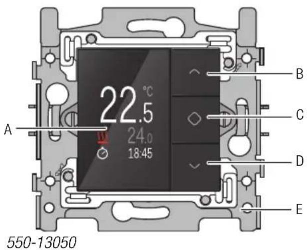
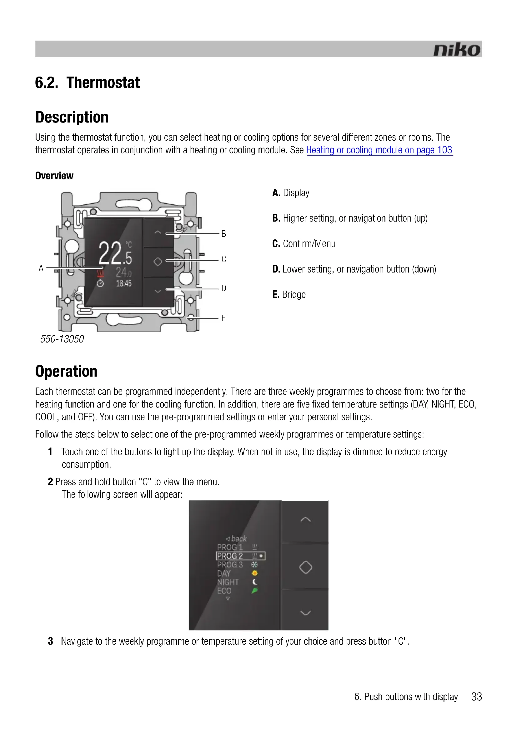
Overview
A. Display
B. Higher setting, or navigation button (up)
C. Confirm/Menu
D. Lower setting, or navigation button (down)
E. Bridge
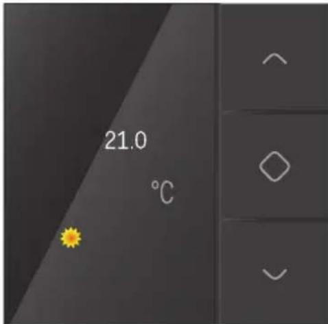
Operation
Each thermostat can be programmed independently. There are three weekly programmes to choose from: two for the heating function and one for the cooling function. In addition, there are five fixed temperature settings (DAY, NIGHT, ECO, COOL, and OFF). You can use the pre-programmed settings or enter your personal settings.
Follow the steps below to select one of the pre-programmed weekly programmes or temperature settings:
1 Touch one of the buttons to light up the display. When not in use, the display is dimmed to reduce energy consumption.
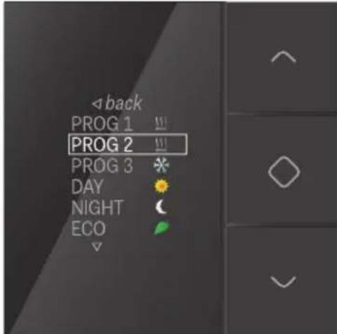
2 Press and hold button "C" to view the menu. The following screen will appear:
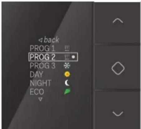
3 Navigate to the weekly programme or temperature setting of your choice and press button "C".
The following temperature factory settings are pre-programmed into the system:
The following weekly programmes are pre-programmed into the system:
| PROG1 Weekday | 06:00 => 08:00 DAY 08:00 => 16:00 NIGHT 16:00 => 18:00 ECO 18:00 => 22:00 DAY 22:00 => 06:00 NIGHT Weekend: 08:00 => 22:00 DAY 22:00 => 08:00 NIGHT |
| PROG2 Weekday: | 08:00 => 22:00 DAY 22:00 => 08:00 NIGHT Weekend: 08:00 => 22:00 DAY 22:00 => 08:00 NIGHT |
| PROG3 Weekday: | 16:00 => 19:00 COOL 19:00 => 16:00 OFF Weekend: 10:00 => 19:00 COOL 19:00 => 10:00 OFF |
Residents can modify these settings according to their needs.
Modifying pre-programmed settings
To modify one of the pre-programmed settings:
1 Touch one of the buttons to light up the display. When not in use, the display is dimmed to reduce energy consumption.
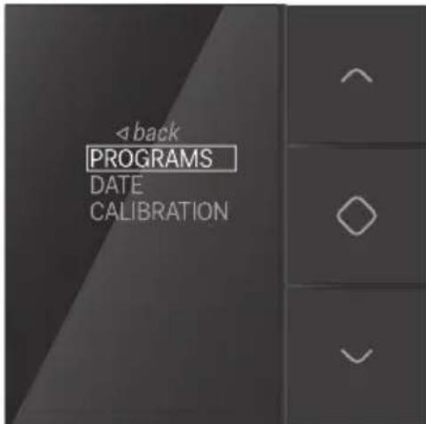
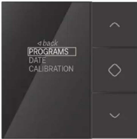
2 Press button "C" until the following screen appears:
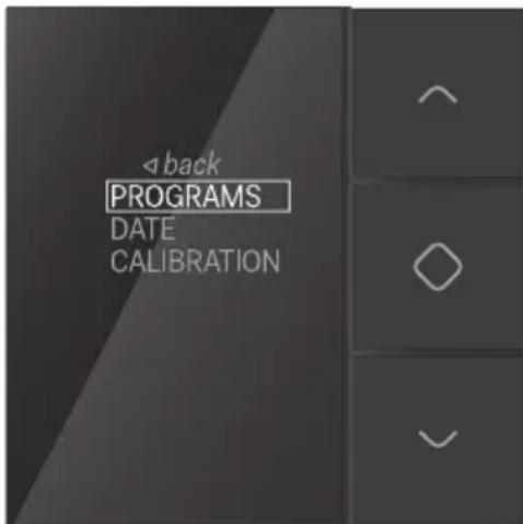
3 Make sure PROGRAMS is selected and press button "C".
The following screen will appear:
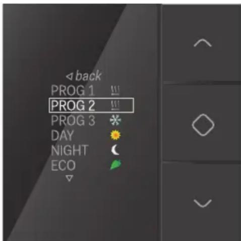
You can now select and modify the weekly programme or temperature level of your choice.
Modifying fixed temperature settings
To modify one of the fixed temperature settings:
1 Navigate to the temperature setting you wish to modify.
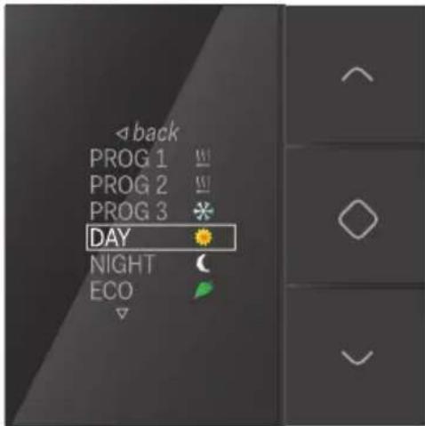
2 Press button "C".
The following screen will appear:
3 Enter the temperature setting of your choice using the navigation buttons. Press button "C". The new temperature setting is now saved and you will be redirected to the previous screen.
Modifying weekly programmes
Weekly programmes include one or more daily programmes. These can be modified or added individually.
To select a daily programme:
1 Navigate to the weekly programme you wish to modify.
2 Press button "C".
The following screen will appear:
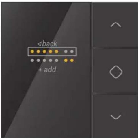
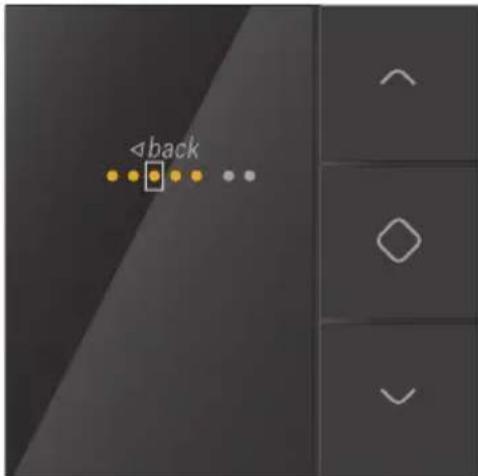
On this screen, the top row represents the week while the bottom row represents the weekend.
3 Select either the week or the weekend if you wish to modify an existing daily programme.
Select add if you wish to add a new daily programme.
4 Press button "C".
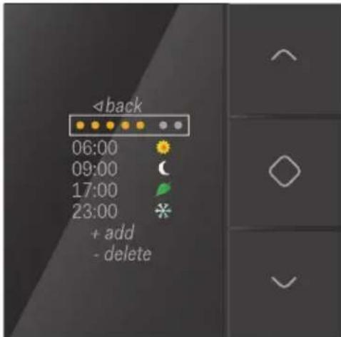
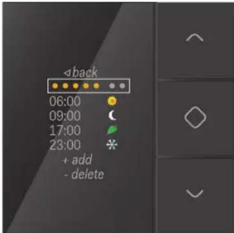
The daily programme will appear:
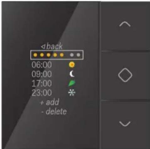
You can now modify the daily programme, add new time and temperature settings, or delete existing settings.
To modify a daily programme:
1 Select week or weekend and press button "C". The following screen will appear:
2 Use the navigation buttons to navigate the days of the week. Press button "C" to activate or deactivate the days of your choice.
3 Select back using the navigation buttons and press button "C". The following screen will appear:
4 Select the time and temperature setting you wish to modify and press button "C". The following screen will appear:
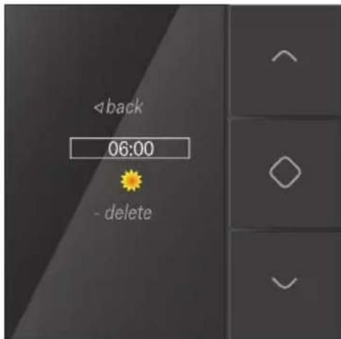
5 Enter the new time setting using the navigation buttons. Press button "C" when you have completed the process.
6 Select the new temperature setting and press button "C".
The following screen will appear:
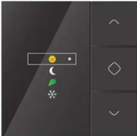
If you do not select a temperature setting, the system will automatically select OFF.
The new temperature setting is now saved and you will be redirected to the previous screen.
7 Select back until you reach the following screen:
8 Repeat steps 4 to 7 for each time setting and temperature setting you wish to modify or add.
Setting the date and time

- Date and time settings that are modified via the thermostat will apply to the entire Niko Home Control installation.
- The date and time can also be modified via the programming or user software.
1 Select DATE on the following screen:
2 Press button "C".
You can now modify the year, month, day, hour and minutes.
3 Select the settings you wish to modify and press button "C".
4 Use the navigation buttons to enter a new setting and press button "C".
5 Select back using the navigation buttons and press button "C".
Calibrating the clock thermostat
If the thermostat temperature differs from the actual temperature, the thermostat must be calibrated.

- Only calibrate the thermostat after the installation has been in use for at least two hours as this will ensure that the temperature displayed has stabilised.
- Do not calibrate the thermostat temperature under extreme temperature conditions.
1 Measure the temperature in the centre of the room using a thermometer.
2 Select CALIBRATION on the following screen:
3 Press button "C".
4 Use the navigation buttons until the temperature on the display corresponds to the temperature measured in the centre of the room. Press button "C".

You can increase or decrease the temperature on the display by six degrees.
5 Select back using the navigation buttons and press button "C".
Installation
A thermostat can be mounted in any room fitted with a floor-heating system, radiator, heating unit or cooling unit. It controls the heating or cooling for the room in which it is mounted.
The thermostat only functions properly when the temperature within the room can be measured accurately. Try to eliminate as many factors as you can that may inhibit the thermostat's ability to accurately control the room temperature.
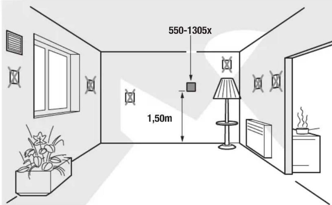

DO NOT mount the thermostat:
- in direct sunlight.
on an exterior wall. - within the immediate vicinity of a heat generating source (heater, radiator, etc.) or electrical equipment that may radiate heat (TV, computer, etc.).
behind a curtain.
Do not allow air to circulate behind the thermostat. If needed, fill in any gaps in the flush-mounting box or bus cable duct using PU foam.
See Installation on page 30.
Technical data
- back-lit colour display
- resting potential: 26 Vdc (SELV, safety extra-low voltage)
ambient temperature: 5 - 40°C - dimensions of the display: 45 × 45 × 32 mm (HxWxD)
- flush-mounting depth: 20 mm
daily/weekly programmes - 5 temperature settings: day, night, eco, off (frost-free) and cool
temperature accuracy: 0.5^ - in conformity with IEC60730-2-9, EN 50491-5-2, EN 50491-2 and EN 50090-2-3
- protection rating: IP20
6.3. Eco-display
Description
The eco-display allows residents to monitor the energy and water consumption as well as the amount of energy generated (if applicable) in their home. It can also be used to activate the eco-function or presence simulation function.
Overview
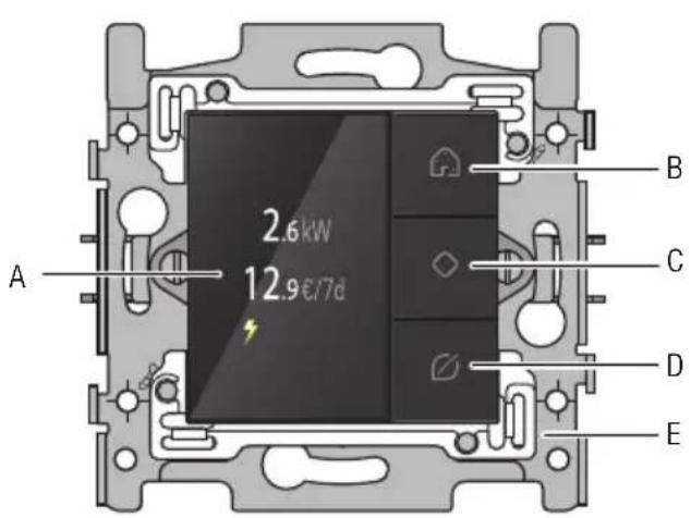
550-13080
A. Display
B. Presence simulation button
C. Confirm/Menu/Cycle through screens
D.Eco-button
E. Bridge
Operation
Consumption details
The eco-display shows information on the electricity, gas and water consumption as well as the electricity production in the home. See Electricity measuring modules on page 58. The type of information displayed will depend on the types of measuring modules installed. The electricity measuring module measures the electricity consumption or electricity production. The pulse counter communicates the electricity, gas and water consumption.
The current electricity consumption is expressed in W or kW, while gas consumption is expressed in m³. The total energy consumption for that week expressed in EUR or GBP is displayed underneath.
To view the rates:
1 Touch one of the buttons to light up the display. When not in use, the display is dimmed to reduce energy consumption.
2 Press and hold button "C" to view the menu. The following screen will appear:
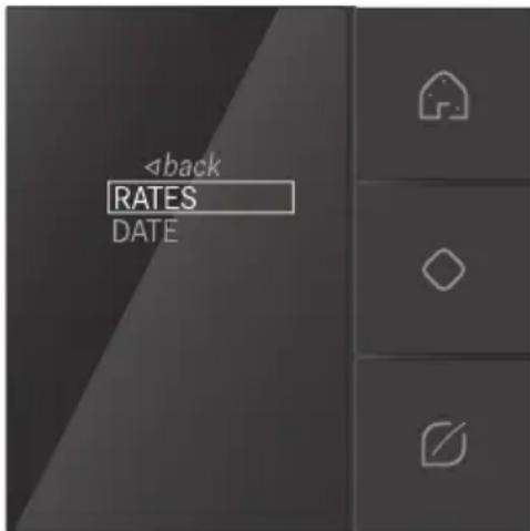
3 Press button "C" to select RATES. The following screen will appear:
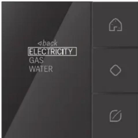
4 Select ELECTRICITY, GAS or WATER and press button "C". The selected rate will appear. You can modify the rate at this stage.
5 Select back using the navigation buttons and press button "C".
Eco-function
The eco-function applies to all the lights and connected circuits that the resident wishes to switch off upon leaving the home. You can determine the outputs that are to be included in this function while programming the installation.
Press the eco-button to activate the eco-function. The reduction in energy consumption will be registered immediately.
Presence simulation
The presence simulation function allows the resident to have the lights switch on automatically at certain times. This way, it looks as though someone is home. While programming the installation, you can personally determine which lights should be included in the presence simulation as well as when they should switch on and how long they should be left on for.
Press the presence simulation button to activate the presence simulation function.
Installation

Mount the eco-display:
away from direct sunlight.
- near the door most commonly used by the resident to exit the home.
See Installation on page 30.
Technical data
- back-lit colour display
- resting potential: 26 Vdc (SELV, safety extra-low voltage)
- ambient temperature: 5 - 45^ C
- dimensions of the display: 45 × 45 × 32 mm (HxWxD)
- flush-mounting depth: 20 mm
- weekly energy consumption in EUR or GBP
- in conformity with IEC60730-2-9, EN 50491-5-2, EN 50491-2 and EN 50090-2-3