M09ACS Machflow - Hand dryer Mediclinics - Free user manual and instructions
Find the device manual for free M09ACS Machflow Mediclinics in PDF.
Frequently Asked Questions - M09ACS Machflow Mediclinics
Download the instructions for your Hand dryer in PDF format for free! Find your manual M09ACS Machflow - Mediclinics and take your electronic device back in hand. On this page are published all the documents necessary for the use of your device. M09ACS Machflow by Mediclinics.
USER MANUAL M09ACS Machflow Mediclinics
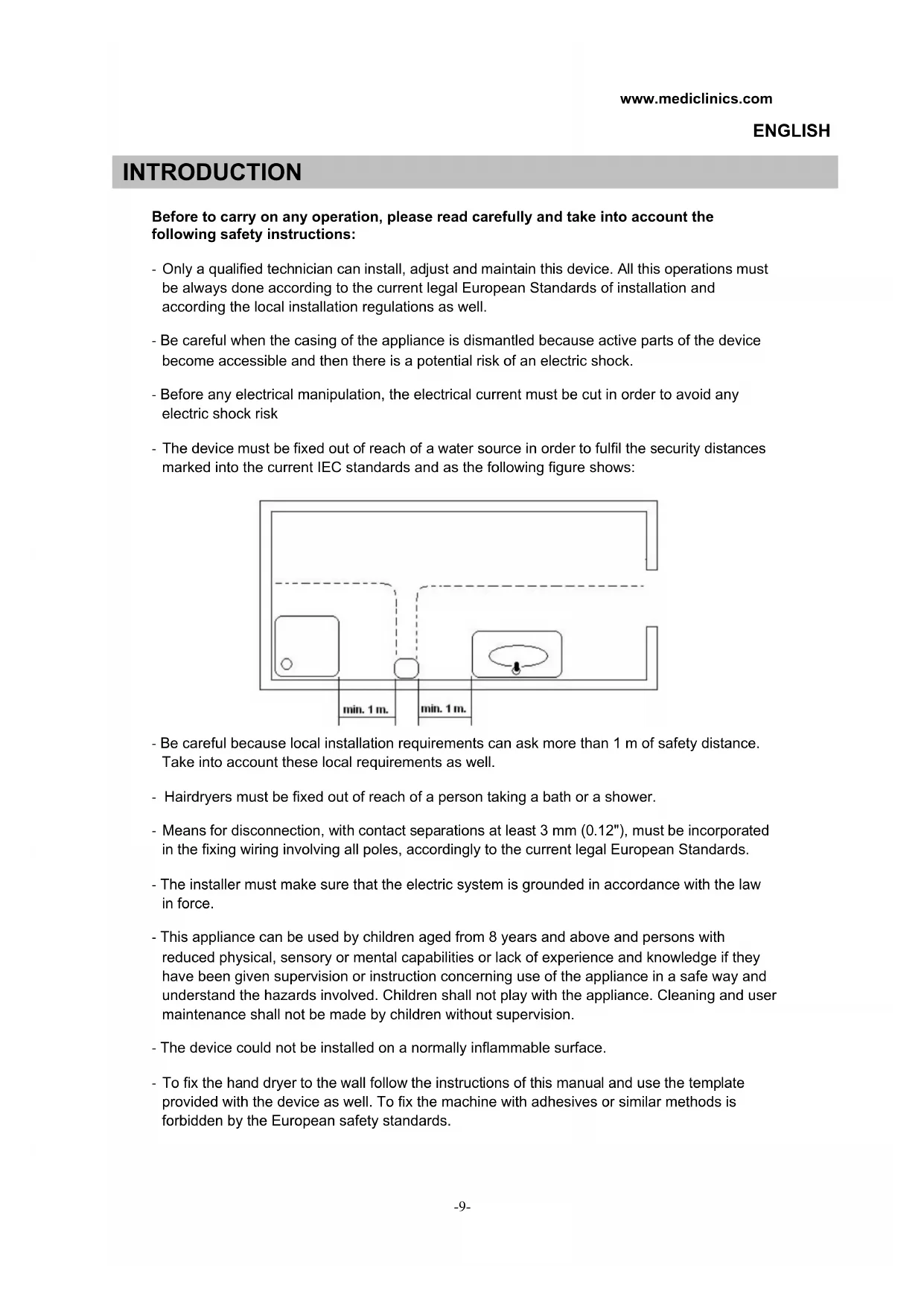
Before to carry on any operation, please read carefully and take into account the following safety instructions: - Only a qualified technician can install, adjust and maintain this device. All this operations must be always done according to the current legal European Standards of installation and according the local installation regulations as well. - Be careful when the casing of the appliance is dismantled because active parts of the device become accessible and then there is a potential risk of an electric shock. - Before any electrical manipulation, the electrical current must be cut in order to avoid any electric shock risk - The device must be fixed out of reach of a water source in order to fulfil the security distances marked into the current IEC standards and as the following figure shows: - Be careful because local installation requirements can ask more than 1 m of safety distance. Take into account these local requirements as well. - Hairdryers must be fixed out of reach of a person taking a bath or a shower. - Means for disconnection, with contact separations at least 3 mm (0.12"), must be incorporated in the fixing wiring involving all poles, accordingly to the current legal European Standards. - The installer must make sure that the electric system is grounded in accordance with the law in force. - This appliance can be used by children aged from 8 years and above and persons with reduced physical, sensory or mental capabilities or lack of experience and knowledge if they have been given supervision or instruction concerning use of the appliance in a safe way and understand the hazards involved. Children shall not play with the appliance. Cleaning and user maintenance shall not be made by children without supervision. - The device could not be installed on a normally inflammable surface. - To fix the hand dryer to the wall follow the instructions of this manual and use the template provided with the device as well. To fix the machine with adhesives or similar methods is forbidden by the European safety standards. INTRODUCTION
‘Machflow’ range hand dryers offer the following technical features: Automatic operation. Hand detection is based on IR-type movement sensors. They are class I devices, with earthing. They provide a potent beam of air, intense and even. The distance for detecting hands is adjustable. The speed of the air generated by the hand dryer can also be adjusted, to achieve an optimum balance between the drying power and noise level. The hand dryers include an intelligent detection system which eliminates static ‘targets’ (marble, shelves or similar). After detecting a static target, the dryer will disconnect a few seconds later. It includes a vandal-proof system with an automatic stop. Maximum continuous functioning time is 60 seconds. It includes a universal high speed motor that is activated gradually to control the inertia of its ignition torque and thus ensure a longer useful life of the hand dryer. ONLY A QUALIFIED TECHNICIAN CAN INSTALL, ADJUST AND MAINTAIN THIS HAND DRYER.
Removal of the casing. The hand dryer is supplied with the casing fitted to the base without tightening (Figure 1). Carefully remove the casing since it is connected to the base by a tab that joins the two pieces (casing and base) at the rear (Figure 2). Remove the casing keeping it at an angle at all times (Figure 3) until the upper tab is completely withdrawn, taking care to: not damage the internal components, in particular the electronic circuit, not scratch or damage the LED sensor screen, not damage the surface of the casing. ATTENTION: WHEN THE CASING IS DISMANTLED ACTIVE PARTS OF THE DEVICE BECOME ACCESSIBLE.
Assembly Connection to the power grid will be preferably through the rear plug. In order to assemble the hand dryer complete the following steps: Make four drill holes with an 8 mm (0,31”) diameter in the wall, using the provided template (Figure 4). Clean the dust away from the holes and insert the wall plugs. Pass the electrical cables from the power grid through the hole with the 22 mm (0,87”) diameter which is situated above the device’s terminal strip (Figure 5).
Firmly screw the base of the device to the wall (Figure 6), ensuring that the 4 silent- blocks are correctly placed between the base and the wall. Connect the electrical cables to the hand dryer’s terminal strip. Connect the cables corresponding to the two phases (N and L) and to earth in the corresponding sockets of the terminal strip, as indicated by the engraved letters (Figure 7).
When making these connections contemplate means for disconnecting from the power grid with a minimum contact separation of at least 3 mm (0,12”) for all poles. These disconnection means must be incorporated into the fixed installation. The hand dryer must be installed against a solid surface only (wall, partition, or similar). Carefully place the casing on the base of the device. To do so place it over the base with a slight incline from top to bottom, in such a way that the tab in the casing correctly inserts into the corresponding slot in the base (Figures 8 and nº 9). Place the screws for fixing the casing to the base, fixing them tightly using the special spanner provided (Figure 10).
Figure 8. Figure 9. Figure 10.-12- During this process of fitting the casing to the base take care not to damage the electronic circuit that is below the hand dryer’s nozzle (Figure 11). It is also very important to ensure that once mounted and screwed to the base the casing has the plastic protector correctly placed on the lower inverted “U” shaped window (Figure 12).
NOTE: contemplate a minimum distance of 400 mm (15,80”) away from ledges, marble tops or wash basins (Figure 13). Avoid as much as possible the presence of reflecting surfaces within the area of the hand dryer’s IR sensor. Adjust the speed of the motor and the detection distance. The hand dryer has means to adjust manually the distance for detecting hands and the speed of the drying air. These adjustments of the motor speed and detection distance must be made by a qualified technician only. The adjustments can be made by moving the respective cursors of the two linear potentiometers, as shown in figure 14.
The hand dryer starts automatically when the hands are placed near the LEDs detection zone, which is just next to the air outlet. Hand detection and the ensuring starting of the machine is based on emission-reflection-reception of an IR light beam coming from the sensors. The detection distance is between 120 and 150 mm approximately. (4.72 – 5.9”). For good hand drying it is advisable to rinse the hands properly in order to remove totally any remains of soap. In order to start the hand drying process, the hands must be rubbed together at an approximate distance of 600 - 700 mm (2,36 - 2,76") from the air output (see figure 15). The hand dryer will stop within 2 - 3 seconds, once the hands are removed. The detection range can be adjusted by turning the potentiometer as shown in figure 14. The maximum time for which the hand dryer will function continuously is 60 seconds. After this time, the hands must be removed from the hand dryer and placed next to it in the same zone once more in order to start the hand dryer up again. This appliance is not intended for use by persons (including children) with reduced physical, sensory or mental capabilities, or lack of experience and knowledge, unless they have been given supervision or instruction concerning use of the appliance by a person responsible for their safety.
Adequate cleaning of the hand dryer will extend its useful life. It is recommended to remove any dust accumulated inside the hand dryer at least once a year. To clean the hand dryer correctly, take the following steps: Disconnect the hand dryer from the power supply. Remove the two lower screws that fix the casing to the base using the special spanner provided. Remove the casing as instructed in the chapter “Removing the casing” and place it on a cloth, to prevent scratching or rubbing at all times. Clean away the dust and remove any dirt accumulated inside the hand dryer, using a dry cloth or a soft brush. Clean from the air input to inside the motor (upper part of the nozzle) preventing dust or dirt falling inside the turbine-motor assembly. Carefully clean the dust away from around the electronic circuit located inside its box- type housing. Carry out this operation taking maximum care not to damage any component of the electronic circuit. Use a soft cloth to clean the surface of the IR sensor protector screen.
Figure 15.-14- Clean the casing using a damp cloth moistened in a solution of neutral soap and water. After cleaning the entire surface rinse the soap from the casing using another cloth moistened in water and dry using a dry cloth. Close the hand dryer by assembling the casing once more, tightening the screws that fix the casing to the base and connect to the power grid. Start the hand dryer up 2 or 3 times in a row to ensure that all remaining dust is extracted. CLEANING OF CHROMED AND GOLD PLATED COVERS For cleaning purposes only a wet cloth is to be used. Do not use any kind of detergent, acids, lye, abrasives, hydrochloric acid, etc. Take care not to damage or force any component.
Electric shock risk - The installer must make sure that the electric system is grounded in accordance with the law in force. - Make sure that the electric system has a high-sensitivity breaker I n ≤ 0.03 A. - Make sure the machine is disconnected from electric power supply, before performing maintenance operation.www.mediclinics.com
Steel casing painted white 1 RC9224008SMD Stainless steel casing with a polished finish 1 RC9213008SMD Stainless steel casing with a satin finish 1 RC9212008SMD Motor assembly 2 RC9111003SMD Electronic circuit 3 RC9121011SMD
CONFORMITY DECLARATION