Speedflow M06AF - Hand dryer Mediclinics - Free user manual and instructions
Find the device manual for free Speedflow M06AF Mediclinics in PDF.
Frequently Asked Questions - Speedflow M06AF Mediclinics
Download the instructions for your Hand dryer in PDF format for free! Find your manual Speedflow M06AF - Mediclinics and take your electronic device back in hand. On this page are published all the documents necessary for the use of your device. Speedflow M06AF by Mediclinics.
USER MANUAL Speedflow M06AF Mediclinics
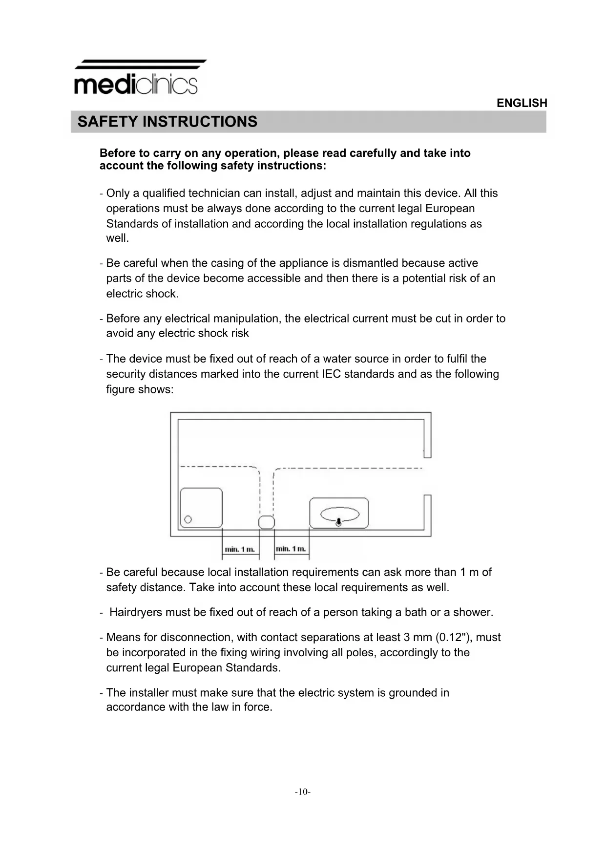
Before to carry on any operation, please read carefully and take into account the following safety instructions: - Only a qualified technician can install, adjust and maintain this device. All this operations must be always done according to the current legal European Standards of installation and according the local installation regulations as well. - Be careful when the casing of the appliance is dismantled because active parts of the device become accessible and then there is a potential risk of an electric shock. - Before any electrical manipulation, the electrical current must be cut in order to avoid any electric shock risk - The device must be fixed out of reach of a water source in order to fulfil the security distances marked into the current IEC standards and as the following figure shows: - Be careful because local installation requirements can ask more than 1 m of safety distance. Take into account these local requirements as well. - Hairdryers must be fixed out of reach of a person taking a bath or a shower. - Means for disconnection, with contact separations at least 3 mm (0.12"), must be incorporated in the fixing wiring involving all poles, accordingly to the current legal European Standards. - The installer must make sure that the electric system is grounded in accordance with the law in force. SAFETY INSTRUCTIONS
- This appliance can be used by children aged from 8 years and above and persons with reduced physical, sensory or mental capabilities or lack of experience and knowledge if they have been given supervision or instruction concerning use of the appliance in a safe way and understand the hazards involved. Children shall not play with the appliance. Cleaning and user maintenance shall not be made by children without supervision. - The device could not be installed on a normally inflammable surface. - To fix the hand dryer to the wall follow the instructions of this manual and use the template provided with the device as well. To fix the machine with adhesives or similar methods is forbidden by the European safety standards.
The Hand dryers Speedflow family has the following technical features: - Automatic operation (IR sensors). - Universal input voltage. Hand dryer works at 100-240 V and 50/60 Hz range. - Adjustable range detection (50-230 mm) - Motor speed adjustable. - Vandal proof operation system (no more than 60 seconds of continuous running). - ADDAG compliance (ADA Accessibility Guideline).
Mains connection and regulations of motor speed and range detection must be handled by an authorized technician. The appliance is supplied with the two lower screws screwed to the base that secures the cover from the inside. The cover should be removed in the following manner:
1. Screw the lower screws in a clockwise direction (CW) with the supplied
special tool until they are fully screwed in place (see figure nº 1).
2. Remove the cover by rasing it a slight angle until the upper securing tab is
freed (see figure nº 2). Remove the cover in a vertical direction without striking the inside of the machine (see figure nº3).
WARNING: when the cover is removed, live parts of the appliance are
exposed. During this operation do not: - Damage any internal components, especially the electronic circuit housed under the volute (see figure nº 4). - Scratch the cover or the visor of the IR sensor.
The appliance's electrical installation is made via rear channelling (figure nº 5), as follows:
1. Drill four Ø 8 mm (Ø 0.31") holes using the
supplied template. Clean up the holes once they have been made. Insert the four plugs until they are flush with the surface (see figure 6).
2. Pass the 3 electric cables (3 cables 16 AWG/105ºC)
from the wall through the entrance hole (Ø 22 mm - Ø 0.87") as figure nº 8 shows. Means for disconnection with contact separations at least 3 mm (0.12") must be incorporated in the fixing wiring. During the installation process, the protection areas should be considered according to Standard VDE 0100.
3. Assure that the four silent blocks of the base-plate are properly
located. Screw in the four supplied screws to firmly secure the base of the appliance to the wall (see figure 7).
4. Connect the Neutral and Line (N, L) wires to the terminal block
and the A/V cable to the earth connection screw (Class I) as figure nº 8 shows.www.mediclinics.com
5. Installing the cover on the hand dryer taking care to insert the
upper tab in its housing in the base-plate (see figure nº 9).
6. Unscrew the screws in a counter-clockwise direction (CCW)
using the supplied special tool (see figure 10).
7. Place the hands inside the detection area of the appliance in
order to assure the right performance of the hand dryer.
Care must be taken during this operation not to touch the electronic circuit that is housed under the volute. NOTE: a minimum distance of 40 cm (15.8") must be allowed between any possible shelves, marble or washbasins (see figure 11). As far as possible, reflecting surfaces should be avoided within the operating range of the IR sensors. MACHINE MUST BE HANDLED ONLY BY AN AUTORIZED TECHNICIAN. The hand-dryer must only be installed on a closed surface, such as a wall, partition or similar.-14-
Speedflow hand dryers family operates by hands detection when it detects their presence. To dry hands correctly we recommend rising well to remove all traces of soap.
If hands are held 60 - 70 mm. (2.36 - 2.76") from the air outlet, the hand dryer will automatically start-up (see figure nº 13). The machine will stop 2 - 3 seconds after use. Range detection can be adjusted turning around the potentiometer as figure nº 12 shows. This hand dryer has a system to avoid vandalism and for this reason the device will completely stop working after 60 seconds operating without interruption. This appliance is not intended for use by persons (including children) with reduced physical, sensory or mental capabilities, or lack of experience and knowledge, unless they have been given supervision or instruction concerning use of the appliance by a person responsible for their safety. CHILDREN SHOULD BE SUPERVISED TO ENSURE THAT THEY DO NOT PLAY WITH THE HAND DRYER.
Correct cleaning of the machine will lengthen its working life considerably. When in use, the machine will accumulate dust inside wich should be cleaned out if used regularly, at least once a year.
1. Remove the mains supply to the hand-dryer.
2. Remove the cover (see the section "INSTALLATION" in this manual).
3. Clean away any accumulated dust on the scroll-fun with a soft-bristle brush
while rotating it manually.
4. Use the same brush to clean away all accumulated dust from the other
5. Use a medium brush to clean the air inlet grill. Check the motor brushes
condition. These should be replaced when they are less than 5 mm (0.2").
6. Carefully remove any dust from the electronic circuit using a fine brush.
Check that there is no dust or other dirt on the hand-detection sensors.
7. Ensure that the IR LED visor is totally clean.
8. Start up the machine and leave until no further dust remaining from the
cleaning process, comes out from the air outlet.
CLEANING OF THE COVERS
For cleaning purposes only a wet cloth is to be used. Do not use any kind of detergent, acids, lye, abrasives, hydrochloric acid, etc. Take care not to damage or force any component. NOTE: All maintenance and cleaning processes must be carried out by qualified personnel.
MOUNTING INSTRUCTIONS
To mount onto wall, be sure there are no hidden electrical circuits or pipes in the mounting location.
Place the mounting template (provided) on the wall to mark location of four mounting screw holes.
Drill four holes (Fig.1) Ø8 (5/16”) diameter and 45mm (1 ¾”) depth.
Take off the residual dust from the holes.
Insert nylon plugs (provided) into four holes (Fig.2-3).
Place base plate on wall (Fig.4).
Fix the base plate firmly on the wall (Fig.5-6).
MOUNTING ITEMS PROVIDED.