
ELFAMATIC uC 3000 - Heating AEG - Free user manual and instructions
Find the device manual for free ELFAMATIC uC 3000 AEG in PDF.
| Product type | Heat accumulation control |
| Brand | AEG |
| Model | ELFAMATIC uC 3000 |
| Nominal voltage | 200-230 V +10%/-15%, 50/60 Hz |
| Power consumption | 3,0 VA |
| Fuse | T 1,6 L 250 V |
| Protection | IP 20 (after mounting), Protection class II |
| Permissible ambient temperature | 0 °C to +50 °C |
| Max load Z1/Z2 | 300 W |
| Switching capacity SH | 100 VA (cos φ 0,5) |
| Display | Backlit LCD screen |
| Climate sensor | DIN type, IP 54, Class II, -40 °C to +50 °C, Ø 11,5 x 35 mm |
| Sensor cable | 2 x 0,75 mm², length 1.4 m (max. 30 m with shielded cable) |
| Mounting | On DIN rail in distribution board |
| Main functions | Automatic synchronization, forward/reverse/expansion control, time programming, summer logic |
| Special settings | E1, E2, L50, E3, TEP, T5P, FB, L7, etc. |
| Maintenance | No special maintenance required |
| Warranty | According to country of purchase, by qualified installer |
| Environment | Recycle packaging according to local regulations |
Frequently Asked Questions - ELFAMATIC uC 3000 AEG
User questions about ELFAMATIC uC 3000 AEG
0 question about this device. Answer the ones you know or ask your own.
Ask a new question about this device
Download the instructions for your Heating in PDF format for free! Find your manual ELFAMATIC uC 3000 - AEG and take your electronic device back in hand. On this page are published all the documents necessary for the use of your device. ELFAMATIC uC 3000 by AEG.
USER MANUAL ELFAMATIC uC 3000 AEG
Operating and Installation instructions
ELFAMATIC C 3000
Régulation de charge
Connection diagram 3
Brief instructions 21
Setting time 21
Setting charging model 21
- Operating instructions 22
1.1 Description of device 22
1.2 Operation 23
1.3 Troubleshooting 23
1.4 Putting into operation 23
1.5 Test function 28
1.6 Controller self-test 29
2.Installation instructions 30
2.1 Regulations and specifications 30
2.2 Technical specifications 30
2.3 Installation 30
2.3.1 Controller 30
2.3.2 Electrical connection 31
3.Guarantee 34
3.1 Environment and recycling 34
Nederlandss
Inhoudsoverzicht
Brief instructions - for rapid programming
If all of the following requirements are met, the device can be put into operation in the way described below.
Storage heater system with control voltage system 80% ED
- Use of the supplied or an existing DIN atmospheric sensor
- Charging model is provided in the table on page 8-10.
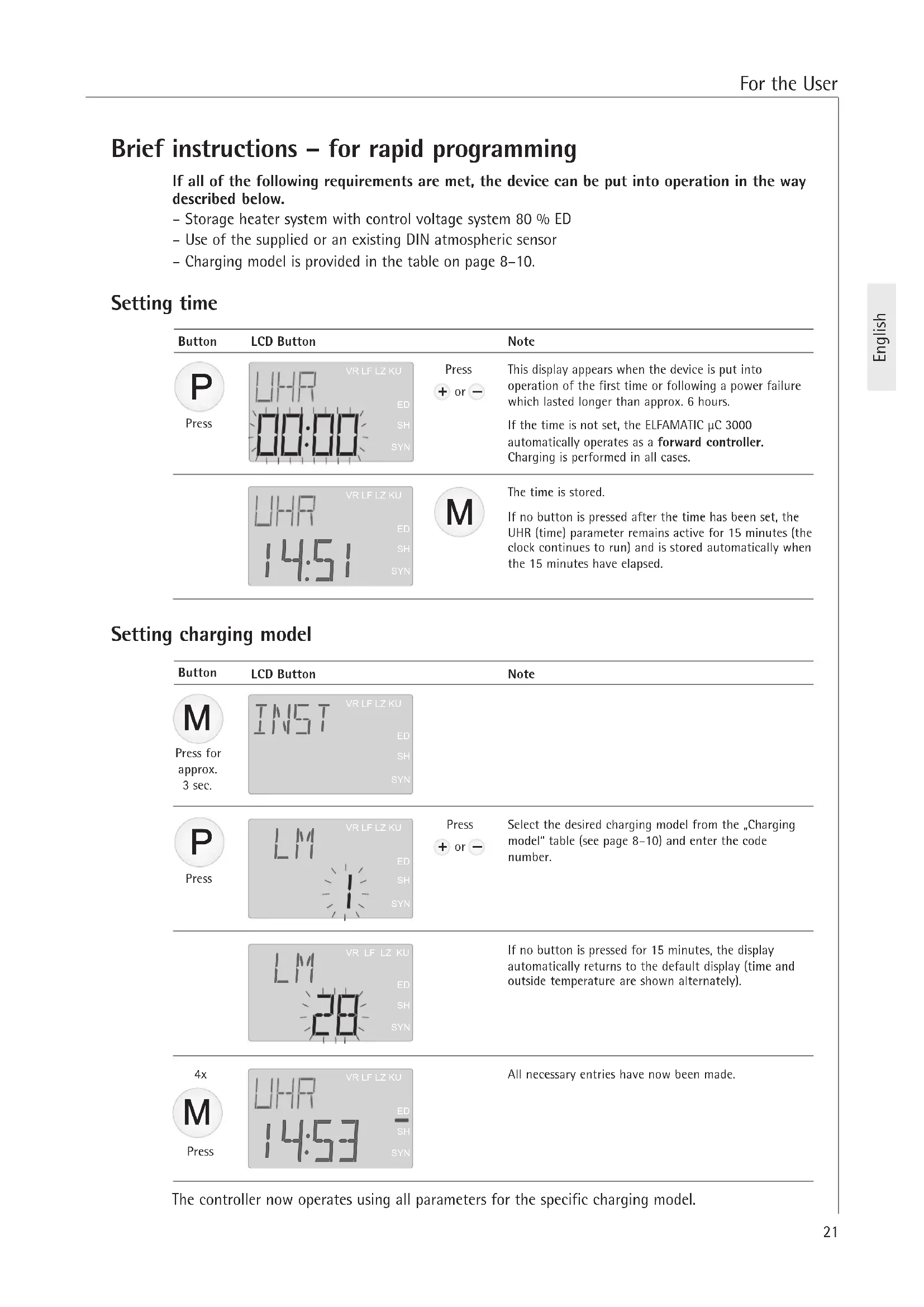
Setting time
| Button | LCD Button | Note | |
| Press | VR LF LZ KU UHR ED SH SYN | Press + or - | This display appears when the device is put into operation of the first time or following a power failure which lasted longer than approx. 6 hours. If the time is not set, the ELFAMATIC μC 3000 automatically operates as a forward controller. Charging is performed in all cases. |
| VR LF LZ KU UHR ED SH SYN | M | The time is stored. If no button is pressed after the time has been set, the UHR (time) parameter remains active for 15 minutes (the clock continues to run) and is stored automatically when the 15 minutes have elapsed. |
Setting charging model
| Button | LCD Button | Note |
| M Press for approx. 3 sec. | INST VR LF LZ KU ED SH SYN | |
| P Press | LM VR LF LZ KU ED SH SYN | Press + or - Select the desired charging model from the „Charging model" table (see page 8-10) and enter the code number. |
| LM VR LF LZ KU ED SH SYN | If no button is pressed for 15 minutes, the display automatically returns to the default display (time and outside temperature are shown alternately). | |
| 4x M Press | UHR 14:53 VR LF LZ KU ED SH SYN | All necessary entries have now been made. |
The controller now operates using all parameters for the specific charging model.
1. Operating instructions
1.1 Description of device
The charging controller ELFAMATIC C3000 continuously calculates the correct amount of thermal energy stored in the storage heater.
The outside temperature trend and the tariff information from the power supply company are taken into consideration.
The ELFAMATIC C3000 has a backlit LCD.
In normal operating mode, the time (or the operating time if autosynchronisation is deactivated), the temperature measured by the outside temperature sensor and all operating states (by pressing the individual buttons) are displayed on the LCD.
In normal operating mode, the backlight is switched off but is switched on again as soon as one of the buttons M, P, + or - is pressed. It switches off again after 10 seconds if no button is pressed.
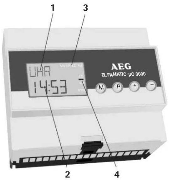
LCD:
1 Active parameter
2 Current parameter value
3 Status display VR / LF / LZ / KU
4 Status display ED / SH / SYN
Buttons:
M Select menu
P Select parameter
+ Change parameter
1.2 Operation
The time and the level of storage heater charging can be changed or set during normal operation.
Changing/setting time . . .
| Button | LCD | Button | Button | Note |
| Press | VRLFLZKU URHR ED SH SYN | Press + or - | P Press twice | Holding down the button activates rapid setting mode. If no button is pressed for 15 minutes, the set time is adopted automatically and the backlight switches off. |
| Button | LCD | Button | Button | Note |
| Press twice | +/- - VR LEL ZKU ED SH SYN | Press + or - | Press | In this menu, the basic charging mode of all storage heaters connected to the ELFAMATIC μC 3000 can be changed by +/-4 °C according to requirement. 1 °C corresponds to approx. 3.5 % more/less charging (max. +/-15%). The charging rate should be changed in small steps only (0.5-1 °C) as any change does not become noticeable until the following day. |
Power failure
The clock has a power reserve of approx. 6 hours in the event of a power failure. The set parameters (e.g. charging model) are stored permanently.
If the power failure lasts longer than approx. 6 hours, the clock will be set to 00:00 again and flash until the time is changed (see above).
Summer/winter time
Deviations of approx. 1 hour between the displayed time and the actual time have no effect on the functions of the ELFAMATIC C 3000.
1.3 Troubleshooting . . .
"FU" (open circuit in sensor) or "FS" (short-circuit in sensor) and the time are displayed alternately.
The atmospheric sensor and/or the selected setting for the atmospheric sensor must be checked by a specialist technician.
1.4 Putting into operation
1. Basic settings
The charging model and atmospheric sensor are specified in the respective list.
Changes to the individual parameters are adopted immediately after they are entered. If no button is pressed for 15 minutes after a change has been made (irrespective of which parameter has been changed), the display automatically returns to the default display (time and outside temperature are shown alternately).
| Button | LCD Button | Note | |
| Press | URLF LZKU 09:16 SYN | Press + or - | If the time is not set, the ELFAMATIC μC 3000 automatically operates as a forward controller. Charging is performed in all cases. If the time is adjusted, the controller operates in forward control mode until the next main release in order to ensure correct autosynchronisation. |
| Press for pprox. 3 sec. | INST VR LF LZ KU ED SH SYN | ||
| Press | LM VR LF LZ KU ED SH SYN | Press + or - | Charging model - Select the desired charging model from the „Charging model list" (page 8-10) and enter the code number. |
| Press | EIS VR LF LZ KU ED SH SYN | Press + or - | ED system - Entry of the ED system for the storage heater system (30-100%) or „EL" for electronic charging controllers. With ex-works AEG storage heaters, the factory-set ED system of 80% is correct. |
| Press | WF UR LF LZ KU ED SH SYN | Press + or - | Atmospheric sensor - Select the desired atmospheric sensor from the „Atmospheric sensor list" (see below) and the sensor code. If the atmospheric sensor installed in the storage heater system is not in the atmospheric sensor list, the supplied DIN atmospheric sensor should be used (sensor code „1"). |
| Press 4 times | UHR UR LF LZ KU ED SH SYN | All controller parameters have now been set. The E1 value (SONG) menu) may have to be adapted depending on the normal outside temperature value, and the E2 value may have to be adapted depending on the type of building (see page 25). | |
Atmospheric sensor list
| Sensor code Resistance (ohm) at temperature20 °C 10 °C 0 °C -10 °C -15 °C | ||||||
| Standard sensor to DIN (AEG) 1 2432 3657 5641 8945 11390 | ||||||
| Schlüter, AEG (old sensor, W1-W4 with adapter) | 2 | 2000 | 3255 | 5490 | 9633 | 12970 |
| ACEC | 3 | 2200 | 3295 | 5000 | 7695 | 9600 |
| AEG (connect W1/W4 only) | 4 | 1800 | 2867 | 4600 | 7443 | 9500 |
| Frensch, Gräßlin, ACEC | 5 | 2000 | 2991 | 4608 | 7335 | 9380 |
| MALAG | 6 1800 | 3138 | 5400 | 9210 | 12000 | |
| Siemens | 7 1983 | 3147 | 5202 | 9641 | 14000 | |
| Siemens 2 | 8 | 2000 | 3166 | 5100 | 8370 | 10800 |
| Witte (4-core), AEG (W1/W4) | 9 | 1800 | 2867 | 4600 | 7443 | 9500 |
| EM 3 or EMZ . . . (old Stiebel Eltron controller) | 10 | 1128 | 1367 | 1619 | 1863 | 1976 |
2. Special settings
Charging model is not in list or certain parameters must be changed
Changes to the individual parameters are adopted immediately after they are entered. If no button is pressed for 15 minutes after a change has been made (irrespective of which parameter has been changed), the display automatically returns to the default display (time and outside temperature are shown alternately).
Operating principle
The following points are important in understanding the operating principle of the ELFAMATIC C 3000:
-
The temperature used to calculate the output signal is not the instantaneously measured outside temperature but an average value derived from the determined instantaneous values with a trend component.
-
During standard operation, the ELFAMATIC C 3000 functions in autosynchronisation mode, i.e. the timing element is synchronised with the main release automatically while taking the current time into consideration. As a result, it is no longer necessary to set the number of hours since release start (operating time). When put into operation for the first time, the controller operates in forward control mode until it receives the first LF main release pulse; this ensures that charging is performed if an additional release is given during this time.
-
With charging models where a permanent release is given, e.g. at the weekend (Powertherm), the ELFAMATIC C3000 uses the previous release times to determine the start times for main release and additional release. If the ELFAMATIC C3000 is put into operation on a Friday (so that it is not possible to store the release times), synchronisation could take until Monday evening. During this time, the controller operates in forward control mode in order to ensure that charging is performed.
Factory settings:
Charging model 1
E1=-14°C
E2=18°C
E3=7h
TEP = 20%
LSO = 15%
[ \mathrm{TSP} = 85\% ]
Interaction of the adjusters
with the ELFAMATIC C3000
| Button | LCD Button | Note |
| M for approx. 3 sec. | INST VRLFZKU ED SH SYN | INSTALLation menu - After this menu is activated, the parameters "EDS" and "LF" must be set as described under "Basic settings" on page 23. The parameter "LF" can remain set to the displayed value. (Press the M button after entering the value) |
| M | SONO VRLFZKU ED SH SYN | SONO (special settings) |
| P | E1 14°C SYN | + or - Full charging - Outside temperature (calculated using the following formula) at which the storage heater is to be fully charged. Setting range: -25 to 11 °C E1 = ∅R - tF tF + tZF (∅R - va) ∂R=Nominal room temperature ∂a= Normal outside temperature to DIN 4701 tF = Release length tZF = Additional-release length |
| P | EZ 18°C SYN | + or - Charging start - Outside temperature at which charging of the storage heater is to begin (value must be at least 6 °C above the E1 value). Factory setting 18 °C |
| P | L50 VRLFZKU ED 15% SH SYN | + or - Summer logic - If E2 is underranged, the storage heater is charged to at least this value. Setting range: 0 to 30 % |
| P | E3 ED SH SYN | + or - Reduction time - Depends on the control type. Setting range: 0 to 12 h Forward control E3 = 0 Spread control E3 = Main release hours / 2 (e.g. 8h/2 = 4h) Backward control E3 = Main release hours - 1 h (e.g. 8h-1 = 7h) |
| P | TEP VRLFZKU ED 20% SH SYN | + or - Charge minimum - End point of day-time characteristic in % of the day-time start value, corresponds to the remaining charge that the storage heater has at the end of the day-time characteristic. Setting range: 0 to 60 % |
| P | T5P VRLFZKU ED 20% SH SYN | + or - Day-time start value in % of the nominal charging level. This can be used to reduce day-time recharging. Setting range: 0 to 100 % |
| P | FB VRLFZKU ED 20% SH SYN | + or - Charge reduction in % of the nominal charging level with activation of terminal KU, e.g. for holiday mode: reduced charging during absence. Setting range: 0 to 100 % |
| P | L7 VRLFZKU ED 22h SYN | + or - Cycle time of timing element - usually 22h. Depends on charging model of power supply company. |
| P | VR LFLZ KU E0 SH SYN | + or - Locking in hours after LT release. Switchover of timing element voltage from LF to L. |
| P | VR LFLZ KU E0 SH SYN | + or - Point of switchover from night-time to day-time characteristic. Setting range: 6 to 20 h |
| P | ST: R E0 SH SYN | + or - Control type: R = Backward control S = Spread control V1 = Forward control with variable day-time characteristic M1 = Neckarwerke (name of a company) V = Forward control |
| P | VR LFLZ KU E0 SH SYN | + or - Day-time forward control JR: Activation of terminal VR causes suppression of day-time characteristic. MEIN: Terminal VR not active after switchover to day-time characteristic (N/D). |
| P | STL: R E0 SH SYN | + or - Day-time control signal suppression - If "E1 S = JA (Yes)" and no additional release is given (outside temperature > E1 S). |
| P | STL: R E0 SH SYN | + or - Control signal suppression AT>E2 - if the outside temperature is higher than the E2 value. |
| P | E1:5 E0 SH SYN | + or - With this setting, day-time recharging can be prevented if the outside temperature is higher than the value set for E1 S. If "JR" (Yes) is set here, the E1 S value can be entered next; if "MEIN" (No) is set, the display moves to the next parameter. |
| P | VR LFLZ KU E0 SH SYN | + or - Set the desired outside temperature as of which day-time recharging is to be prevented. |
| P | VR LFLZ KU E0 SH SYN | + or - Main release hours |
| P | VR LFLZ KU E0 SH SYN | + or - Additional-release hours |
| P | 5YNC VRLFELZ KU RS = Autosynchronisation. The controller synchronises automatically with the charging release if the main release comes later than defined in the parameter "S LF". PO = Powertherm charging system. The controller synchronises automatically with the charging release and, with continuously applied LF, internally simulates interruption of the charging release at the 24 hours previously determined time points for 48 hours. LF = Synchronisation with the charging release. The controller synchronises with the charging release signal. If "LF" is selected, the number of hours which have passed since the charging release must be set in the user menu instead of the time (during normal operation, the display changes from UHR/AF to LA/AF). | |
| P | 5LF VBLFELZ KU ED SH SYN | + or - Time of earliest possible main release. Caution: If in the case of certain charging models from the power supply companies an additional release is given very late, the parameter "S LF" must be set to a time after the additional release, e.g.: additional release from 21:00 to 23:00 - Set "S LF" to at least 22. |
| P | SAVE VBLFELZ KU ED SH SYN | + or - The set parameters can be stored so that they can be called up again after temporary parameter changes. The set parameters are stored by holding down the + button for longer than 3 seconds. If required, the parameters stored in this way can be called up again by holding down the - button for longer than 3 seconds. |
| M 3x | UHR VBLFELZ KU ED SH SYN | |
| Factory setting: | A reset to the factory setting is made by pressing the - and + keys in the INST menu simultaneously for more than 3 seconds. | |
1.5 Test function
The storage heater can be checked in the TEST menu.
| Button | LCD Button | Note | |
| M for approx. 3 sec. | INST VRL FL Z KU ED SH SYN | ||
| M 2x | TEST VRL FL Z KU ED SH SYN | TEST menu | |
| P 3x | LOT VHL FL Z KU ED RUS SH SYN | + or - | Parameters for testing the control line and the charging controllers in the storage heaters. RUS = Function disabled 0 % = Control signal for charging suppression is output 100 % = Control signal for full charging is output |
| Button | LCD Button | Note |
| P | RF M VRL LF L2 KU ED SH SYN | + or - Display of the average outside temperature used for calculating the charge. The currently measured outside temperature value is entered in the memory by holding down the + and - buttons simultaneously for longer than 3 seconds. |
| Only for Powertherm charging model | P | Stored main release time |
| P | LZ VRL LF L2 KU ED SH SYN Stored additional-release time | |
| M | UHR VRL LF L2 KU ED SH SYN |
1.6 Controller self-test
The ELFAMATIC C3000 must be de-energised before the self-test can be started. Then press the + and - buttons simultaneously and switch the power supply back on at the same time.
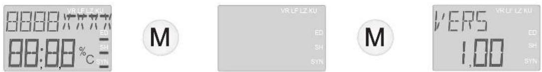
Display segment test Software version
| Button | LCD Button | Bemerkung |
| M | EEP VLELFZKU ED SH SYN | EEProm memory version |
| M | TAST VLELFZKU ED SH SYN | P Button test - An internal device test is performed to check that the buttons are functioning correctly. Press the P button. The buttons + , - and M were already pressed during the self-test and therefore do not need to be tested again. |
| E/A VLELFZKU ED SH SYN | + or - Output test - The relay and Triac can be activated alternately by pressing the buttons + and - . | |
| M | TEMP VLELFZKU ED SH SYN Outside temperature | M 2x End - If no button is pressed for 2 seconds, the display returns to the standard mode. |
2. Installation instructions
2.1 Regulations and specifications
- Installation and electrical connection must be performed by a specialist technician in compliance with these installation instructions.
- All electrical connection and installation work must be performed in accordance with the VDE regulations (0100), specifications from the responsible power supply company and the relevant national and regional regulations.
- See the information and materials enclosed in the device packaging.
- Observe the information on the device rating plate. The specified voltage must be identical to the mains voltage.
2.2 Technical specifications
| Nominal voltage 200-230 V +10 % / -15 % AC 50/60 Hz | |
| Power consumption 3.0 VA | |
| ED system Setting range 30 to 100 %, or "EL" | |
| Max. load Z1/Z2 - 300 W | |
| Switching capacity SH 100 VA / cos φ 0,5 | |
| Fuse T 1.6 L 250 V | |
| Ambient temperature range 0 °C to +50 °C | |
| Degree of protection IP 20 (after installation) | |
| Safety class II (total insulation) | |
DIN atmospheric sensor:
| Resistance values See page 24 | |
| Degree of protection IP 54 | |
| Safety class II | |
| Ambient temperature range -40 °C to +50 °C | |
| Connecting cable 2 x 0.75 mm | 2, approx. 1.4 m long (cable length between sensor and ELFAMATIC μC 3000: max. 30 m - shielded cables required for longer lengths) |
| Dimensions | Ø 11,5 x 35 mm |
2.3 Installation
2.3.1 Controller
The ELFAMATIC C 3000 must be fitted in the bottom row of a distribution board, whereby a gap of one SI circuit-breaker width must be provided at the sides. Shock protection to safety class II is provided if the ELFAMATIC C 3000 is installed in
- a small distribution board to DIN or
- a distribution board to DIN
The ELFAMATIC C3000 consists of a base with terminals for rail mounting as well as the plug-in housing with the electronic components.
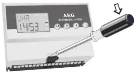
The top part of the housing is removed from the base by releasing the lower housing catch using a screwdriver and then pulling off the top part.
The base must be de-energised before the top part of the housing is mounted.

Replacing an existing ELFAMATIC C 2100
The device must be connected as shown in the circuit diagram.
Removal
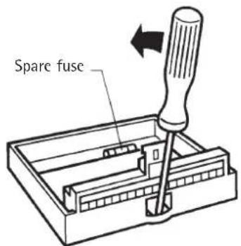
To remove the controller, release the top part from the base (as described above) and disconnect the connecting cables.
Then release the base from the rail as shown in the illustration below.
Sensor
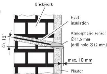
Normally, the installation location of the atmospheric sensor should be selected according to the following criteria:
- Installation according to the illustration below
Min. height above ground: 2.5m - The sensor should be mounted on the side of the building on which the main rooms to be heated are located (avoid mounting on the north side of the building where possible)
- The sensor must be mounted at a sufficient distance from doors, windows, exhaust-air ducts, etc.

The cable between the sensor and control unit must be suitable for mains voltage.
2.3.2 Electrical connection
The terminal assignment is given in the table below.
Preliminary check
Insulation test on all cables (without consumers)
- Resistance test (turn the rotary knob of charging controller on each heater clockwise as far as it will go)
- At Z1 and Z2 of the ELFAMATIC C 3000:
R=176Ω...100kΩ
The measured resistance must not be less than 176 Ω.
- At W1 and W2 of the ELFAMATIC C 3000:
Atmospheric sensor
R = See table in page 24
Make sure that the correct sensor code is entered.
- Switch on the mains voltage and measure between L and N.
- Simulate the LF release and measure the voltage between LF and N.
- Switch off the mains voltage.
Attach the top part of the housing to the base.
Sensor installation
Normal brickwork or brickwork with inner insulation: Sensor body fitted flush with plaster surface or projecting max. 10mm above plaster surface.
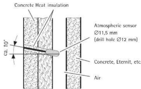
Non-bearing and rear-ventilated facade: Half of sensor body fitted in air duct.
| Terminal Explanation | |
| W1/W2 | DIN atmospheric sensor or atmospheric sensor specified in atmospheric sensor list on page 24. |
| LF Power supply company control, main release The controlled outer conductor LF of the power supply company is connected to this terminal - it is used to start the timing element (not applicable if NW [Neckarwerke] is set for the parameter „ST". | |
| LZ Power supply company control, additional release Only used if the power supply company provides a second controlled outer conductor in the day-time charging time, otherwise this terminal remains unused. | |
| VR/LL Forward/backward switchover: Operating time control if NW (Neckarwerke) is set for the parameter „ST". | |
| KU | Characteristic switchover (reduction by the value set for the parameter „Rb"). |
| Z1 Z1 = Clocked control line (L) Z2 Z2 = Unclocked control line, connected to N; single-wire control possible. The mains-voltage clock signal is applied at these terminals. Terminal Z2 is internally connected to terminal N. The clocked outer conductor is applied as a control signal to terminal Z1. | |
| L Mains voltage 200 - 230 V +10 % -15 %, AC 50 Hz. N When connecting the device, make sure that the outer conductor is connected to terminal L. | |
| SH SH = Charging contactor (see connection diagram on page 3 for SH). | |
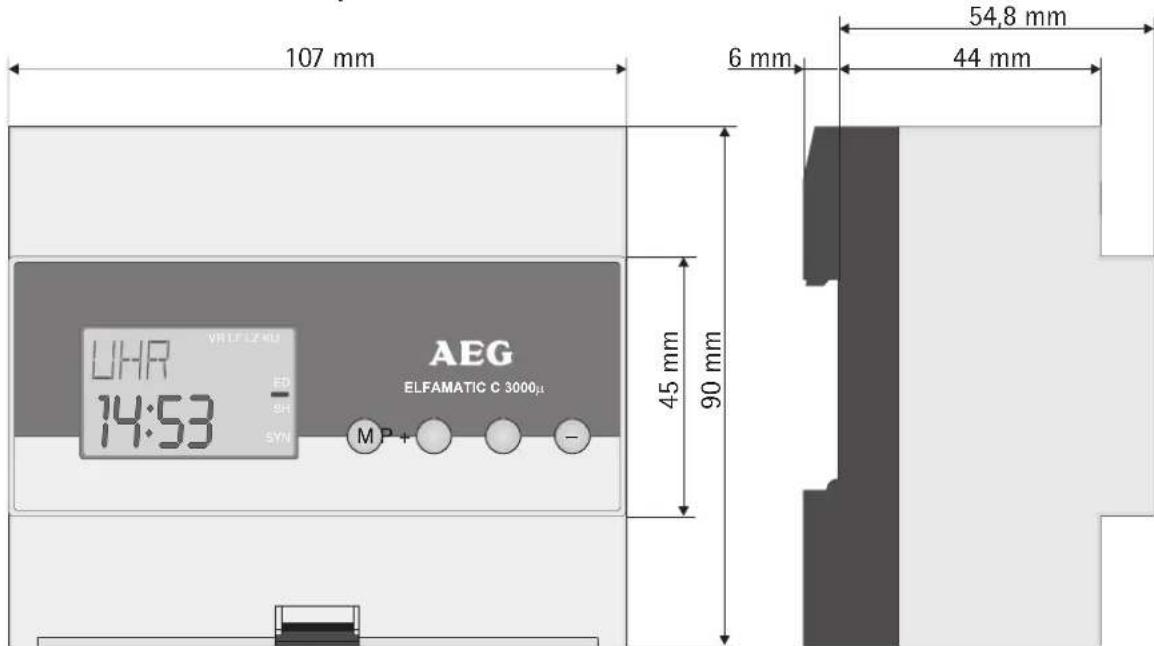
Dimensions of ELFAMATIC C 3000
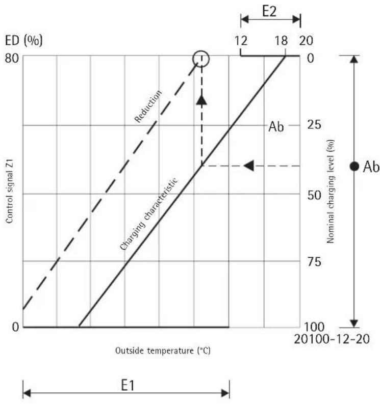
Reduction of charging by activating terminal KU
3. Guarantee
For guarantee please refer to the respective terms and conditions of supply for your country.

The installation, electrical connection and first operation of this appliance should be carried out by a qualified installer.
The company does not accept liability for failure of any goods supplied which are not installed in accordance with the manufacturer's instructions.
3.1 Environment and recycling
Please help us to protect the environment by disposing of the packaging in accordance with the national regulations for waste processing.


- ELFAMATIC C 3000
- Régulation de charge
- Nederlandss
- Inhoudsoverzicht
- Brief instructions - for rapid programming
- Setting time
- Setting charging model
- Operating instructions
- Description of device
- LCD:
- Buttons:
- Operation
- Power failure
- Summer/winter time
- Troubleshooting . . .
- Putting into operation
- Basic settings
- Special settings
- Operating principle
- Test function
- Controller self-test
- Installation instructions
- Regulations and specifications
- Technical specifications
- Installation
- Controller
- Replacing an existing ELFAMATIC C 2100
- Removal
- Sensor
- Electrical connection
- Preliminary check
- Guarantee
- Environment and recycling
Brand : AEG
Model : ELFAMATIC uC 3000
Category : Heating