
WSP 600 HF - Heating AEG - Free user manual and instructions
Find the device manual for free WSP 600 HF AEG in PDF.
| Product Type | Electric heat accumulator, fireplace model |
| Brand | AEG |
| Model | WSP 600 HF |
| Storage capacity | 48 kWh |
| Nominal charge | 6.0 kW |
| Supply voltage | 3/N/PE ~ 400 V |
| Additional heating element | 1.0 kW |
| Dimensions (H x W x D) | 1056 x 670 x 350 mm |
| Weight | Approx. 330 kg |
| Refractory bricks | 3 x SP26, 6 x SP27 |
| Operation | Automatic heat storage during off-peak hours, release via fan controlled by room thermostat |
| Regulation | Automatic or manual charge regulation, integrated or external room thermostat |
| Summer use | Set buttons to MIN, do not switch off the regulation power supply |
| Maintenance | Low maintenance; self-lubricating fan; dust cleaning by qualified installer; safety component check after 10 years |
| Safety | Surface temperature may exceed 80°C; do not place flammable objects; minimum distances: 10 cm from sides and top, 25 cm from air outlet grille |
| Installation | Wall fixing mandatory to prevent tipping; floor must support weight; electrical connection by certified electrician |
| Spare parts | Available on request with appliance type and serial number |
| Warranty | Valid in country of purchase; assembly and first commissioning by qualified installer |
Frequently Asked Questions - WSP 600 HF AEG
User questions about WSP 600 HF AEG
0 question about this device. Answer the ones you know or ask your own.
Ask a new question about this device
Download the instructions for your Heating in PDF format for free! Find your manual WSP 600 HF - AEG and take your electronic device back in hand. On this page are published all the documents necessary for the use of your device. WSP 600 HF by AEG.
USER MANUAL WSP 600 HF AEG
Electric Storage Heaters
High Line Storage Heater
Operating and Installation instructions
WSP 600 HF
Français
- Operating Instructions 18
1.1 Technical Description 18
1.2 Operation 18
1.2.1 Heat Storage 18
1.2.2 Heat Discharge 18
1.2.3 Summer Operation 18
1.2.4 Energy saving tips 19
1.3 Important Instructions 19
1.4 Care and Maintenance 20
1.5 Important note 20
1.5.1 General 20
1.5.2 Defects 20
1.6Trouble Shooting Tips 21
2.Installation instructions 22
2.1 Technical Data 22
2.2 Heater Positioning and Installation 22
2.2.1 Procedures to be followed 22
2.2.2 Choosing the Heater Position 22
2.2.3 Minimum Clearances 23
2.2.4 Tilting Safety, Wall Mounting 23
2.2.5 Heater Dimensions 23
2.3 Assembly and Electrical Connection 24
2.3.1 Heater Assembly 24
2.3.2 Element Ratings 26
2.3.3 Disassembly of Fan Drawer 26
2.3.4 Electrical Connection 27
2.3.5 Cable Feed 27
2.3.6 Circuit Diagram WSP 600 HF 28
2.4 Rating Label 29
2.5 Spare Parts 29
2.6 Accessories 30
2.6.1 Charge Control 30
2.6.2 Room Thermostat 30
2.6.3 Thermal Switching Relay 30
2.6.4 Day-acting Element 30
2.6.5 Further Accessories 30
2.7 Commissioning the Heater 31
2.8 Re-assembly 31
3.Guarantee 31
3.1 Environment and recycling 31
François
Contenu
1. Operating Instructions
1.1 Technical Description
Storage heaters store electrically generated heat during low-cost electricity tariff periods (depending on the electricity supply company, mainly during the night hours). This is then discharged according to the desired room temperature as hot air by a fan and to a small extent through the surface of the heater.
1.2 Operation
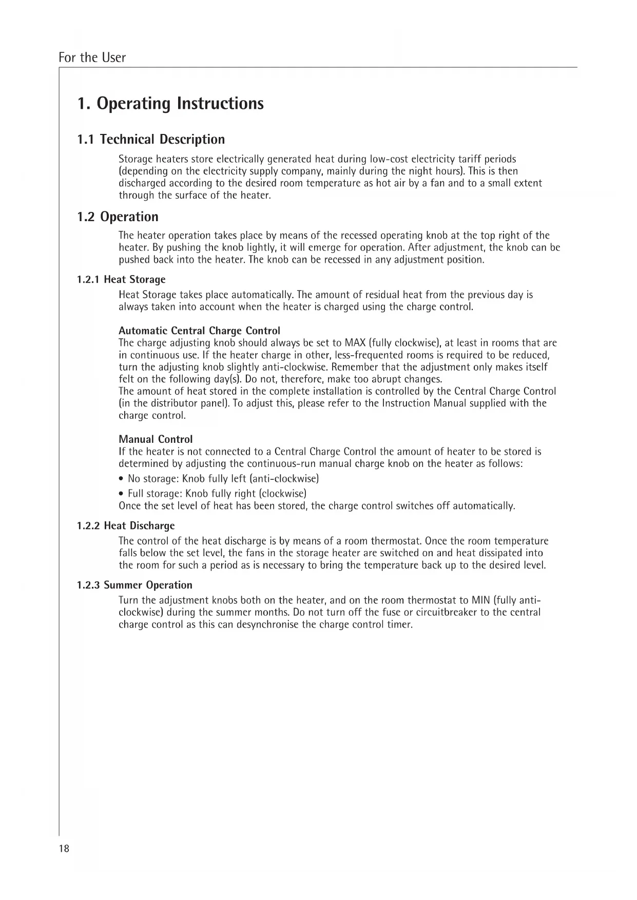
The heater operation takes place by means of the recessed operating knob at the top right of the heater. By pushing the knob lightly, it will emerge for operation. After adjustment, the knob can be pushed back into the heater. The knob can be recessed in any adjustment position.
1.2.1 Heat Storage
Heat Storage takes place automatically. The amount of residual heat from the previous day is always taken into account when the heater is charged using the charge control.
Automatic Central Charge Control
The charge adjusting knob should always be set to MAX (fully clockwise), at least in rooms that are in continuous use. If the heater charge in other, less-frequented rooms is required to be reduced, turn the adjusting knob slightly anti-clockwise. Remember that the adjustment only makes itself felt on the following day(s). Do not, therefore, make too abrupt changes.
The amount of heat stored in the complete installation is controlled by the Central Charge Control (in the distributor panel). To adjust this, please refer to the Instruction Manual supplied with the charge control.
Manual Control
If the heater is not connected to a Central Charge Control the amount of heater to be stored is determined by adjusting the continuous-run manual charge knob on the heater as follows:
- No storage: Knob fully left (anti-clockwise)
Full storage: Knob fully right (clockwise)
Once the set level of heat has been stored, the charge control switches off automatically.
1.2.2 Heat Discharge
The control of the heat discharge is by means of a room thermostat. Once the room temperature falls below the set level, the fans in the storage heater are switched on and heat dissipated into the room for such a period as is necessary to bring the temperature back up to the desired level.
1.2.3 Summer Operation
Turn the adjustment knobs both on the heater, and on the room thermostat to MIN (fully anticlockwise) during the summer months. Do not turn off the fuse or circuitbreaker to the central charge control as this can desynchronize the charge control timer.
1.2.4 Energy saving tips
- Only heat when necessary.
- Keep the room temperature at 20^ if possible. Each degree above 20^ increases the heating costs by 6 to 7% . Likewise, each degree below 20^ saves the same amount of energy.
- Do not heat only by the radiation from the surfaces of the heater, but use the fan as well. If necessary, turn the heater charge adjusting knob slightly down (anti-clockwise).
- Use an automatic charge control to charge the heater if possible. Then, the heater will only store the amount of heat necessary to cover the heat load for the following day. A correctly adjusted charge control is a prerequisite for an economic operation of the storage heater at comfortable room temperatures.
- During long periods of absence in the heating season allow the room temperature to sink, but not below 10^ . This saves energy without the risk of the building cooling out so far as to cause freezing of pipes, etc.
- Continuous airing of a building by having the win-dows ajar is too expensive. Short bursts of strong ventilation by opening windows fully is preferable. During ventilation, turn the room thermostat adjusting knob to MIN (fully anti-clockwise) so that the fan does not run.
- If windows and doors are draughty, improve the draught-excluding seals.
- Close blinds and shutters after dusk, reducing the loss of heat from the windows.
- For reasons of fire safety, full-length curtains and blinds are not allowed in front of storage heaters. Apart from that, they reduce the heattransfer into the room, increase the losses via the windows and cause an increase in energy consumption.
- The building fabric (walls, ceilings, etc.) and also the furniture in the rooms absorb heat in a delayed timeframe, store this heat and transfer it back into the room very slowly. This should be taken into account when setting the room thermostat and also any nighttime set back.
- Floors, ceilings and walls constitute a storage mass which was taken into account when sizing the heaters. If the night-time temperature set back is too drastic, this could lead to a lack of comfort during the day.
1.3 Important Instructions
- As the surfaces of the heater cabinet get hot in use, flammable or other objects presenting a danger of fire must not be placed on, or near the heater.
Do not, therefore, place any wooden objects, clothes or washing, newspapers, blankets or the like on or over the heater and do not put any pieces of furniture made of inflammable materials, nor spray tubes or similar objects closer than 25cm in front of, or on the heater, especially not in front of the air-outlet grille. - It is important to remember that the surfaces of the heater can reach temperatures in excess of 80^ during operation.
- The storage heater is only to be used in rooms where neither explosive gases (e.g. from floor-sealant), nor inflammable dust is present!
If renovation work causing dust accumulations is taking place the heaters must either be operated without the fans or switched off altogether.
- Electrical appliances conform to valid safety regulations. Repairs and service to electrical appliances must only be carried out by a competent electrician. Improper repair can mean distinct danger to the user
1.4 Care and Maintenance
- AEG high line storage heaters have been constructed so that they need only a minimum of maintenance.
- The fans are equipped with self-lubricating bearings. We recommend that the heater be opened from time to time by a qualified installer who can free the heater from any dust which may have accumulated on the fan or in the air-outlet channels.
- Cleaning and maintenance intervals are dependent on the conditions under which the heater works. We recommend that the first check take place at the latest before the beginning of the second heating period. Further maintenance intervals can then be individually set.
- We recommend that the control and regulation elements of the heater also be checked regularly. All safety, control and regulation elements should be checked by a qualified installer at the latest 10 years after initial installation. This can save unnecessary energy costs.
- Do not use soft-scrub or other abrasive substances to clean the surfaces of the heater. Normal household cleaners suffice entirely.
1.5 Important note
1.5.1 General
Please read this instruction carefully. It contains important information on safety, installation, use and maintenance of the heater.
The manufacturer cannot be held responsible for problems occurring when the following instructions are not adhered to. The appliance must only be used for the function intended.
This instruction leaflet must be:
- handed to the heater user after installation. The user is also to be instructed on the way this electric storage heater works.
- read carefully, retained for further use, and handed over to a new owner/user.
given to any maintenance engineer before repair work is carried out.
1.5.2 Defects
If the heater does not function correctly, please check the following points:
Is the heater charge control set to no-charge?
Is the complete heating system switched off (via main switch)?
- Are the circuit breakers in the distribution box loose or defect?
- If the heater cabinet is warm, but the fan is not running: Is the room thermostat working?
- Are the fuses for the fans in the distributor box loose or defect?
1.6 Trouble Shooting Tips
AEG high line storage heaters are equipped with a continuous running charge control and a charge safety non-resetting limit switch. If the charge control does not switch off the elements under normal charging conditions, the non-resetting safety limit switches off the power supply to the elements. Problems in this category must only be repaired by a qualified installer (see Chapter "Important Instructions", 2.2.1).
If the heater does not work correctly, the following checks should be undertaken:
1. Heater does not store heat
Check the circuit breakers and relays.
Switch on the Central Charge Control and measure the control voltage on terminals A1/Z1. A defective central charge control can lead to continuous voltage on the control resistance, causing it to heat up so much, that the heater is always switched off.
Check whether the charge control or non-resetting safety control has switched off. The safety control is reactivated by pushing in the activating knob. Possible causes of the heater switching off are:
- defective charge control thermostat
- prohibited covering of the heater causing hotspots
2. Heater always goes on full charge
Charge control defect? Heaters that are controlled by a central charge control should be checked to see that the control sensor is sitting correctly in the control resistance. Check that the central charge control is working and providing voltage to the control resistance. Check the control resistance also.
At the same time, check that the sensor bulb sits correctly in its sleeve.
3. Heater does not give out enough heat
Heater sized too small. Fan or room temperature control is defective.
The central charge control may also have to be adjusted higher. The special instructions for the respective charge control are to be adhered to.
2. Installation instructions
2.1 Technical Data
| Model WSP 600 HF | |
| Storage Capacity 48 kWh | |
| Rating 6,0 kW | |
| Voltage 3/N/PE ~ 400 V | |
| Dimensions Height: 1056 mm Width: 670 Depth: 350 | mm mm |
| Weight ca 330 kg | |
| Day-acting element 1.0 kW | |
| Core-brick packs 3 x SP26 and 6 | x SP27 |
2.2 Heater Positioning and Installation
- The electrical installation of this heater must be approved by your local electricity company.
- The installation must be carried out by a competent electrician.
- Electrical installation and local safety regulations must also be adhered to.
- If heaters are to be installed in commercial or public buildings such as hotels, holiday homes or apartments, schools, administrative buildings etc., a special warning label is to be attached to the top of the heater. This label is available from your local contractor.
2.2.1 Procedures to be followed
All National and Local Safety Codes should be adhered to both at the planning and installation stages.
2.2.2 Choosing the Heater Position
The heater can be positioned anywhere within the room to be heated.
The floor and/or the wall must be able to take the weight of the heater. Please, therefore, note carefully the weights given in the Technical Data section of this instruction. If in doubt, consult a building engineer or architect.
AEG high line storage heater generally need no protective underboard when standing on normal flooring, as long as this is flat and smooth and can withstand temperatures of 80^ minimum. In the case of soft, load-sensitive or non-heat-resistant floors or carpeting, as well as to even out any surfaces, it is advisable to first put down a protective board the size of the underside of the heater. When using high- or thick-pile carpeting a protective board should definitely be used.
For appliances without integral room thermostats, the wall-mounted room thermostat should be mounted preferably on an internal wall, at least 2.5m from the heater and at a height of approx. 1.5m .
2.2.3 Minimum Clearances
For reasons of safety, the following minimum clearances are to be adhered to:
From cover and side panels 10cm
From air-outlet grille 25cm
2.2.4 Tilting Safety, Wall Mounting
AEG high line storage heater must be protected against tipping over. To do this, the heater is to be fixed to the wall.
The heater should first be mounted to the wall as shown in Fig. 1 using the screw and wall-plug provided. The fixing screw can be threaded through either the left-hand or right-hand inside panel.
2.2.5 Heater Dimensions
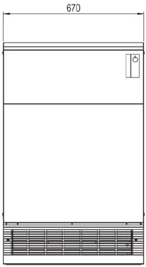
Fig. 1 Wall Mounting
2.3 Assembly and Electrical Connection
The heater should be only removed from its packaging near to its place of final assembly. Small cracks or chips in the heater core bricks have no influence on the operation of the heater.
2.3.1 Heater Assembly
-
Opening the heater (Fig. 2):
-
Prise off the plastic caps and remove the screws.
- Pull the side panels at the front outwards and remove them backwards.
- Lift the top panel (A) approx. 10mm .
- Pull the top panel forwards.
- Lift off the top panel.
- Pull the rear top panel (B) forwards.
- Lift off the rear top panel.
Remove the insulation, packaging and assembly material in the top of the heaters.
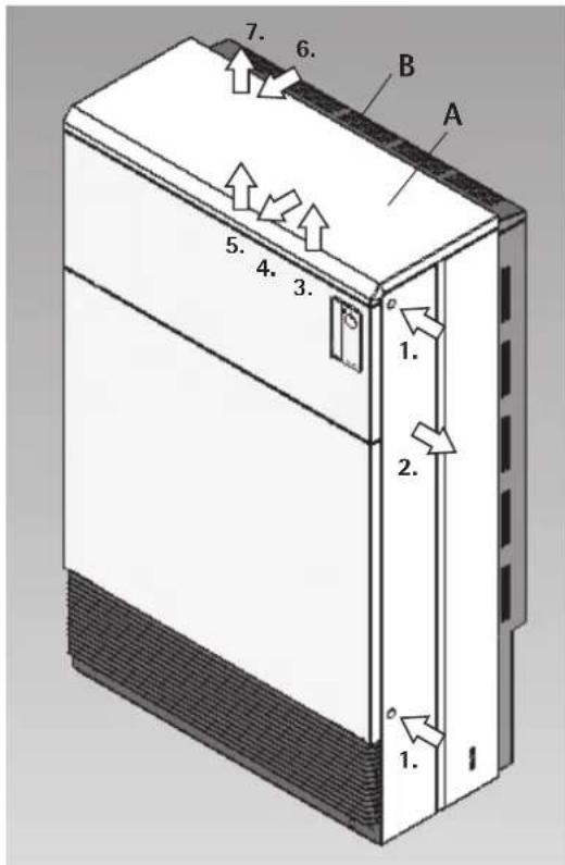
Fig. 2 Opening the heater
- Place the heater in its final position.
Align the fixing screw in its final position on the right or left hand inner panel and fix it firmly to the wall.
The wall fastening must be fixed to the heater with a self-tapping screw (permanent connection).
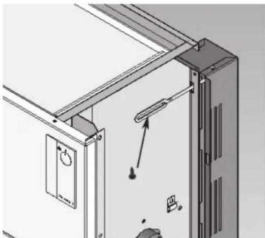
Fig. 3 Wall-fixing screw
Remove the top front panel (Fig. 4):
Caution: Before removing the top front panel of heaters with integral room thermostats, first remove the cables from the rocker switch on the operating panel.
- Remove the top and the side left and right screws from the top front panel (C).
- Remove the top front panel with both top front insulations.
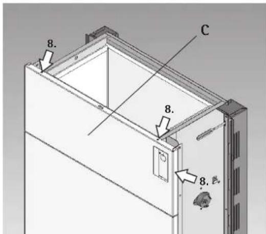
Fig. 4 Remove the top front panel
Insert the channelled bricks using the guide plates provided:
- Insert the channelled bricks SP27 (Fig. 5).
- Replace the top front panel with both top front insulations.
- Insert the channelled bricks from SP26.
You will find the number and type of storage brick packs in the section "Technical Data".
Note: Position the top row of the channeled bricks with the bevelled channeled guide facing upwards.
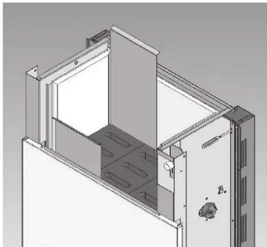
Fig. 5 Insert the channelled bricks SP27
- Insert the heating elements into the rows of slots in the storage core.
- Place the cover bricks on to the channel bricks over the heating elements in such a way that the terminals of the heating elements lie sidewards on the channels of the cover bricks. Remove the guide plates.
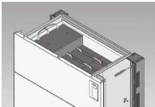
Fig. 6 Heating elements and cover bricks

- Pull the connection cords of the heating elements completely through the openings prepared and bow the connection cords at the coloured bushes carefully (Fig. 6).
Caution: Do not push the connection cords backwards to the interior.
- Fit the upper insulation mats tightly onto the cover bricks (Fig. 7).
Caution: Do not mix up upper insulation during installation!
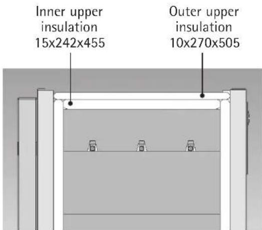
Fig. 7 Upper insulation
2.3.2 Element Ratings
You can choose from 3 different power ratings.
Connect the heating elements on to the terminal strip X2 depending on the power rating chosen according to the circuit diagram (page 28). The terminal strip is on the left hand side of the heater on the inside panel.
Cover up the non-applicable power ratings on the heater rating label (bottom right of heater) with the label provided (in the bag with the wall-fixing screw) - see example of rating label on page 29. For this, remove the protective paper from the adhesive side of the label. Position the adhesive side on the power rating to be covered by means of the frame-outline printed on the rating label. Press the covering label firmly and then remove the carrier foil. Proceed in the same way for the second rating to be covered.
Tip: It is easier to cover the rating if the edges of the label are cut off beforehand.
Put a cross against the chosen rating in the circuit diagrams, both in the Instruction Leaflet, and in the right hand inside panel.
- Connect the heating elements to the charge control according to circuit diagram (page 28).
Be careful that the capillary tubes do not touch live parts. - The heater is then re-assembled as described in Part 1-7 on page 24, but in reverse order.
2.3.3 Disassembly of Fan Diagram
For disassembly of drawer (e.g. for maintenance works) unscrew the air-outlet grille, release the inner screws (D) on the right and left side, turn them off about 15mm and press them back.
Remove right side panel.
Pull out the fan connection cable and the drawer.
When reassembling the drawer pull back the connection cable into the lateral control panel room and tighten the two screws (D) firmly. See that the drawer does not surpass the bottom plate of the heater at the front.
Refasten (finger-tight) right side panel and air outlet grill.
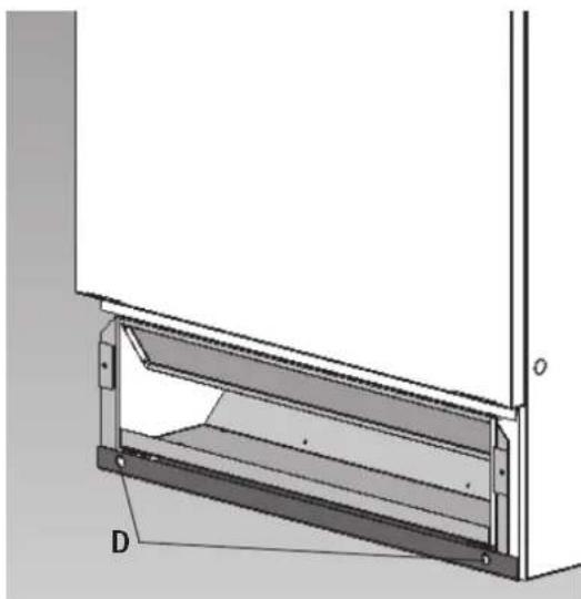
Fig. 8 Disassembly of fan drawer
2.3.4 Electrical Connection
The storage heater appliance is connected to a load current (OFF-PEAK tariff) and control cables for the room thermostat and for the charge control (A1/Z1; A2/Z2). The cables A1/Z1 and A2/Z2 are at line-voltage 230V and may thus be run together with a L/N/PE cable for the room thermostat. The heater is suitable for direct connection without a spur, or with a wall socket.

According to regulations every branch circuit must be individually protected, for instance by circuit breakers for all phases. These circuit breakers must have contact openings of at least 3mm .

Each heater must be connected to a separate current carrying cable from the electrical junction box. Running the load current cable from heater to heater is not allowed.

Since the technical connection conditions stipulated by the power supply companies permit a 1-phase connection of up to 2kW only, the appliance must always be connected to 3 phases.

When connecting to a charge control with a so-called "single-wire control", bridge the terminals "A2/Z2" and "N".

Make sure the earth wire is correctly and firmly attached.
2.3.5 Cable Feed
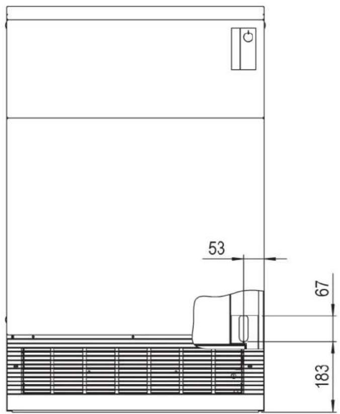
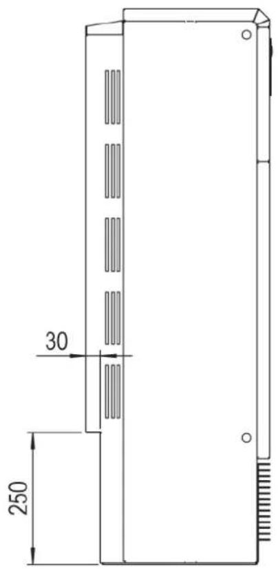
Fig. 9
2.3.6 Circuit Diagram WSP 600 HF
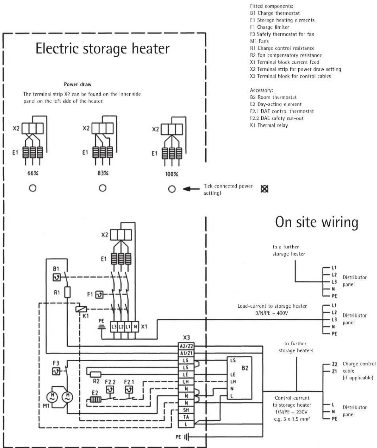
Caution! Even if the main circuit breakers are switched off, some terminals carrying on-peak current, especially terminals A1/Z1 and A2/Z2 can still be live.
Fig. 10
2.4 Rating Label
The specific technical data for each heater are printed on the rating label. You can find the rating label at the below the air-outlet grille on the right hand side of the heater.
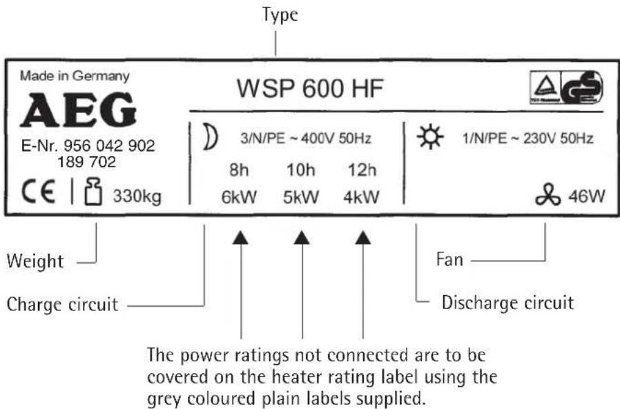
Fig. 11 Example of rating label for heater Type WSP 600 HF with power rating 6kW and nominal charge time of 8 hours
2.5 Spare Parts
In case any spare parts are needed for the heater, the type and fabrication number on the rating label must always be quoted.
You can find the fabrication number on the circuit diagram on the inside of the right hand side panel.
We recommend that you note the type and fabrication number as well as the charging time and connected power rating below during the installation:
Type number: WSP 600 HF
Fabrication number:
Nominal charge time: h
Connected power rating: kW
2.6 Accessories
2.6.1 Charge Control
The charge control registers the outside temperature and converts this value into a control current. This current is passed via the control wires A1/Z1 and A2/Z2 to the control resistance in each storage heater. At the same time, the temperature in the heater core is also registered. The switch-off point of the charge thermostat is therefore determined by both the outside temperature and the temperature of the heater core.
In this way, a control of charge according to the outside temperature and the residual heat in the heater is achieved, thus complying with Energy Saving Legislation.
The control wires can be run together with cable feeds L, N and PE.
Please also read the Instruction Leaflet supplied with the Charge Control.
2.6.2 Room Thermostat
The discharge of the storage heaters and thus the regulation of the room temperature is achieved using a room thermostat.
The type of thermostat and its configuration is dependent on the heater installation and the requirements of the user.
Please also read the Instruction Leaflet supplied with the Room Thermostat.
Integral Room Thermostat
The integral thermostat is designed for direct mounting to the heater itself:
- Thermo-mechanical room thermostat:
This type of thermostat switches the heater fan ON or OFF, according to the temperature required.
Electronic room thermostat:
The speed of the fan is regulated electronically according to the required room temperature.
External Room Thermostat
Following thermostats can be supplied:
- 2-point room thermostat
- 2-point room thermostat with thermal feedback
Electronic room thermostat
2.6.3 Thermal Switching Relay
By installing a thermal switching relay into each storage heater, the Utility relays in the junction box can be omitted.
Make certain that the installation of a thermal relay does not violate installation Codes of Practice of your local Utility.
Please also read the Instruction Leaflet supplied with the Thermal Switching Relay.
2.6.4 Day-acting Element
Using the day-acting element the heater can give off warmth immediately even if it is not charged at all. The day-acting element works on the ON-PEAK Tariff.
Switching and control of the Day-acting Element is to be carried out using an integral or external room thermostat suitable for this purpose.
Please also read the Instruction Leaflet supplied with the Day-acting Element.
2.6.5 Further Accessories
Further accessories such as Ceramic Tile Cladding etc. are available on demand. Contact your local dealer.
2.7 Commissioning the Heater
Following tests must be carried out before commissioning the heater:
Insulation test with a voltage of at least 500V . The dielectric resistance must be at least 0.5 MOhm.
Function Test
Check the function of the fan for the storage unit by switching on the room temperature regulator.
Charging
The units can be started without initial heating up after the function test. Charging takes place either manually with the adjuster of the mechanical charging control unit or automatically with the available Elfamatic charging control unit.
During initial charging, the charging in kWh must be determined and compared with the maximum permissible charging from the cold state specified in the "Technical Data". The determined charging may not exceed the maximum permissible charging from the cold state.

During initial charging, a smell may be produced, the room should therefore be adequately aired (1.5 times air change, e.g. tilted windows). Initial charging in the bedroom should not take place when sleeping in it if possible.
2.8 Re-assembly
Heaters that have already been in operation or have been taken apart and repositioned must be re-installed according to these instructions. The commissioning tests described on this page must also be carried out.
The first charging cycle after re-assembly must be monitored by the installer until the charge control switches off the elements.
Any insulation parts which are, or seem to be, damaged or have changed properties which could influence their function and safety, must be replaced.
3. Guarantee
For guarantee please refer to the respective terms and conditions of supply for your country.

The installation, electrical connection and first operation of this appliance should be carried out by a qualified installer.
The company does not accept liability for failure of any goods supplied which are not installed in accordance with the manufacturer's instructions.
3.1 Environment and recycling
Please help us to protect the environment by disposing of the packaging in accordance with the national regulations for waste processing.
2.2.4 Protection anti-basculement, fixation murale
2.3.4 Raccordement electrolyque


- Electric Storage Heaters
- WSP 600 HF
- François
- Contenu
- Operating Instructions
- Technical Description
- Operation
- Heat Storage
- Automatic Central Charge Control
- Manual Control
- Heat Discharge
- Summer Operation
- Energy saving tips
- Important Instructions
- Care and Maintenance
- Important note
- General
- This instruction leaflet must be:
- Defects
- Trouble Shooting Tips
- Heater does not store heat
- Heater always goes on full charge
- Heater does not give out enough heat
- Installation instructions
- Technical Data
- Heater Positioning and Installation
- Procedures to be followed
- Choosing the Heater Position
- Minimum Clearances
- Tilting Safety, Wall Mounting
- Heater Dimensions
- Assembly and Electrical Connection
- Heater Assembly
- Element Ratings
- Disassembly of Fan Diagram
- Electrical Connection
- Cable Feed
- Circuit Diagram WSP 600 HF
- Rating Label
- Spare Parts
- Accessories
- Charge Control
- Room Thermostat
- Integral Room Thermostat
- External Room Thermostat
- Thermal Switching Relay
- Day-acting Element
- Further Accessories
- Commissioning the Heater
- Re-assembly
- Guarantee
- Environment and recycling
- Protection anti-basculement, fixation murale
- Raccordement electrolyque
Brand : AEG
Model : WSP 600 HF
Category : Heating